Advertisement
Advertisement
Table of Contents

Related Manuals for Kicker KX150.2


Summary of Contents for Kicker KX150.2
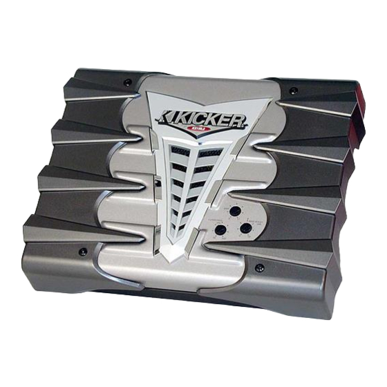
- Page 2 Amplifier Serial Number: KX150.2 / KX200.2 / KX250.2 You have just purchased the latest in amplifier technology to carry the famous KICKER name. Your KICKER KX series amplifier is designed and built to give you years of powerful and trouble-free performance. This installation...
- Page 3 EndKaps Cast aluminum, custom, removable covers to protect and hide all your wiring connections to the amplifier. Can be prepped and painted any custom color you choose. Two Year Warranty When purchased from an Authorized KICKER dealer. KX Amplifiers...
- Page 4 Mounting When selecting a location to mount your Kicker amplifier be sure it is structurally sound and that there are no items behind the area where the screws will be driven that could be damaged. Check for wire harnesses, brake lines, fuel lines, gas tanks, etc.
-
Page 5: Wiring
When working with power connections it is always recommended that you disconnect the battery to prevent accidents. Note: To get the best performance from your new Kicker Amplifier, we recommend using genuine Kicker Accessories and Wiring. The ground should be connected to the amplifier first before making any of the other connections. -
Page 6: System Diagrams
Speakers are rated at four ohms (some DC Resistances may be as low as 3 ohms) and work with any amplifier designed to oper- ate at a four ohm load. If you want to use two Kicker Coaxial or Component Speakers on a single channel of your amplifier wire the speakers in series. - Page 7 USING THE SIGNAL OUTPUT JACKS (PAST) The Output (Pre Amp Signal Transfer) RCA jacks allow you to send the incoming signal from one Kicker KX series amplifier to another amplifier or processor without the need for Y cables. The signal from the PAST jacks is identical to the signal fed to the amplifier via its RCA input jacks or the High Level inputs and is not affected by the amplifier’s built in crossover.
-
Page 8: Gain Control
Navigation On your Kicker amplifier there are three rotary controls on top and one switch on the end panel. These controls ensure the reliability and performance of the amplifier, so they need to be set correctly. CROSSOVER SWITCH NEVER CHANGE THE CROSSOVER “OFF/HI/LOW” SWITCH... -
Page 9: Troubleshooting
There are two LEDs on the end panel of your Kicker KX series amplifier, one green and one red. When the green LED is lit this indicates the amplifier is turned on and no trouble exists. If the green LED turns off and the red LED is lit, this indicates that the protection circuitry (SORT) is engaged. - Page 10 NOTE: All specifications and performance figures are subject to change. Please visit the support section at www.kicker.com for the most current information. Please Note: Modern high performance speakers have a lower DC Resistance than what used to be available.
-
Page 11: Specifications Common To All Models
12.75” 16” (32.38cm) (32.38cm) (40.64cm) KX Amplifiers Model KX150.2 60 x 2 @ 4 ohms, 14.4Vdc, 1% THD, CEA-2006 (Watts) Signal to Noise Ratio -102 CEA-2006 (ref: 1W, A-weighted) Model KX200.2 70 x 2 @ 4 ohms, 14.4Vdc, 1% THD,... -
Page 12: What Is Not Covered
ELECTRONICS LIMITED WARRANTY Kicker warrants this product to be free from defects in material and workmanship under normal use for a period of THREE (3) MONTHS from date of original purchase with receipt. When purchased from a Authorized KICKER Dealer it is warranted for TWO (2) YEARS from date of original purchase with receipt. - Page 13 Notes Tech Lines KX Amplifiers...
- Page 14 Hookups Pizza Delivery KX Amplifiers...
- Page 15 Chic’s Numbers KX Amplifiers...
Need help?
Do you have a question about the KX150.2 and is the answer not in the manual?
Questions and answers