Table of Contents
Advertisement
Quick Links
SECTION 1
SECTION 2
SECTION 3
SECTION 4
SECTION 5
SECTION 6
SECTION 7
SMART products are designed to deliver unsurpassed quality in workmanship and perfor-
mance. The following information gives detailed instructions on the installation and opera-
tion of the SMART MOD V processor. We strongly encourage new owners of the MOD V to
thoroughly read this entire manual before placing their new SMART product into service.
This will ensure that the MOD V will be operated properly to give the superior performance
that it was designed to deliver.
LIMITED WARRANTY: SMART products and accessories are warranted against malfunction or failure due to defects in workmanship or
materials for a period of one year from the date of shipment. If a problem occurs during the warranty period, the unit will be repaired, or
replaced at our option, without charge for materials or labor. If air freight is requested by the dealer, the difference between air and surface
charges will be billed to the dealer. This limited warranty does not cover products that have been abused, altered, modified, or operated in
other than specified conditions. Prior factory approval is required on all returns. Returned equipment or defective parts must be shipped
freight prepaid to us by the dealer or customer.
Our limited warranty does not cover damages resulting from accident, misuse or abuse, lack of responsible care, or failures not attributable to
manufacturing defects, except as provided herein. SMART Devices, Inc. makes no warranties, express or implied, including warranties of
merchantability or fitness for a particular purpose.
RETURN POLICY: Factory authorization MUST be obtained before returning any product. A 15% restocking charge will be issued on unused
equipment (in original box) that is returned for credit. Credit is issued to the dealers account. The credit may be used against future purchases
and no cash transactions are offered. All returns must be shipped freight prepaid by the dealer. Equipment returned without a factory RA
(Return Authorization) will be refused.
Table of Contents
INTRODUCTION ..............................................................2
CARD DESCRIPTION ......................................................3
INSTALLATION.................................................................7
-
CALIBRATION ..................................................................10
OPERATING INSTRUCTIONS.........................................13
SERVICE ..........................................................................13
SCHEMATICS ..................................................................16
For service or installation assistance, please call our
Technical Support Department between the hours of
8 a.m-5 p.m. E.S.T., Mon.-Fri.
1-800-45-SMART
Copyright 1995 by SMART Devices Inc.
5945 Peachtree Corners East
Norcross, GA 30071-1337
.................................7
.................................................10
.................................................12
Advertisement
Table of Contents

Related Manuals for SMART MOD V


Summary of Contents for SMART MOD V
-
Page 1: Table Of Contents
1-800-45-SMART LIMITED WARRANTY: SMART products and accessories are warranted against malfunction or failure due to defects in workmanship or materials for a period of one year from the date of shipment. If a problem occurs during the warranty period, the unit will be repaired, or replaced at our option, without charge for materials or labor. -
Page 2: Introduction
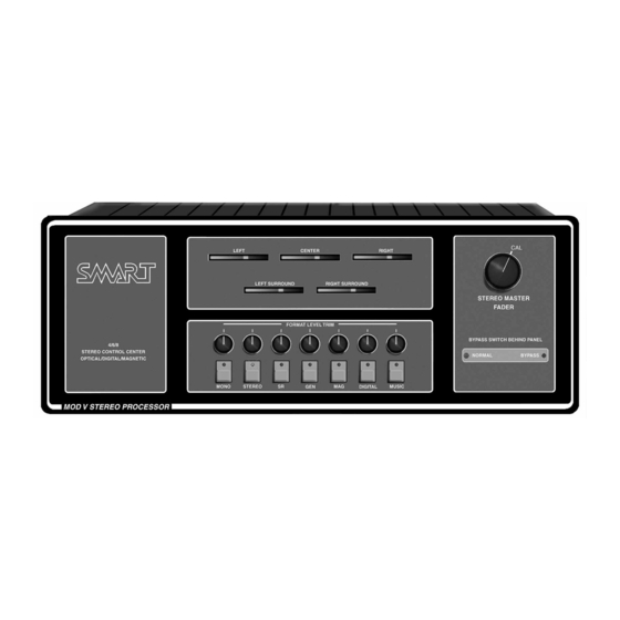
The operator control panel features a STATUS DISPLAY The SMART MOD V is fully equipped to handle your readout that shows the mode the system is in at any time. expansion needs. The MOD V will easily handle magnetic Red LED’s show which format is selected. -
Page 3: Card Description
NOISE REDUCTION CARDS: MD2BX374 The SMART noise reduction cards provide noise reduction for decoding Dolby type A stereo prints and Spectral Recording (SR) encoded prints. The noise reduction circuitry is automatically switched to the proper mode when selected by the format switches on the front of the processor. - Page 4 EXTERNAL INPUT/NR SWITCHING CARD: MOD5X349 This card handles several functions related to external mag- netic and digital signal sources, NR switching, and magnet- ic modes. Source selection of digital or magnetic signals is provided by electronic switching I.C’s. These determine which signals appear on the main signal busses of the MOD V.
- Page 5 INSTALLATION & OPERATION MATRIX CARD: MOD4X317 This is the heart of the stereo conversion process. The Wide Trac Deluxe Matrix card takes the signal from the preamp and noise reduction circuits and converts the two channel soundtrack into the four channels required for normal stereo mode.
- Page 6 OUTPUT/MUSIC CARD: MOD5X331 Eight channels of audio, comprised of the primary stereo channels (Left, Center, Right, Sub, Left Surround and Right Surround), along with the Left-Extra and Right-Extra chan- nels, pass through the MASTER VCA (Voltage Controlled Amplifiers). The digital inputs also allow for separate Left Surround and Right Surround channels in addition to a sep- arate subwoofer input.
-
Page 7: Installation
BYPASS GND. area that allows cool air to circulate around the individual components. In SMART prewired rack systems, the Power WIRING HOOKUP INSTRUCTIONS: Supply is mounted on the floor of the rack, and the rack-... - Page 8 DOUBLE CHECK your work to see that the solar cell leads projector TWO of the MOD V will be “enabled,” and the arrive at the proper terminals. A reversal of leads will cause first pair of stereo preamplifiers (PROJ 1) will be “dis- very strange results.
- Page 9 INSTALLATION & OPERATION the connection between the MOD V and a THX monitor. to access the back motherboard. Use extreme care when The cable should have a male DB25 on one end, and female removing and plugging in the circuit cards. Make sure on the other end.
-
Page 10: Calibration
B CHAIN CALIBRATION: PRELIMINARY: It is desirable to have a SMART PINK NOISE GENERA- TOR CARD and, optionally, an EXTENDER CARD for performing the calibration and testing of the MOD V. Note: Make sure the SMART Pink Noise Generator Card has the... - Page 11 INSTALLATION & OPERATION stage EQs can be used which gives an additional 6 dB of Now adjust the Left, Center and Right generator levels on gain. However, do not boost the gain on the EQ cards unless the Front Stereo Generator Card to read 82 dBC in the audi- it is absolutely necessary.
-
Page 12: A Chain Calibration
gain. Make sure that all other B-chain calibration adjust- ments have been made prior to adjusting the digital input levels on the External Input/NR Switching Card (see special note in the PRELIMINARY section of the B CHAIN CALI- BRATION). A CHAIN CALIBRATION: PRELIMINARY: 1. -
Page 13: Operating Instructions
INSTALLATION & OPERATION for left and both LED’s for right are on simultaneously. rium and on the booth monitor. MUSIC may also be select- There are preamp testpoints located just to the right of the ed by pressing the front panel Music button. calibration LED’s to which you may hook up an AC volt- meter to accurately measure the preamp levels. -
Page 14: Section 7 Schematics
(or similar piece of NEL(s). A signal at the input, through the filter circuit, the equipment) and have the unit fixed by SMART Devices or delay chip, and the anti-alias filter will reveal where the sig- another competent repair facility. - Page 15 REPLACEMENT PARTS: with the correct operation procedures. If you have difficulty finding parts for this or any other SMART product, The SMART Technical Support MANY IC DEVICES CAN BE DESTROYED BY HAN- Department stands ready to supply you with the required DLING.
Need help?
Do you have a question about the MOD V and is the answer not in the manual?
Questions and answers