Table of Contents
Advertisement
Quick Links
SECTION 1
SECTION 2
SECTION 3
SECTION 4
SECTION 5
SECTION 6
SECTION 7
SMART products are designed to deliver unsurpassed quality in workmanship and perfor-
mance. The following information gives detailed instructions on the installation and opera-
tion of the SMART MODIIB processor. We strongly encourage new owners of the MODIIB to
thoroughly read this entire manual before placing their new SMART product into service.
This will ensure that the MODIIB will be operated properly to give the superior performance
that it was designed to deliver.
LIMITED WARRANTY: SMART products and accessories are warranted against malfunction or failure due to defects in workmanship or
materials for a period of one year from the date of shipment. If a problem occurs during the warranty period, the unit will be repaired, or
replaced at our option, without charge for materials or labor. If air freight is requested by the dealer, the difference between air and surface
charges will be billed to the dealer. This limited warranty does not cover products that have been abused, altered, modified, or operated in
other than specified conditions. Prior factory approval is required on all returns. Returned equipment or defective parts must be shipped
freight prepaid to us by the dealer or customer.
Our limited warranty does not cover damages resulting from accident, misuse or abuse, lack of responsible care, or failures not attributable to
manufacturing defects, except as provided herein. SMART Devices, Inc. makes no warranties, express or implied, including warranties of
merchantability or fitness for a particular purpose.
RETURN POLICY: Factory authorization MUST be obtained before returning any product. A 15% restocking charge will be issued on unused
equipment (in original box) that is returned for credit. Credit is issued to the dealers account. The credit may be used against future purchases
and no cash transactions are offered. All returns must be shipped freight prepaid by the dealer. Equipment returned without a factory RA
(Return Authorization) will be refused.
Table of Contents
INTRODUCTION ..............................................................2
FEATURES.......................................................................2
CARD DESCRIPTION ......................................................3
INSTALLATION.................................................................8
-
CALIBRATION ..................................................................10
OPERATING INSTRUCTIONS.........................................14
SCHEMATICS ..................................................................15
For service or installation assistance, please call our
Technical Support Department between the hours of
8 a.m-5 p.m. E.S.T., Mon.-Fri.
1-800-45-SMART
Copyright 1995 by SMART Devices Inc.
5945 Peachtree Corners East
Norcross, GA 30071-1337
.................................8
.................................................10
.................................................12
Advertisement
Table of Contents

Related Manuals for SMART MOD IIB


Summary of Contents for SMART MOD IIB
-
Page 1: Table Of Contents
1-800-45-SMART LIMITED WARRANTY: SMART products and accessories are warranted against malfunction or failure due to defects in workmanship or materials for a period of one year from the date of shipment. If a problem occurs during the warranty period, the unit will be repaired, or replaced at our option, without charge for materials or labor. -
Page 2: Introduction
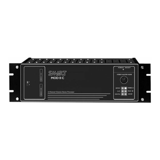
Installation and Service Manual MODIIB Digital/Optical Cinema Processor SECTION 1: control is located behind the front panel on the Format Card. INTRODUCTION FORMAT SWITCHING: The MODIIB Cinema Stereo Processor is a full four The formats available on the MODIIB are Mono, 3-D channel system featuring the latest technology in opti- Mono, Stereo A, Film SR, Digital and Music. -
Page 3: Card Description
INSTALLATION & OPERATION SURROUND CHANNEL TIME DELAY: The MODIIB has a digital time delay circuit for the surround channel while playing optical stereo prints. Time delay of the surround channel in optical stereo mode is necessary for two reasons: 1) to mask any front to sur- round crosstalk and, 2) to synchronize the stage and surround channels to eliminate echo caused by different sound path lengths from the stage and surround speakers. -
Page 4: Dual Projector Preamp Card: Mod4X300
MODIIB STEREO PROCES- TIONS section). Jumper H2 is used to select whether or not the 3-D feature is on or off for Mono mode when the processor is powered on (see diagram). Units are shipped to power up with the 3-D function active. -
Page 5: Meter Card: Mod2X335
NOISE REDUCTION CARDS: MD2Bx374 The SMART noise reduction cards provide noise reduction for decoding Dolby type A stereo prints and Spectral Recording (SR) encoded prints. The noise reduction circuitry is automatically switched to the proper mode when selected by the format switches on the front of the processor. There are four trimpots and two test points on each... -
Page 6: Matrix Card: Mod4X317
MODIIB STEREO PROCESSOR MATRIX CARD: MOD4x317 This is the heart of the stereo conversion process. The Wide Trac Deluxe Matrix card takes the signal from the preamp and noise reduction circuits and converts the two channel soundtrack into the four channels required for normal stereo mode. -
Page 7: Installation
In SMART prewired rack systems, the Power Supply is mounted on the floor of the rack, and the rack-mounted processor is placed at eye level for easy visibility of the system operation status. -
Page 8: Wiring Hookup Instructions
MODIIB STEREO PROCESSOR strip that screws onto the back of the MODIIB. Make error, so verify correct wiring before proceeding. sure to observe polarity. As you are looking at the back of the MODIIB, the top left terminal strip is CHANGEOVER WIRING OF DUAL PROJECTOR where the power supply harness attaches. - Page 9 Make sure power is removed from the system INPUTS on the back of the processor is for an external before removing any card or plugging one in. digital decoder. SMART provides the proper cables for the different digital decoders available on the mar- OUTPUTS: ket.
-
Page 10: Calibration
Monitor the preamp signals with the oscilloscope. For more detailed information about setting up Adjust for minimum signal on the left and right chan- SMART processors, see the Theatre Sound for SMART nels. Refer to specific instructions in the projector Systems guide. - Page 11 INSTALLATION & OPERATION Make sure the response is the same on both channels. With a narrow slit optical lens, the response should be flat within ± 3 dB to about Diagram 1 12 kHz with NO slit loss correction. If not, this MUST be corrected before proceeding with the next steps.
-
Page 12: B Chain Calibration
Before continuing with the B Chain calibration, check the wiring of all auditorium speak- ers to make sure the phase is correct. The “SMART EZ Phase Checker” is a perfect unit for verifying proper phase of speakers. - Page 13 INSTALLATION & OPERATION position. ISO Cinema playback standard states that 1/3 octave bands should be tuned for flat response to 2 kHz, with a 3 EQUALIZATION AND HOUSE LEVELS: dB/octave rolloff above 2K. Diagram 3 The equalizers are normally shipped with the individual trimpots set for a flat frequency response.
-
Page 14: Operating Instructions
MODIIB STEREO PROCESSOR OPERATING thirds up from its counterclockwise position . Select Music mode and turn on the music source that is feed- INSTRUCTIONS ing the MODIIB. Turn the left and right music level trimpots on the Output/Music Card to obtain a nor- mal house level. -
Page 15: Schematics
INSTALLATION & OPERATION This trimpot is located on the lower right side of the page 23-24 Format Card. The four screws holding the front panel of the MODIIB must be removed to access the MUSIC One Octave EQ Card (MOD4x324) – page 25 LEVEL control.
Need help?
Do you have a question about the MOD IIB and is the answer not in the manual?
Questions and answers