Table of Contents
Advertisement
Quick Links
Devices, Inc.
Eight-channel stereo processor
Digital EX format included
Easy interface to digital
soundtrack players
Simple operation
2 Rack Spaces
UL Listed, universal voltage
power supply
A/V input for VCR, DVD, or
LaserDisc
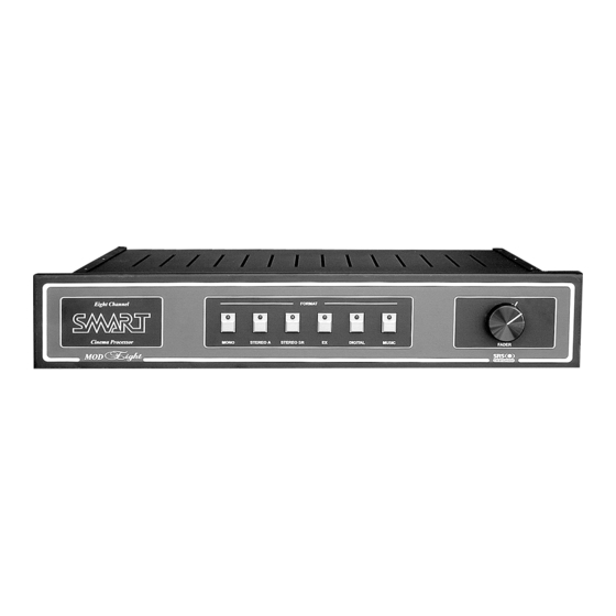
MOD 8
Eight Channel Cinema Stereo Processor
With Circle Surround Analog Matrix
I
NSTALLATION AND
O
PERATION
Copyright 2004 by SMART Devices, Inc.
5945 Peachtree Corners East
Norcross, GA 30071-1337
Publication Number MOD8A600.p65
M
ANUAL
1-800-457-6278
or
770-449-6698
10042004
Advertisement
Table of Contents

Related Manuals for SMART MOD 8


Summary of Contents for SMART MOD 8
- Page 1 NSTALLATION AND Simple operation PERATION ANUAL 2 Rack Spaces UL Listed, universal voltage power supply A/V input for VCR, DVD, or LaserDisc Copyright 2004 by SMART Devices, Inc. 5945 Peachtree Corners East Norcross, GA 30071-1337 1-800-457-6278 770-449-6698 Publication Number MOD8A600.p65 10042004...
-
Page 2: Support
Please consult with your Dealer, Installer, Technician or the SMART factory for any unusual situations involving the connection and use of this product with equipment from other manufacturers. When properly connected and operated, this product should deliver outstanding results. -
Page 3: Table Of Contents
INSTALLATION & OPERATION Table of Contents SUPPORT ---------------------------------------------------------------------------------------------------------------------------------------------------------------------------- 2 LIMITED WARRANTY ---------------------------------------------------------------------------------------------------------------------------------------------------------- 2 RETURN POLICY ------------------------------------------------------------------------------------------------------------------------------------------------------------------ 2 INTRODUCTION ----------------------------------------------------------------------------------------------------------------------------------------------------------------- 4 FEATURES --------------------------------------------------------------------------------------------------------------------------------------------------------------------------- 5 Circle Surround DSP Matrix --------------------------------------------------------------------------------------------------------------------------------------------- 5 Fader Control/Remote Equalization Settings ----------------------------------------------------------------------------------------------------------------------- 5 Format Switching ------------------------------------------------------------------------------------------------------------------------------------------------------------ 5 Solar Cell/Reverse Scan Inputs ----------------------------------------------------------------------------------------------------------------------------------------- 5 Digital Inputs ----------------------------------------------------------------------------------------------------------------------------------------------------------------- 5 Music Inputs ------------------------------------------------------------------------------------------------------------------------------------------------------------------ 5 Surround Channel Time Delay ----------------------------------------------------------------------------------------------------------------------------------------- 5... -
Page 4: Introduction
MOD 8 STEREO PROCESSOR INTRODUCTION The MOD 8 Cinema Stereo Processor is an inexpensive, full-featured product which allows any theatre to provide the best presentation to its customers. Whether as an upgrade or in new installations, the MOD 8 offers features, ease of use, and pricing that are sure to please anyone. -
Page 5: Features
DVD, LaserDisc, or VCR players. optical sound presentations in auditoriums that are The music inputs are processed through the Circle equipped for split surround operation. SMART is the Surround matrix. first manufacturer to introduce this technology into professional cinema applications. -
Page 6: Configuration
MOD 8 STEREO PROCESSOR CONFIGURATION The MOD 8 has a number of configuration options which are detailed in the following sections. Most of the configuration options are selected throught the use of shunts (or jumpers) placed on header pins. Some of the options (such as those on the matrix board) are selected through the use of DIP switches. -
Page 7: Overhead Channel Configuration
INSTALLATION & OPERATION Overhead Channel Configuration The MOD 8 can be configured to deliver an overhead channel from digital soundtracks. If you are using a digital player and have installed overhead speakers and amplifiers, then place this shunt in the OS position. Otherwise, leave it in the CS position. -
Page 8: Matrix Configuration
MOD 8 STEREO PROCESSOR MATRIX CONFIGURATION The CONFIGURATION DIP switches are used for setting SW1-6 selects Front/Surround Mode or Multi-channel the various operating modes. The PINK NOISE DIP Mode. switches are used for selecting which channels receive the pink noise signal for level setting and equalization. SW1-7 causes the matrix to always be in Cinema mode. -
Page 9: Time Delay Setup
INSTALLATION & OPERATION PINK NOISE SWITCH FUNCTIONS CONFIGURATION SWITCH FUNCTIONS ON - PINK NOISE OFF - NORMAL Left Channel Force Music Mode Auto Cinema/Music Mode Center Channel Mono Surrounds Split Surrounds Right Channel Soundspread On Soundspread Off Left Wall Surround Channel Phantom Center Real Center Right Wall Surround Channel... -
Page 10: Installation
MOD 8 STEREO PROCESSOR INSTALLATION Processor Placement Before mounting the MOD 8 processor in the equipment rack or projector console, be sure to select a well ventilated area that allows cool air to circulate around the individual components. Make sure that the processor is not immediately adjacent to hum producing components such as power amplifiers with large transformers. -
Page 11: Two Projector Systems
Connecting the MOD 8 to a Reverse Scan soundhead. SMART recommends using a stereo distribution amplifier Two Projector Systems such as the SMART DA226 to feed signals from one music Connect the CHANGEOVER and GROUND terminals on source to multiple sound processors. -
Page 12: Digital Player Connections
Right Wall channels. Pin 19 Left Wall Pin 21 Right SMART has interconnection cables available to connect the Pin 23 Center popular digital player systems to the MOD 8. Simply plug Pin 25 Left the appropriate DB25 connector to the MOD 8 DIGITAL... -
Page 13: System Setup
INSTALLATION & OPERATION SYSTEM SETUP Required Equipment Turn the master FADER all the way down to avoid excessive noises in the auditorium for the next steps. · sound pressure level meter · real time analyzer (RTA) with a calibrated microphone Soundhead Alignment ·... -
Page 14: Slit Loss Correction
MOD 8 STEREO PROCESSOR 10 Observe the real time analyzer and focus the lens for 2. Adjust the left and right slit loss correction trimpots on maximum high frequency output while maintaining the the PREAMP for optimum flat high frequency response. best azimuth. -
Page 15: Bypass Setup
INSTALLATION & OPERATION You can verify that the LED meters are indicating correctly by connecting an AC voltmeter to the LEFT PRE (TP7) and RIGHT PRE (TP8) test points located on the bottom side of the front of the main circuit board between connectors J1 and J2. -
Page 16: Subwoofer Levels
MOD 8 STEREO PROCESSOR The music is played through the matrix the same as a soundtrack and provides 6 channel decoding from a conventional 2-channel stereo source. This feature in the MOD 8 presents a high impact playback in the auditorium for pre-show entertainment. - Page 17 INSTALLATION & OPERATION Bypass Switch Left EQ Center EQ Left Wall EQ Right Wall EQ A-Chain trimpots Rear EQ Right EQ B-Chain trimpots Fader Pot Front Panel Interior View The Hearing Impaired level and Backup Level adjustments are located in the A-Chain trimpots section on the left hand end of the main board.
-
Page 18: Operating Instructions
If this happens, please contact sequence, it is recommended that the amplifiers be turned your service technician or call the SMART factory. off before the processor to avoid a “turn-off thump” in the auditorium.
Need help?
Do you have a question about the MOD 8 and is the answer not in the manual?
Questions and answers