Table of Contents
Advertisement
Advertisement
Table of Contents

Subscribe to Our Youtube Channel
Related Manuals for Zotac H55-ITX wifi series


Summary of Contents for Zotac H55-ITX wifi series
-
Page 2: Electronic Emission Notices
Electronic Emission Notices WARNING! Federal Communications Commission (FCC) Statement This equipment has been tested and found to comply with the limits for a Class B digital device, pursuant to Part 15 of FCC Rules. These limits are designed to provide reasonable protection against harmful interference in a residential installation. -
Page 3: Table Of Contents
Intel H55-ITX series Motherboard Table of Contents Motherboard Specifications ---------------------------------------------------------------------------------4 Motherboard Layout--------------------------------------------------------------------------------------------6 Hardware Installation ------------------------------------------------------------------------------------------9 Safety Instructions -------------------------------------------------------------------------------------------9 Preparing the Motherboard ----------------------------------------------------------------------------------10 Installing the CPU -------------------------------------------------------------------------------------------10 Installing the CPU Fan -------------------------------------------------------------------------------------11 Installing Memory DIMMs ---------------------------------------------------------------------------------11 Installing the Motherboard ---------------------------------------------------------------------------------12 Installing the I/O Shield ------------------------------------------------------------------------------------12 Securing the Motherboard into the Chassis ----------------------------------------------------------12 Connecting Cables and Setting Switches --------------------------------------------------------------13 24-pin ATX Power Connector-PW1 ---------------------------------------------------------------------14... - Page 4 Table of Contents Smbios Configuration ---------------------------------------------------------------------------------22 Trusted Computing ------------------------------------------------------------------------------------22 USB Configuration -------------------------------------------------------------------------------------22 PCI/PnP Menu -----------------------------------------------------------------------------------------------23 Boot Menu -----------------------------------------------------------------------------------------------------24 Security Menu ------------------------------------------------------------------------------------------------25 Chipset Menu -------------------------------------------------------------------------------------------------26 Exit Menu ------------------------------------------------------------------------------------------------------26 Flash Update Procedure ----------------------------------------------------------------------------------27 Installing Drivers and Software --------------------------------------------------------------------------------28 Driver Installation -------------------------------------------------------------------------------------------------28 Realtek HD Audio Driver Setup ------------------------------------------------------------------------------39 Getting Started -----------------------------------------------------------------------------------------------39 Sound Effect --------------------------------------------------------------------------------------------------39 Environment Simulation ------------------------------------------------------------------------------39...
-
Page 5: Motherboard Specifications
Intel H55-ITX series Motherboard Motherboard Specifications q Chipset v Intel ® H55 Express Chipset q Size v MINI ITX form factor of 6.7 X 6.7 inch q Microprocessor support v Supports LGA 1156 socket for Intel ® Core i3/Core i5 processors q Operating systems v Supports Windows XP 32bit/64bit, Windows Vista 32bit/64bit and Windows 7 32bit/64bit q System Memory... -
Page 6: Expansion Slots
Motherboard Specifications q Audio v 7.1+2 channel High Definition Audio Codec v All DACs support 192k/96k/48k/44.1kHz sample rate v One SPDIF-out header on board q Green Function v Support SMM, APM, ACPI v Suspend to DRAM supported (STR) v RTC timer to power-on the system v AC power failure recovery q Onboard Graphics Features v DX10 and OpenGL 2.0 are supported... -
Page 7: Motherboard Layout
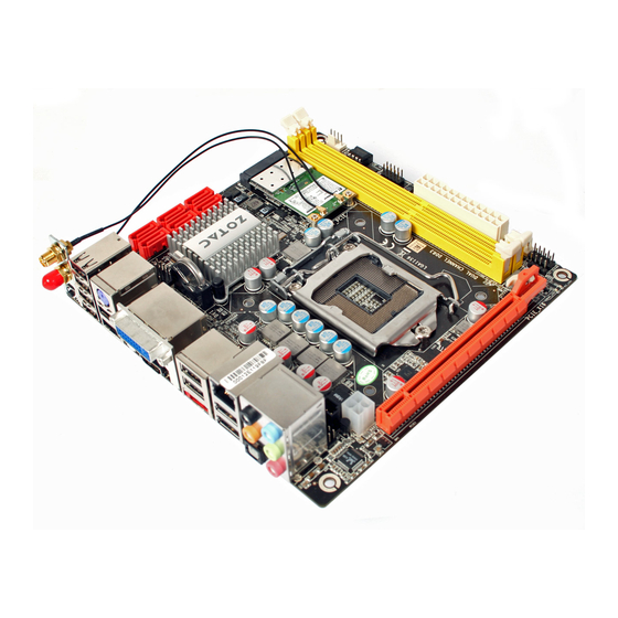
Intel H55-ITX series Motherboard Motherboard Layout Figure 1 shows the motherboard and Figure 2 shows the back panel connectors. MINI_PCIE1 SATA1 SATA3 SATA5 SATA2 SATA4 SATA6 Chipset 115XLM REMOVE FP_S1 PCIE1 Figure 1 Figure 1. Board Layout 1. SYS Fan Connector-SYSFAN1 10. - Page 8 Rear panel Figure 2. Backpanel connectors 1. Clear CMOS Button 2. USB Ports (Optional) 3. HDMI Port 4. eSATA Port 5. USB Ports 6. Optical SPDIF Output 7. Port 2-Channel 4-Channel 6-Channel 8-Channel Blue Line-In Line-In Line-In Side Speaker Out Green Line-Out Front Speaker Out...
- Page 9 Intel H55-ITX series Motherboard Step 2. Secure the bracket to the motherboard with screws according to the picture below. Bracket Screws Step 3. Connect the WiFi wires to the MINI PCIE card as the following picture shows. WiFi wires MINI PCIE card 115XLM Bracket...
-
Page 10: Hardware Installation
Hardware Installation Hardware Installation This section will guide you through the installation of the motherboard. The topics covered in this section are: q Preparing the motherboard v Installing the CPU v Installing the CPU fan v Installing Memory DIMMs q Installing the motherboard q Connecting cables and setting switches Safety Instructions To reduce the risk of fire, electric shock, and injury, always follow basic safety precautions. -
Page 11: Preparing The Motherboard
Intel H55-ITX series Motherboard Preparing the Motherboard The motherboard shipped in the box does not contain a CPU or memory DIMM. You need to purchase them to complete this installation. Installing the CPU Be very careful when handling the CPU. Make sure not to bend or break any pins on the back. Hold the processor only by the edges and do not touch the bottom of the processor. -
Page 12: Installing The Cpu Fan
Hardware Installation Installing the CPU Fan There are many different fan types that can be used with this motherboard. Follow the instruction that came with your fan assembly. Be sure that the fan orientation is correct for your chassis type and your fan assembly. -
Page 13: Installing The Motherboard
Intel H55-ITX series Motherboard Installing the Motherboard The sequence of installing the motherboard into the chassis depends on the chassis you are using and if you are replacing an existing motherboard or working with an empty chassis. Deter- mine if it would be easier to make all the connections prior to this step or to secure the mother- board and then make all the connections. -
Page 14: Connecting Cables And Setting Switches
Hardware Installation Connecting Cables and Setting Switches This section takes you through all the connectors and switch settings necessary on the mother- board. This will include: q Power Connectors v 24-pin ATX Power Connector-PW1 v 4-pin ATX_12V Power Connector-PW2 q Internal Headers/Connectors v SPDIF-Out Header-CN5 v COM Header-CN4 (Optional) v Front Panel Header-FP1... -
Page 15: 24-Pin Atx Power Connector-Pw1
Intel H55-ITX series Motherboard 24-pin ATX Power Connector-PW1 PW1 is the main power supply connector. Make sure that the power supply cable and pins are properly aligned with the connector on the motherboard. Firmly plug the power supply cable into the connector and make sure it is secure. -
Page 16: Spdif-Out Header-Cn5
Hardware Installation SPDIF-Out Header-CN5 This header provides a SPDIF (Sony/Philips Digital Interface) output to digital multimedia device through coaxial connector. CN5 - Pin Definition COM Header-CN4 (Optional) Signal CN4 - Pin Definition Signal Signal SPDIF-out Front panel header-FP1 The front panel header on this motherboard is one connector used to connect the following four cables : 115XLM... -
Page 17: Usb Headers-Fp_U1~Fp_U2
Intel H55-ITX series Motherboard USB Headers-FP_U1~FP_U2 This motherboard contains ten optional USB 2.0 ports that are exposed on the rear panel of the chassis. The motherboard also contains two 10-pin internal headers connector onboard. Note: Secure the bracket to either the front or rear panel of your chassis (not all chassis are equipped with the front panel option). -
Page 18: Speaker Header-Spk1
Hardware Installation Speaker Header-SPK1 SATA1 SATA3 SATA5 SPK1-Pin Definition Assignment SATA2 SATA4 SATA6 +12V SPK- Sense Control SYSFAN1 115XLM Control Sense REMOVE +12V CPUFAN1 SPK1 SATA-Pin Definition Serial-ATA (SATA) Connectors (SATA1~6) Signal The Serial ATA connector is used to connect the Serial ATA device to the motherboard. -
Page 19: Expansion Slots
Intel H55-ITX series Motherboard Expansion Slots The motherboard contains two expansion slots, one Mini PCIE slot and one PCIE x16 slot. MINI_PCIE1 115XLM REMOVE PCIE1 Mini PCIE Slot-MINI_PCIE1 There is one Mini PCIE slot, reserved for the WiFi Module. PCIE x16 Slot-PCIE1 There is one PCIE x16 slot reserved for graphics card. -
Page 20: Configuring The Bios
Configuring the BIOS Configuring the BIOS This section discusses how to change the system settings through the BIOS Setup menus. Detailed descriptions of the BIOS parameters are also provided. Enter BIOS Setup The BIOS is the communication bridge between hardware and software. Correctly setting the BIOS parameters is critical to maintain optimal system performance. -
Page 21: Advanced Menu
Intel H55-ITX series Motherboard Advanced Menu The Advanced menu items allow you to change the setting for the CPU and other system devices. Press <enter> to display the configuration options: CPU Configuration The items in this menu show the CPU-related information that the BIOS automatically detects. -
Page 22: Ide Configuration
Configuring the BIOS q Intel(R) HT Technology This item allows you to enable or disable Intel ® Hyper-Threading technology support . q Active Processor Cores This item allows you to choose the number of the active processor cores. The default value is [All]. q A20M This item allows you to enable or disable A20M. -
Page 23: Pci Express Configuration
Intel H55-ITX series Motherboard PCI Express Configuration The item in this menu allows you to enable or disable PCI Express L0s and L1 link power states. Smbios Configuration The item in this menu allows you to enable or disable Smbios Smi Support. Trusted Computing The item in this menu allows you to enable or disable TCG/TPM support in BIOS. -
Page 24: Pci/Pnp Menu
Configuring the BIOS PCI/PnP Menu The PCI PnP menu items allow you to change the advanced settings for PCI/PnP devices. The menu includes setting IRQ and DMA channel resources for either PCI/ PnP or legacy ISA devices, and setting the memory size block for legacy ISA devices. Press <enter>... -
Page 25: Boot Menu
Intel H55-ITX series Motherboard q Palette Snooping When set to [Enabled], the pallete snooping feature informs the PCI devices that an ISA graphics device is installed in the system so that the latter can function correctly. q PCI IDE BusMaster When set to [Enabled], BIOS use PCI busmastering for reading/writing to IDE drives. -
Page 26: Security Menu
Configuring the BIOS q PS/2 Mouse Support Allows you to enable or disable support for PS/2 mouse. q Wait for ‘F1’ If Error When set to [Enabled], the system waits for the F1 key to be pressed when error occurs. q Hit ‘DEL’... -
Page 27: Chipset Menu
Intel H55-ITX series Motherboard Chipset Menu The chipset menu items allow you to change the advanced chipset settings. Press <enter> to display the sub-menu: North bridge Configuration The item allows you to configure north bridge features, including Memory, Graphic, NB PCIE and so on. South bridge Configuration The item allows you to configure south bridge features, including USB, HDA, SMBUS, and so on. -
Page 28: Flash Update Procedure
Configuring the BIOS Save Changes and Exit Select this item and press <Enter> to save the changes that you have made in the BIOS Setup and exit the BIOS Setup. When the diolog box [Save configuration changes and exit setup?] appears, select [Ok] to save and exit, or select [Cancel] to return to the main menu. -
Page 29: Installing Drivers And Software
Intel H55-ITX series Motherboard Installing Drivers and Software Note: It is important to remember that before installing the driver CD that is shipped in the kit, you need to load your operating system. The motherboard supports Windows XP 32 bit/64 bit, Windows Vista 32 bit/64 bit and Windows 7 32bit/64bit. The kit comes with a CD that contains utility drivers and additional INTEL software. - Page 30 Installing Drivers And Software Note. If the MINI PCIE card is installed, the option Atheros Wireless driver will display as the following window. 2. Left-click Intel chipset Driver, begin loading...
- Page 31 Intel H55-ITX series Motherboard 3. Left-click HDA sound driver, begin loading...
- Page 32 Installing Drivers And Software 4. Left-click Intel Graphics Driver, begin loading...
- Page 33 Intel H55-ITX series Motherboard...
- Page 34 Installing Drivers And Software 5. Left-click JMB36X driver, begin loading...
- Page 35 Intel H55-ITX series Motherboard 6. Left-click Intel(R) PRO Network Driver, the following notepad will guide you to install Intel ® PRO network driver:...
- Page 36 Installing Drivers And Software Follow the steps below to install Intel(R) PRO Network Driver.
- Page 37 Intel H55-ITX series Motherboard...
- Page 38 Installing Drivers And Software 7. Left-click Atheros Wireless driver, begin loading...
- Page 39 Intel H55-ITX series Motherboard At last, you can enter Computer Management that provides information about the hardware devices on this motherboard to check if the driver installation is complete.
-
Page 40: Realtek Hd Audio Driver Setup
Installing Drivers And Software Realtek HD Audio Driver Setup Getting Started After Realtek HD Audio Driver being installed (insert the driverCD and follow the on-screen instruc- tions), “Realtek HD Audio Manager” icon will show in System tray as below. Double click the icon and the control panel will appear: Sound Effect After clicking on the “Sound Effect”... -
Page 41: Equalizer Selection
Intel H55-ITX series Motherboard Equalizer Selection The Equalizer section allows you to create your own preferred settings by utilizing this tool. In standard 10 bands of equalizer, ranging from 100Hz to 16KHz are available: Frequently Used Equalizer Setting Realtek recognizes the needs that you might have. By leveraging our long experience at audio field, Realtek HD Audio Sound Manager provides you certain optimized equalizer settings that are frequently used for your quick enjoyment. -
Page 42: Mixer
Installing Drivers And Software Mixer Realtek HD Audio Sound Manager integrates Microsoft’s “Volume Control” functions into the Mixer page. This gives you the advantage to you to create your favorite sound effect in one single tool. Playback control Mute You may choose to mute single or multiple volume controls or to completely mute sound output. Tool √... -
Page 43: Recording Control
Intel H55-ITX series Motherboard With this function, you will be able to have an audio chat with your friends via headphone (stream 1 from front panel) while still have music (stream 2 from back panel) playing. At any given period, you can have maximum 2 streams operating simultaneously. Recording control Mute You may choose to mute single or multiple volume controls or to completely mute sound input. -
Page 44: Audio I
Installing Drivers And Software Audio I/O Realtek HD Audio Manager frees you from default speaker settings. Different from before, for each jack, they are not limited to perform certain functions. Instead, now each jack is able to be chosen to perform either output (i.e. playback) function or input (i.e. Recording) function, we call this “Retasking”. -
Page 45: Speaker Configuration
Intel H55-ITX series Motherboard Speaker Configuration Step 1: Plug in the device in any available jack. Step 2: Dialogue “connected device” will pop up for your selection. Please select the device you are trying to plug in. * If the device is being plugged into the correct jack, you will be able to find the icon beside the jack changed to the one that is same as your device. -
Page 46: Connector Settings
Installing Drivers And Software Connector Settings Click to access connector settings √ Mute rear panel when front headphone plugged in Once this option is checked, when front headphone is plugged, the music that is playing from the back panel, will be stopped. √... -
Page 47: Speaker Calibration
Intel H55-ITX series Motherboard √ Output Sampling Rate 44.1KHz: This is recommended while playing CD 48KHz: This is recommended while playing DVD or Dolby. 96KHz: This is recommended while playing DVD-Audio. √ Output Source Output digital audio source: The digital audio format (such as .wav, .mp3, .midi etc) will come out through S/PDIF-Out. -
Page 48: Microphone
Installing Drivers And Software Microphone This page is designed to provide you better microphone/recording quality. Below picture indicates both “Noise Suppression” & “Acoustic Echo Cancellation” are both enabled. Noise Suppression If you feel that the background noise, especially the sound generated from the fan inside PC, is too loud? Try “Noise Suppression”, which allows you to cut off and suppress disturbing noise. -
Page 49: Audio Demo
Intel H55-ITX series Motherboard Audio Demo The section “3D Audio Demo” grants you another possibility to enjoy your sound. The Audio Demo allows you to listen to sound in an extraordinary way. Information This section provides information about your current system audio device. 291-MA130-02...
Need help?
Do you have a question about the H55-ITX wifi series and is the answer not in the manual?
Questions and answers