Advertisement
Owner's Manual
rRnFTSMRNo
5.5 HP
24 INCH TINE WIDTH
FRONT TINE TILLER
Model No.
917.292390
• Safety
• Assembly
• Operation
• Maintenance
• Espa_ol
• Repair Parts
CAUTION:
Read and follow all
Safety Rules and Instructions
before operating this equipment
Sears, Roebuck and Co., Hoffman Estates, IL 60179
Visit our Craftsman
website:www.sears,
com/craftsman
Advertisement
Table of Contents

Related Manuals for Craftsman 917.292390


Summary of Contents for Craftsman 917.292390
- Page 1 917.292390 • Safety • Assembly • Operation • Maintenance • Espa_ol • Repair Parts CAUTION: Read and follow all Safety Rules and Instructions before operating this equipment Sears, Roebuck and Co., Hoffman Estates, IL 60179 Visit our Craftsman website:www.sears, com/craftsman...
- Page 2 Warranty applies for only thirty (30) days from the date of purchase. Warranty service is available by returning the Craftsman Tiller to the nearest Sears ser- vice center/department in the United States. This warranty applies only while this prod- uct is in use in the United States.
-
Page 3: Operation
MAINTENANCE STORAGE OPERATION • Keep machine, attachments, • Do not put hands or feet near or under accessories in safe working condition. rotating pads. • Check shear p_ns, engine mounting • Exercise extreme caution when operat- bolts, and other bolts at frequent inter- ing on or crossing gravel drives, walks, or roads. - Page 4 MAINTENANCE AGREEMENT PRODUCT SPECIRCAllONS A Sears Maintenance Agreement is avail- HORSEPOWER: 5.5 HP able on this product. Contact your nearest )ISPLACEMENT: 13 CU. IN. Sears store for details. (221CC) CUSTOMER RESPONSIBILITIES ;ASOLINE CAPACITY: 4 Quads • Read and observe the safety rules. Unleaded Regular •...
- Page 5 Your new tiller has been assembled at the FFont factory with exception of those parts left unassembled for shipping purposes. ensure safe and proper operation of your tillre all parts and hardware you assemble must be tightened securely. Use the correct tools as necessary to insure proper tight- Bess.
-
Page 6: Handle Height
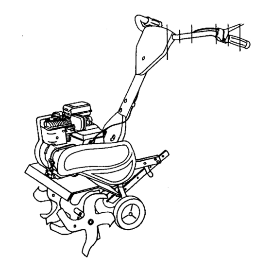
UNPACK CARTON & INSTALL Engine Bracket Halves HANDLE Nut =A" ,_CAUTION: Be careful of exposed sta- Depth Stake ples when handling or disposing of carton- ing material. IMPORTANT: When unpacking and as- sembling tiller, be careful not to stretch or kink cable(s). - Page 7 KNOW YOUR TILLER READ THIS OWNER'S MANUALAND SAFETY RULES BEFORE OPERATING YOUR TILLER. Compare the illustrations with your tiller to familiarize yourself with the location of vari- ous controls and adjustments. Save this manual for future reference. These symbols may appear on your Tiller or in literature supplied with the prod-...
- Page 8 The operation of anytiller can resultin foreign objects thrown into the eyes, which can result in Severe eye damage. Always wear safety glasses or eye shields before starting your tiller and while tilling. We recommend a wide vision safety mask over spectacles or standard safety glasses.
- Page 9 TO START ENGINE • Tilt tiller back on its wheels and then re- level. _CAUTION: Keep line control in "OFF" • With engine level, refill to point of over- position when starting engine. flowing if necessary. Replace oil filler When starting engine for the first time or if plug.
- Page 10 • Startengine,tip tinesoff groundby You will find tilling much easier if you pressinghandlesdown andengageline leave a row untilled between passes. controlto start line rotation.Allowtines Then go back be,tween tilled rows.There to rotate for five minutes. are two reasons for doing this. First, •...
- Page 11 MA,N,ENANC SCHEDULE , ',.OATES LO . Z SERV'CEOATES AS YOU COMPLETE nEOO nSE°V,CE Check EngineOil Level Change Engine Oil _1,2 Oil Pivot Points Inspect Spark Arrester/Muffler Inspect Air Screen Clean or Replace Air Cleaner Cartridge i_ 2 Clean Engine Cylinder Fins Replace Spark Plug 1 - Change more olten when operating under a heavy lOad o_ in high amblont temperatures.
-
Page 12: Air Cleaner
• Refill engine with oil. See =FILL Disconnect spark plug wire before per- forming any maintenance (except carbure- ENGINE WITH OIL" in the Operation tor adjustment) to prevent accidental start- section of this manual. ing of engine. Prevent firest Keep the engine free of Oil Drain grass, leaves, spilled oil, or fuel. -
Page 13: Spark Plug
SPARK PLUG Cylinder Fins Replace spark plugs at the beginning Muffler \ Blower each tilling season or after every 50 hours of use, whichever comes first. Spark plug type and gap setting isshown in "PROD- UCT SPECIFICATIONS" on page 4 of this manual. -
Page 14: Tine Operation Check
NARROW TILLING/CULTIVATING NOTE: If =ON" position check required 12-3/4" PATH adjustment, recheck "OFP position adjustment to insure tines do not rotate • Remove outer tines. when control is _OFP (up). netr Positiion line Control _, \ "ON" Position " Inner Tines Only "line Control Cable NOTE: When reassembling outer tines,... - Page 15 IDLE RPM ADJUSTMENT Be sure belt is positioned on inside groove of both pulleys, inside all belt • To adjust idle RPM, rotate throttle link- guides and rests on idler pulley. age counterclockwise and hold against CHECK TINE OPERATION stop while adjudting idle speed adjusting screw to obtain 1750 RPM.
-
Page 16: Engine Oil
NOTE: Fuel stabilizt_r is an acceptable Immediately prepare your tiller for storage at the end of the season or if the unit will alternative in minimizing the formation not be used for 30 days or more. fuel gum deposits during storage. Add sta- bilizer to gasoline in fuel tank or storage _,CAUTION:... - Page 17 PROBLEM CAUSE CORRECTION Will not start 1. Out of fuel. 1. Fill fuel tank. 2. See "TO START ENGINE" in.the 2. Engine not "CHOKED" properly. Operation section. 3. Wait several minutes before 3. Engine flooded. attempting to start. 4. Dirty air cleaner. 4.
- Page 18 CORRECTION PROBLEM CAUSE 1. Low oil level/dirty oil 1. Check oil level/change oil. Engine overheats 2. Dirty engine air screen. 2. Clean engine'air screen. 3. Clean cylinder fins, air screen, muf 3. Dirty engine. tier area. 4. Remove and clean muffler. 4.
-
Page 19: Repair Parts
REPAIR PARTS TILLER - - MODEL NUMBER 917.292390 HANDLE ASSEMBLY • PART PART DESCRIPTION DESCRIPTION 72010520 Bolt5/16-18 X 2-1/2 165197 Clip, Cable 137118 Panel, Control 110514X Assembly, Panel and Tube 152094 Assembly, Handle Column 98000129 Nut, Flange 9266R Grip, Handle STD533107 Bolt, Carriage 5/16-18 x 3/4 3066J... - Page 20 REPAIR PARTS TILLER - - MODEL NUMBER 917.292390 BELT GUARD AND PULLEY ASSEMBLY PART PART DESCRIPTION DESCRIPTION Ring, Retainer Screw Set 5/16.18 x 3/8 Patch 120(X)028 23230506 Sheave, Transmission Sheave, Engine 151223 130812 Nut J Clip #8 Screw, Hex Washer sn_, 165504 166361 Ring, Klip...
- Page 21 REPAIR PARTS TILLER o- MODEL NUMBER 917.292390 WHEEL AND DEPTH STAKE ASSEMBLY 1_ 2o • v PART PART DESCRIPTION DESCRIPTION 9194R Pin, Clevis 5388J Spdng, Stake 74760520 Bolt, HexHead 5/16-18 x 1-1/4 121117X Bolt, Shoulder STD523107 Bolt, HexHead 5/16-18x3/4 9188R Wheel STD541031 Nut, Hex 5/16-18...
-
Page 22: Tine Assembly
REPAIR PARTS TILLER - - MODEL NUMBER 917.292390 TINE ASSEMBLY PART PART DESCRIPTION DESCRIPTION 1 _56926 Tine,Outer,R.H. 4 156923 _ne, Inner, L.H. 163552 Retainer, Spdng Zinc 5 156925 ]3he, Outer, L.H. 156924 _ne, Inner,RH. 6 4929H Pin, Clevis... - Page 23 REPAIR PARTS TILLER - - MODEL NUMBER 917.292390 TRANSMISSION PART PART DESCRIPTION DESCRIPTION 74760524 Bolt, Hex 5/16-18 x 1-1/2 Gn 2 STD541431 Nut, Hex, Keps 5/16-18 UNC STD523732 Bolt, Fin, Hex 3/8-16 x 3-1/4 19091412 Washer 9/32 x 7/B x 12 Gauge STD551037 Washer 9/32 x 1-1/4 x 16 Ga, Washer...
- Page 24 REPAIR PARTS TILLER "" MODEL NUMBER 917.292390 DECALS PART DESCRIPTION 166216 Decal, Logo 166214 Decal, Logo 166215 Decal, 5HP/24" 137539 Decal, Caution,'nne Control 120431X Decal, Hand Placement 110719X Decal,Operationand Lubrication 120075X Decal, Warning, Rotating'13ne 165279 Decal, Engine 168975 Decal, 5.5t"1P 11 162215 Decal, "13ne Shield (Wrog Dora) 166217...
- Page 25 REPAIR PARTS TILLER - - MODEL NUMBER 917.292390 BRIGGS & STRATTON ENGINE - MODEL NUMBER 13720_Z,TYPE NO.1124-E1 36 35 _527 Z5001 "JkREQUIRES SPECIAL TOOLS TO INSTALL SEE REPAIR INSTRUCTION MANUAL.
-
Page 26: Repairparts Tiller
REPAIRPARTS TILLER - - MODEL NUMBER 917,292390 BRIGGS & STRATTON ENGINE - MODEL NUMBER 137202, TYPE NO.1124-E1 621_... - Page 27 REPAIR PARTS TILLER - - MODEL NUMBER 917.292390 BRIGGS & STRATTON ENGINE - MODEL NUMBER 137202, TYPE NO.1124-E1 358 GASKET SET 4SS_ 373_ 6s _' 1095 VALVE OVERHAUL GASKET SET 1036 LABEL KIT-EMISSION...
- Page 28 REPAIR PARTS TILLER - - MODEL NUMBER 917.292390 BRIGGS & STRA'n'ON ENGINE - MODEL NUMBER 137202,TYPE NO.1124-E1 PART PART DESCRIPTION DESCRIPTION 497144 Cylinder Assembly 93312 Retainer,Intake Valve and 399268 Bushing,Cylinder Exhaust Spring 299819 *Seal, Oil 260642 Tappet, Valve 214040 Head, Cylinder 214726 Gear, Cam 272157...
- Page 29 REPAIR PARTS TILLER - - MODEL NUMBER 917.292390 BRIGGS & STRATTON ENGINE -- MODEL NUMBER 13720;_, TYPE NO.1124-E1 PART PART DESCRIPTION DESCRIPTION 280720 Bell Crank 231550 Tube, Breather 231520 Screw, Shoulder 67838 Grommet, Braather Tube 262279 Rod, Speed Control 491435 Filter,Air 262948 Spring, Govemor...
- Page 30 For in-home major brand repair service: Call 24 hours a day, 7 days a week 1-800-4-MY-HOME _M (1-800-469-4663) Para pedir servicio de reparacibn a domicilio 1-800-676-5811 In Canada for all your service and parts needs call Au Canada pour tout le service ou les pieces 1-800-665-4455 For the repair or replacement parts you need: Call 6 am-11pm CST, 7 days a week...
Need help?
Do you have a question about the 917.292390 and is the answer not in the manual?
Questions and answers