
Related Manuals for Epson Photo750


Summary of Contents for Epson Photo750
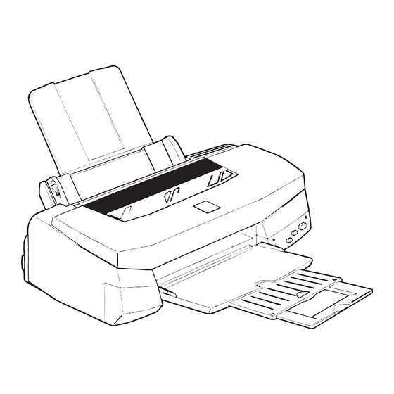
- Page 1 6(59,&(#0$18$/ 6(59,&(#0$18$/ 6(59,&(#0$18$/ 6(59,&(#0$18$/ Color Inkjet Printer EPSON Stylus Photo 750 ® SEIJ98005...
- Page 2 SEIKO EPSON CORPORATION. † All effort have been made to ensure the accuracy of the contents of this manual. However, should any errors be detected, SEIKO EPSON would greatly appreciate being informed of them.
- Page 3 2. MAKE CERTAIN THAT THE SOURCE VOLTAGES IS THE SAME AS THE RATED VOLTAGE, LISTED ON THE SERIAL NUMBER/ RATING PLATE. IF THE EPSON PRODUCT HAS A PRIMARY AC RATING DIFFERENT FROM AVAILABLE POWER SOURCE, DO NOT CONNECT IT TO THE POWER SOURCE.
-
Page 4: Symbols Used In This Manual
This manual describes basic functions, theory of electrical and mechanical operations, maintenance and repair procedures of EPSON Stylus Photo 750. The instructions and procedures included herein are intended for the experienced repair technicians, and attention should be given to the precautions on the preceding page. -
Page 5: Revision Status
Revision Issued Date Rev. A December 14, 1998 Rev. B July 30, 1999 Revision Status First Release Revise Page 85, 106 Description... -
Page 6: Table Of Contents
Troubleshooting Overview ... 39 Unit Level Troubleshooting... 41 Unit Repair (Power Supply Board) ... 44 Repair of the Control Board... 45 Unit Repair (Printer Mechanism) ... 47 Disassembly and Assembly Overview ... 51 Precautions ... 51 Tools ... 51 Work Completion Check ... 52 Disassembly ... - Page 7 Stylus Photo 750 Paper Gap Adjustment ... 78 Adjustment by Adjustment Program ... 80 Adjustment Program... 80 Setting Destination Information ... 82 Head Voltage ID Adjustment ... 83 Head Angular Adjustment ... 84 Bi-D Adjustment ... 86 Head Cleaning... 87 Initial Ink Charge ...
-
Page 8: Product Description
& + $ 3 7 ( 5 PRODUCT DESCRIPTION... -
Page 9: Overview
EPSON Stylus Photo 750 1.1 Overview This printer has better mechanism for the print quality and paper feeding than that of Stylus Photo and Stylus Photo 700. It also uses new print head and improved printing speed and through put. -
Page 10: General Description
EPSON Stylus Photo 750 1.2 General Description 1.2.1 Printing PRINTING METHOD † On demand ink jet NOZZLE CONFIGURATION † 48 nozzles x 6 (Black, Cyan, Magenta, Yellow, Light Cyan, Light Magenta) Figure 1-2. Nozzle Configuration PRINTING DIRECTION † Bi-direction with logic seeking... -
Page 11: Paper Feeding
EPSON Stylus Photo 750 TYPEFACE † Bin map LQ font: EPSON Courier, 10 CPI 1.2.2 Paper Feeding † Feeding Method: Friction feed with ASF † Paper Path: Cut-sheet ASF(Top entry) † Feeding Speed: 2.36 inches/sec (normal speed mode/continuous feeding) 4.5 inches/sec (high-speed mode/continuous feeding) 1.2.3 Paper Specification... -
Page 12: Printable Area
EPSON Stylus Photo 750 1.2.4 Printable Area † Cut Sheet The figure below shows printable area. Figure 1-3. Printable Area Product Description Table 1-3. Printable Area Paper Paper Paper Size Width Length (typ) (typ.) 210mm 297mm (8.3”) (11.7”) 216mm 279mm Letter (8.5”) -
Page 13: Adjust Lever Settings
3mm(0.12”) 3mm(0.12”) 3mm(0.12”) Figure 1-4. Printable Area Product Description 1.2.5 Adjust Lever Settings The adjust lever located under the printer cover(right side) needs to be set for the proper paper setting according to the paper type. TM(Top BM(Bottom margin) margin) (min.) -
Page 14: Environmental Conditions
EPSON Stylus Photo 750 1.2.6 Environmental Conditions † Temperature: „ Operating: 10 to 35 C(*3) „ Non-operating: -20 to 60 C(*1) NOTE: 1 month at 40 C and 120 hours at 60 C † Humidity: „ Operating: 20 to 80% RH(*2,*3) „... -
Page 15: Ink Cartridge
EPSON Stylus Photo 750 1.2.7 Ink Cartridge 1.2.7.1 Black Ink Cartridge † Type: Exclusive cartridge † Color: Black † Print capacity: 540 pages/A4 (ISO/IEC1056 1 Letter Pattern at 360 dpi) † Ink life: 2 years from production date † Storage temperature:-20 C to 40 C(Storage within a month at 40 C) -
Page 16: Input Data Buffer
EPSON Stylus Photo 750 1.2.8 Input Data Buffer † Buffer: 256 Kbytes 1.2.9 Electric Specification † 120V version „ Rated voltage: AC 120V „ Input voltage range: AC 99 -132V „ Rated frequency range:50 - 60Hz „ Input frequency range:49.5-60.5 Hz „... -
Page 17: Ce Marking
EPSON Stylus Photo 750 1.2.13 CE Marking † 220-240 V version „ Low Voltage Directive 73/23/EEC:EN60950 „ EMC Directive 89/336/EEC: EN55022 Class B EN61000-3-2 EN61000-3-3 EN50082-1 1.2.14 Printer Language and Emulation † Printer Language: ESC/P Raster EPSON Remote 1.2.14.1 ESC/P Control Codes <... - Page 18 EPSON Stylus Photo 750 „ Dot size control: ESC (e „ Raster header: ESC (D „ Raster body: ESC i † Color: „ Printing Color: ESC r, ESC (r † EEPROM control: „ EEPROM control: ESC Product Description General Description...
-
Page 19: Parallel Interface
-During -INIT signal is at low level or during hardware initialization -During printer error (See-ERROR signal) -When the parallel interface is not selected. Product Description ERROR signal is at low level when the printer is in one of the following states. -Printer hardware error (fatal error) -Paper-out error... -
Page 20: Parallel Interface(Reverse Channel)
† Extensibility request: The printer responds affirmatively when the extensibility request values are 00H or 04H, that mean, 00H: 04H: † Device ID: The printer sends following device ID string when it is requested. „ When IEEE1284.4 protocol is effective: [00H] [57H] MFG:EPSON;... - Page 21 EPSON Stylus Photo 750 „ When IEEE1284.4 protocol is NOT effective: [00H] [57H] MFG:EPSON; CMD:ESCPL2,BDC; MDL:Stylus[SP]Photo[SP]750; CLS:PRINTER; DES:EPSON[SP]Stylus[SP]Photo[SP]750; NOTE: [00H] denotes a hexadecimal value of zero. [SP] denotes a space character(20H). MDL and DES values depend on the EEPROM setting.
- Page 22 GND level. Also, these cables are shielded wires and it is effective means to connect to each chassis GND in the PC and printer for electrostatic noise. 2.Conditions for interface are based on TTL level. Rise and fall time should be within 0.2 s.
-
Page 23: Serial Interface
TxD+ Balanced Transmit+ Data terminal ready RxD+ Balanced Receive+ NOTE: In/Out refers to the direction of signal flow from the printer’s point of view. Product Description Following figure shows port arrangement of serial I/F connector. Specification Following table shows timing relation of DTR, X-ON/X-OFF handshaking. -
Page 24: Usb(Universal Serial Bus) Interface
EPSON Stylus Photo 750 1.3.4 USB(Universal Serial Bus) Interface Following shows specification. † Standard: Based on „ Universal Serial Bus Specifications Revision 1.0 „ Universal Serial Bus Device Class Definition for Printing Devices version 1.0 † Bit rate: 12Mbyte(Full Speed Device) †... -
Page 25: Prevention Of Data Transfer Time-Out On The Host
To prevent hosts from acting this kind of time-out, the printer receives data very slowly, several bytes per minute, even if the printer is in busy state. This slowdown starts when the remaining input buffer is less than several hundreds of bytes. -
Page 26: Function
EPSON Stylus Photo 750 1.4 Function 1.4.1 Control Code This printer is operated with the raster graphics control code based on the ESC/P2 control line. Refer to “ESC/PV2 Reference Manual” and “ESC/P2 specification” for each command and ESC sequence. 1.4.2 Bi-directional Command †... -
Page 27: Special Setting Mode
Lights during no Color ink condition, and blinks during the Color ink low condition. See the table on the next page for more detailed LED indications. Since LED indicates the various errors and current printer operations, LED indications enable to find out the proper repair operation. Function... -
Page 28: Errors
† Ink Out When the printer runs out most of the ink of any one color, it indicates ink-low warning and keeps printing. When the print runs out the whole ink of any one color, it indicates ink-error and stops printing. -
Page 29: Initialization
„ Clear the print buffer „ Set default values † Operator initialization This printer initializes itself when it is turned off and is turned on again within 10 seconds, or when it recognizes the -INIT signal(negative pulse) on parallel interface. On this initialization, following actions are performed. -
Page 30: Initialization Setting
EPSON Stylus Photo 750 1.4.8 Initialization Setting This printer initializes following settings as initialization setting when the initialization is performed. Also, among the items of panel setting, default setting and remote command settings, the items which can be stored are also initialized as initialization setting. -
Page 31: Consumables And Options
EPSON Stylus Photo 750 1.4.10 Consumables and options The consumables and options for this printe are following; Table 1-20. Consumables Classification IC1BK02 Consumables IC5CL02 Product Description Name Ink Cartridge(black) Ink Cartridge(color) Function Revision A... -
Page 32: Operating Principles
& + $ 3 7 ( 5 OPERATING PRINCIPLES... -
Page 33: Overview
Roller, Paper Feed Roller Line and Paper Guides. † Hopper Drive Mechanism This mechanism is installed at the rear side of the printer and consists of Paper Pick Up Roller, One-way Clutch and Hopper. Operation is performed by the PF motor, when the carriage is around the left edge. - Page 34 EPSON Stylus Photo 750 † Pump Mechanism This mechanism consists of Pump and Cap parts. „ Cap Parts This protects the surface of print head nozzle from being dry or from being attached with dust. „ Pump Parts This part receives motive power from the PF motor and absorbes bubbles and viscous ink on the print head nozzle by using the motor rotation and drains them to the waste ink pad.
-
Page 35: Operating Principles Of Electric Circuit
+42VDC +5VDC In this printer, even if the power switch is turned off in the middle of the printing operation, application of the secondary switch enables the printer to supply the voltage to the power/logic lines at the main board side for at least 30 seconds. - Page 36 EPSON Stylus Photo 750 +42 VDC +5 VDC ZD53 +5VDC Line Over Voltage IC51 Limitation +5V Regulator ZD52,87 +42VDC Line Over Voltage Limitation ZD81-86,ZD51 +42VDC Line Constant Control C84,Q84 Power Drop Delay Circuit Smoothing Circuit TRANS(T1) Smoothing Main Switching Circuit...
-
Page 37: C259 Main Control Circuit
EPSON Stylus Photo 750 2.2.2 C259 Main Control Circuit Printer mechanism is controlled by C259 main board. The figure below shows the block diagram of C259 main control circuit. CN3 USB Cartridge Sensor P-ROM (IC3) Head Batt1 D-RAM (IC4) CN1 Parallel... -
Page 38: Reset Circuit
EPSON Stylus Photo 750 2.2.2.2 Reset Circuit Reset circuit consists of reset/timer IC(IC8) and peripheral elements. The reset/timer IC prevents the CPU from running away, which is caused by the unstable voltage(+5VDC line voltage is less than +4.3V) in the logic line during the power ON/OFF operation. Also, IC sends the reset signal to the CPU and gate array when +42VDC line voltage is less than +35.5V. - Page 39 † PE Sensor PE sensor uses the photo interrupter method. A PE sensor determines if there is a paper in the printer. Based on the signal from this sensor, a particular page edge treatment such as Micro- weave printing is performed.
-
Page 40: Timer Circuit
2.2.2.4 Timer Circuit The timer of this printer uses reset/timer IC(IC8). The timer keeps record of how long the printer is OFF and uses it information to judge it the initial cleaning should be performed or not when the power it turned ON next time. - Page 41 EPSON Stylus Photo 750 † Driver on the head The driver on the head is Nozzle-selector drive circuit. Each drive waveform generated in the drive voltage wave form circuit is charged to the selected nozzle by this circuit with PZT elements, then, printing is performed.
- Page 42 EPSON Stylus Photo 750 2.2.2.8 Carriage Motor(CR Motor) Drive Circuit CR motor is driven by IC11 mounted on the C259 main control board. 4-phase 200-pole Hybrid type stepping motor is used as a CR Motor and is driven by bi-pola constant drive control.
-
Page 43: Troubleshooting
& + $ 3 7 ( 5 TROUBLESHOOTING... -
Page 44: Overview
3.1 Overview This section describes how to identify and troubleshoot the problems when repairing the printer by dividing the troubles into two levels; repair and replacement of the assemblies and units, and repair of the components. Refer to the flowchart below and perform repairing the component after separating the defective units. - Page 45 EPSON Stylus Photo 750 Table 3-3. Error Indication LED Indication Condition Paper Ink End Power Check (Black) No Paper Paper Jam Blink Ink End / No Cartridge (black) Ink End / No Cartridge (color) Ink Low (black) Blink Ink Low (color)
-
Page 46: Unit Level Troubleshooting
EPSON Stylus Photo 750 3.2 Unit Level Troubleshooting This section contains the flow charts which are used to isolate the faulty unit by following the flow chart according to the problem caused during replacing or repairing the unit. You are to identify the faulty unit based on the primary symptom listed in the Table3-4. - Page 47 EPSON Stylus Photo 750 Revision A 2. Error is detected. 3. Abnormal printing operation Figure 3-3. Flowchart 2 Figure 3-4. Flowchart 3 Troubleshooting Unit Level Troubleshooting...
- Page 48 EPSON Stylus Photo 750 Revision A 4. Paper feed operation is not performed correctly 5. Abnormal Control Panel Figure 3-5. Flowchart 4 Figure 3-6. Flowchart 5 Troubleshooting Unit Level Troubleshooting...
-
Page 49: Unit Repair (Power Supply Board)
EPSON Stylus Photo 750 3.3 Unit Repair (Power Supply Board) This section describes the problems related to the power supply board. The table below provides various symptoms, likely causes, and checkpoints. The checkpoints refer to waveforms, resistance, and other values to check to evaluate the operation of each component. -
Page 50: Repair Of The Control Board
EPSON Stylus Photo 750 3.4 Repair of the Control Board This section describes the problems related to the power supply board. The table below provides various symptoms, likely causes, and checkpoints. The checkpoints refer to waveforms, resistance, and other values to check to evaluate the operation of each component. - Page 51 EPSON Stylus Photo 750 Table 3-9. Repair of the Control Board Sympto Condition Cause Check point Check the signal waveform of DATA(Pin 29) of IC14 and Common NPNB/PNPB(Pin 16/19). Abnormal IC12 is printing broken. IC14 is broken. Troubleshooting Solution If DATA...
-
Page 52: Unit Repair (Printer Mechanism)
EPSON Stylus Photo 750 3.5 Unit Repair (Printer Mechanism) This section provides instruction for repairing mechanism. It describes various problems, symptom, likely causes, checkpoints, and solutions. Select appropriate symptom from the the table and check each parts and its function as describes in the checkpoint. - Page 53 EPSON Stylus Photo 750 Table 3-12. Repair of the Printing Mechanism Symptom Condition Cause Check visually if Head FFC is the head FFC on out of the board or connection. carriage is connected firmly. FFC is Check the FFC disconnected by using a tester.
- Page 54 EPSON Stylus Photo 750 Table 3-14. Repair of the Printer Mechanism Symptom Condition Cause Check Point A vertical Bi-directional Perform Bi-D line is not alignment is adjustment. aligned. not adjusted. Perform head Head angle is angle not correct. adjustment. Platen gap is Perform Platen not right.
-
Page 55: Disassembly And Assembly
& + $ 3 7 ( 5 DISASSEMBLY AND ASSEMBLY... -
Page 56: Overview
EPSON Stylus Photo 750 4.1 Overview This section describes procedures for disassembling the main components of EPSON Stylus Photo750. Unless otherwise specified, disassembly units or components can be reassembled by reversing the disassembly procedure. Precautions for any disassembly or assembly procedures are described under the heading “Caution”. -
Page 57: Work Completion Check
EPSON Stylus Photo 750 4.1.3 Work Completion Check If any service is made to the printer, use the checklist shown below, to confirm that all works are completed properly and the printer is ready to return to the user. Table 4-2. Check List... -
Page 58: Disassembly
EPSON Stylus Photo 750 4.2 Disassembly The flowchart below shows step-by step disassembly procedures. Figure 4-1. Flowchart Disassembly and Assembly Disassembly Revision A... -
Page 59: Housing Removal
Since this printer has no lower housing, the printer mechanism is exposed just by removing the upper housing. 1. Open the printer cover and set the PG adjust lever on the right-hand side to (+) position. 2. Remove 4 screws and remove the upper housing. -
Page 60: Circuit Boards Removal
Refer to “Check Point” and “Adjustment Required” on the next page. 1. Remove the upper housing. (“Housing Removal” on page -54) 2. Remove 5 screws securing the “Printer Mechanism” to the “Shield plate, M/B”. Figure 4-3. Shield Plate, M/B Removal 3. - Page 61 EPSON Stylus Photo 750 Unlock the connector CN6 and CN7 before disconnecting them. Also, be sure to lock them when reconnecting them. After replacing C259 Main Board, perform the following adjustments. 1. Head ID Writing (See “Head Voltage ID Adjustment” on page -83) 2.
-
Page 62: Control Panel Removal
2. Remove 2 screws securing the control panel, then remove the control panel from the printer mechanism. 3. Remove one screw securing the “Housing, Panel, Left” to the printer mechanism. 4. Remove 2 screws securing the “Board, Assembly, Panel” to the printer mechanism, then remove C209PNL board from the “Panel,... -
Page 63: Absorber Tray, Assembly;A Removal
4. Remove “Spacer Tray” securing “Absorber Tray, Assembly” at the left side of the printer mechanism and remove “Absorber Tray, Assembly;A” by pulling it downward. Be sure to reset the waste ink counter, when replacing the “Absorber Tray, Assembly;A”... -
Page 64: Printer Mechanism Removal
4.2.5.1 Print Head Removal 1. Remove the upper housing.(See “Housing Removal” on page -54) 2. Rotate “Gear, 67.2” toward the front side of the printer and release the carriage lock mechanism. Then, move the carriage assembly to the left side. -
Page 65: Adjustment
„ When you return the printer to the user, pack the printer in the state that the ink cartridges are installed in the printer and carriage is in the home position. - Page 66 4. Loosen 2 screws and disengage the “Frame, Assembly, Exit” and side frame. 5. Sand up the printer mechanism so that you can see the bottom of the printer mechanism. 6. Remove one hook securing the “Cap Assembly” at the right side of the frame, and release the engagement with the frame by lifting up the right side of “Cap Assembly”.
- Page 67 EPSON Stylus Photo 750 „ Since there is a spring inside the pump assembly, be careful of the spring popping out. „ When assembling, be careful not to pinch or give pressure to the ink tube, which is connected between “Pump, Assembly” and “Cap, Assembly”.
-
Page 68: Adjustment
4.2.5.3 Motor, Assembly, CR Removal 1. Remove the upper housing.(See “Housing Removal” on page -54) 2. Rotate “Gear, 67.2” toward the front of the printer and disengage the “Carriage Lock Mechanism”. Then, move the carriage to the center of the platen. - Page 69 EPSON Stylus Photo 750 4.2.5.4 Motor Assembly PF Removal 1. Remove the upper housing.(See “Housing Removal” on page -54) 2. Remove “Absorber Tray, Assembly;A”. (See “Absorber Tray, Assembly;A Removal” on page -58) 3. Remove the following gears which are located at the left side of the printer mechanism.
- Page 70 EPSON Stylus Photo 750 4.2.5.5 ASF, Assembly Removal 1. Remove the upper housing.(See “Housing Removal” on page -54) 2. Release the hook and remove “Gear,34” from the roller shaft of “ASF, Assembly”. 3. Remove the cable from a hook of “ASF Assembly” and cable hook of the “Printer Mechanism”.
- Page 71 EPSON Stylus Photo 750 4.2.5.6 Paper Feed Roller Assembly Removal 1. Remove “ASF, Assembly”. (See “ASF, Assembly Removal” on page -65) 2. Remove “Torsion Spring,41.2” by unhooking one end from the ASF frame and remove “Lever, Brake”. 3. Remove “Bush, Fixing, Shaft” from the right end of “Shaft, Roller, LD”...
- Page 72 EPSON Stylus Photo 750 4.2.5.7 Roller Assembly, LD Left/Right Removal 1. Remove “ASF, Assembly”. (See “ASF, Assembly Removal” on page -65) 2. Remove right and left “Compression Spring, 1.66” from the back of “Hopper, Assembly”. 3. Pull out the cam part of “Hopper, Assembly” through the hole of the right frame of “Paper Feed, Roller Assembly, Right”.
- Page 73 EPSON Stylus Photo 750 4.2.5.8 Carriage Assembly Removal 1. Remove the upper housing.(See “Housing Removal” on page -54) 2. Push “Holder, Pulley, Driven” to loosen the timing belt and detach the timing belt from the pulley of CR motor assembly.
-
Page 74: Adjustment
EPSON Stylus Photo 750 When installing the spring washer, convex side should be facing to the “Bush, Parallel Adjust, Right”. Be careful not to install in wrong direction. Perform following adjustments, after replacing or removing “Carriage Assembly”. „ Paper Gap Adjustment (See “Paper Gap Adjustment”... - Page 75 EPSON Stylus Photo 750 4.2.5.9 PE Sensor Assembly Removal 1. Remove the upper housing.(See “Housing Removal” on page -54) 2. Release 2 hooks from the frame surface and remove “PE Sensor Assembly” by sliding it. When installing the PE Sensor Assembly, be sure that the sensor lever is correctly inserted into a hole of “Paper Guide Assembly”.
- Page 76 -68) 3. Remove “PE Sensor Assembly”. (“PE Sensor Assembly Removal” on page -70) 4. Remove 2 screws securing “Guide board, Cable” to the printer mechanism, then remove “Guide Board, Cable”. Figure 4-22. “Paper Guide, Assembly” Removal Disassembly and Assembly 5.
- Page 77 EPSON Stylus Photo 750 9. Move the whole “Roller, Assembly, PF” to the left direction, and remove the “Roller, Assembly, PF”. „ When reinstalling “Paper Guide, Assembly, Upper” at the right edge, be careful not to damage the “PE Sensor Lever”.
- Page 78 EPSON Stylus Photo 750 4.2.5.11 HP Sensor Removal 1. Remove the upper housing. (“Housing Removal” on page -54) 2. Disconnect the cable from “HP Sensor” and remove it by releasing its hook. Figure 4-25. HP Sensor Removal Disassembly and Assembly...
- Page 79 EPSON Stylus Photo 750 4.2.5.12 Cartridge Sensor(Sensor, I/C) Removal 1. Remove one screw securing “Bush Holder, Sensor, I/C” to the carriage assembly, and remove it. Bush Holder, Screw Sensor, I/C Figure 4-26. Bush Holder, Sensor, I/C Removal 2. Remove “Harness, I/C” from the clamp part of the carriage.
- Page 80 EPSON Stylus Photo 750 Carriage Assembly Sensor, I/C Engaging parts at the carriage side Hooks Figure 4-29. Sensor, I/C Removal 5. Separate “Sensor, IC” from the harness by releasing its connection. „ Be careful of the direction of sensor, when installing it.
-
Page 81: Adjustment
& + $ 3 7 ( 5 ADJUSTMENT... -
Page 82: Overview
5.1.1 Required Adjustment Table 5-1 lists all the necessary adjustments for this printer. If any service listed in this table is carried out, all adjustments corresponding to that service should be performed to ensure proper operation of the printer. -
Page 83: Adjustment
This section describes the detailed procedures of each adjustment. 5.2.1 Paper Gap Adjustment When replacing the carriage assembly or removing it during printer mechanism disassembly, perform the paper gap adjustment during assembling and get the standard distance from the surface of the printing head to the paper surface. - Page 84 EPSON Stylus Photo 750 6. From this thickness with which the thickness gauge stars moving with the carriage, move the gear of the “Bush, Parallel, Adjustment one notch forward you. (Gap will be narrowed) At this time, make sure that the thickness gauge does not move.
-
Page 85: Adjustment By Adjustment Program
EPSON Stylus Photo 750 5.3 Adjustment by Adjustment Program In this printer, it is necessary to set the correct information for each printer mechanism in order to maintain consistent printing function and quality, eliminating difference of each printer mechanism’s characteristics. Therefore, in case that the combination of the printer... - Page 86 EPSON Stylus Photo 750 6. Select “World”. 7. Select “Perform”, if “Printer is not ready” message is not indicated. After this screen, menu screen will appear. Each function on the main menu can be executed by ESC and ENTER keys.
-
Page 87: Setting Destination Information
EPSON Stylus Photo 750 5.3.2 Setting Destination Information 1. Select “Adjustment” on the main menu and press Return key. Program goes to the adjustment menu. 2. Select “Market Destination Check” and press Return key. 3. The screen shows “Checking the present Market Destination”. -
Page 88: Head Voltage Id Adjustment
You can find VH voltage ID on the following position: „ Print Head: „ Printer mechanism: On the label of the packing box of the printer 5. After completing the Head ID input, press ESC key until the screen returns to the adjustment menu. -
Page 89: Head Angular Adjustment
EPSON Stylus Photo 750 5.3.4 Head Angular Adjustment During production, slight variations are created in print heads and carriage (which are used as a print head base). If these differences are not adjusted, they can adversely influence the print head angle, and result in the poor print quality. - Page 90 EPSON Stylus Photo 750 5. Refer to the printing pattern, and adjust the head angle by using the adjustment lever. Figure 5-5. Lever Operation and Corresponding Change in Pattern „ When performing the head angular adjustment, select “Move the carriage to the head angular adjustment position”...
-
Page 91: Bi-D Adjustment
EPSON Stylus Photo 750 5.3.5 Bi-D Adjustment This adjustment is to correct differences in printing positions, which is caused by slippage of printing timing in right and left directions during the Bi-directional printing. The value adjusted in this section will be stored as Bi-D corrected value in the EEPROM on the control board. -
Page 92: Head Cleaning
EPSON Stylus Photo 750 5.3.6 Head Cleaning In this function, the same cleaning as the one from the control panel can be performed from the adjustment program. With this sequence, you can forcibly solve the clogged nozzle problem caused by viscous ink. -
Page 93: Initial Ink Charge
EPSON Stylus Photo 750 5.3.7 Initial Ink Charge There is no ink charged in the ink path of a spare print head and printer mechanism. Therefore, after you replace any of the following units, perform initial ink charge and return the printer after making sure that ink is ejected correctly from the print head. -
Page 94: Counter Value For Ink Absorber
EPSON Stylus Photo 750 5.3.8 Counter Value for Ink Absorber This function is for indicating the protection counter value for the waste ink absorber and resetting the counter value. This function can be also performed from the control panel. (See “Special Setting Mode” on page -22) 5.3.8.1 Protect Counter Value... -
Page 95: Maintenance
& + $ 3 7 ( 5 MAINTENANCE... -
Page 96: Overview
The printer has a built-in head cleaning function and is activated through the control panel operation. 1. Confirm that the printer is in stand-by state(the Power indicator is not blinking), and press “Cleaning” button. 2. The printer enters the built-in cleaning sequence, and head cleaning is performed. -
Page 97: Lubrication
EPSON Stylus Photo 750 6.1.3 Lubrication The type and amount of oil and grease used to lubricated the printer parts are determined based on the results of internal evaluations. Therefore, be sure to apply the specified type and amount of oil and grease to the specified part of the printer mechanism during servicing. - Page 98 EPSON Stylus Photo 750 Table 6-3. Lubrication Point Lubrication Type/Point • Rotate gears after applying <Lubrication Amount> • 1/4 of gear tooth for “Gear, 67.2” • Use a syringe to apply it. • 1/3 of gear tooth for “Combination Gear, 16,21.6”...
- Page 99 EPSON Stylus Photo 750 Revision A Maintenance Overview...
- Page 100 EPSON Stylus Photo 750 Revision A Maintenance Overview...
-
Page 101: Appendix
& + $ 3 7 ( 5 APPENDIX... -
Page 102: Connector Summary
EPSON Stylus Photo 750 7.1 Connector Summary 7.1.1 Major Component Unit Major component unit of this printer is as follows. † Control Board (C259 MAIN or C264 MAIN) † Power Supply Board (C257 PSB/C257 PSE) † Control Panel (C209PNL) † Printer Mechanism (M-4M11) The figure below shows how these components are connected. - Page 103 EPSON Stylus Photo 750 Table 7-3. Connector CN5 Signal Name Sensor detect signal Ground Sensor Power Supply Table 7-4. Connector CN6 Signal Name Sensor detect signal Ground ASFV Sensor Power Supply Table 7-5. Connector CN7 Signal Name Phase drive signal (A)
- Page 104 EPSON Stylus Photo 750 Table 7-8. Connector CN9 Signal Name Ground NCHG All Head On Pulse Output Ground Logic power supply (+5V) GND2 Ground GND2 Ground GND2 Ground GND2 Ground Head Drive Power Supply Head Drive Power Supply Head Drive Power Supply...
-
Page 105: Component Layout
EPSON Stylus Photo 750 Revision B 7.2 Component Layout Figure 7-3. C259 Main Component Layout (Soldered Side) Figure 7-2. C259 Main Component Layout Appendix Component Layout... - Page 106 EPSON Stylus Photo 750 Revision B Figure 7-5. C257PSB/C257PSK Component Layout Figure 7-4. C257PSB Component Layout Appendix Component Layout...
-
Page 107: Exploded Diagram
EPSON Stylus Photo 750 7.3 Exploded Diagram Following pages shows exploded diagram of Stylus Photo 750. EXPLODED DIAGRAM FOR EPSON STYLUS PHOTO 750 (1/3) Appendix for EAI for ETT For EUR,S.E.ASIA, Figure 7-6. Exploded Diagram-1 Exploded Diagram for EAI, LATIN... - Page 108 EPSON Stylus Photo 750 EXPLODED DIAGRAM FOR EPSON STYLUS PHOTO 750 (2/3) Appendix Figure 7-7. Exploded Diagram 2 Exploded Diagram Revision B...
- Page 109 EPSON Stylus Photo 750 (501) 542 544 542 544 542 544 EXPLODED DIAGRAM FOR EPSON STYLUS PHOTO 750 (3/3) Appendix (506) Figure 7-8. Exploded Diagram 3 Exploded Diagram (565) 564 562 (505) Revision B...
-
Page 110: Electric Circuit
EPSON Stylus Photo 750 7.4 Electric Circuit Next pages shows the following electric circuits. † C259(or C264) MAIN Control Circuit † C257 PSB Power Supply Circuit † C257 PSE Power Supply Circuit † C257 PSE Power Supply Circuit (for Korea)
Need help?
Do you have a question about the Photo750 and is the answer not in the manual?
Questions and answers