Greenheck MSX Installation, Operation And Maintenance Manual
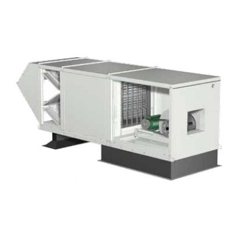
Make-up air unit
Hide thumbs
Also See for MSX:
- Installation, operation and maintenance manual (20 pages) ,
- Installation, operation and maintenance manual (20 pages)
Table of Contents
Advertisement
®
®
Installation, Operation and Maintenance Manual
Please read and save these instructions. Read carefully before attempting to assemble, install, operate or maintain the
product described. Protect yourself and others by observing all safety information. Failure to comply with instructions
could result in personal injury and/or property damage! Retain instructions for future reference.
General Safety Information
Only qualified personnel should install this unit.
Personnel should have a clear understanding of these
instructions and should be aware of general safety
precautions. Improper installation can result in electric
shock, possible injury due to coming in contact with
moving parts, as well as other potential hazards.
Other considerations may be required if high winds
or seismic activity are present. If more information
is needed, contact a licensed professional engineer
before moving forward.
1. Follow all local electrical and safety codes, as well
as the National Electrical Code (NEC), the National
Fire Protection Agency (NFPA), where applicable.
Follow the Canadian Electric Code (CEC) in
Canada.
DANGER
Always disconnect power before working on or
near a unit. Lock and tag the disconnect switch or
breaker to prevent accidental power up.
CAUTION
When servicing the unit, motor may be hot enough
to cause pain or injury. Allow motor to cool before
servicing.
®
2. The rotation of the wheel is critical. It must be free
to rotate without striking or rubbing any stationary
objects.
3. Motor must be securely and adequately grounded.
4. Do not spin fan wheel faster than maximum
cataloged fan rpm. Adjustments to fan speed
significantly effects motor load. If the fan RPM is
changed, the motor current should be checked to
make sure it is not exceeding the motor nameplate
amps.
5. Do not allow the power cable to kink or come in
contact with oil, grease, hot surfaces, or chemicals.
Replace cord immediately if damaged.
6. Verify that the power source is compatible with the
equipment.
7. Never open blower access doors while the fan is
running.
IMPORTANT
All factory provided lifting lugs must be used when
lifting any unit. Failure to comply with this safety
precaution could result in property damage, serious
injury or death.
WARNING
Disconnect all electrical power to the fan and secure
to the "OFF" position prior to inspection or servicing.
Failure to comply with this safety precaution could
result in serious injury or death.
WARNING
Improper installation, adjustment, alteration, service
or maintenance can cause property damage,
injury or death. Read the installation, operating
and maintenance instructions thoroughly before
installing or servicing this equipment.
Part #470658
MSX
Make-Up Air Unit
Model MSX Make-Up Air
1
Advertisement
Table of Contents

Related Manuals for Greenheck MSX


Summary of Contents for Greenheck MSX
-
Page 1: General Safety Information
Part #470658 ® ® Make-Up Air Unit Installation, Operation and Maintenance Manual Please read and save these instructions. Read carefully before attempting to assemble, install, operate or maintain the product described. Protect yourself and others by observing all safety information. Failure to comply with instructions could result in personal injury and/or property damage! Retain instructions for future reference. -
Page 2: Inspection And Maintenance During Storage
Any physical damage to the unit after blocking to prevent it from settling into soft ground. acceptance is not the responsibility of Greenheck Fan Locate parts far enough apart to permit air circulation, Corporation. -
Page 3: Table Of Contents
Table of Contents Installation of Indoor Unit Installation 1. Install Hangers Clearance to Combustibles/Service Clearances . 3 Install threaded hangers from ceiling supports. When Indoor Unit ....... 3 locating hangers, allow enough room to open access Unit Arrangement DB / HZ / UB . - Page 4 Installation of NOTE Arrangement DB / HZ / UB The use of all lifting lugs and a set of spreader bars is mandatory when lifting the unit. 1. Install Curb and/or Equipment NOTE Support(s) Position curb/equipment support(s) on the roof Some units come with the weatherhood attached (reference the CAPS submittal for placement of curb/ and Step 5 may not apply.
-
Page 5: Roof Mounted Unit - Arrangement Dbc
Installation of Roof Mounted Unit 4. Apply Sealant Apply an appropriate sealant around the perimeter of Arrangement DBC the curb and duct adapter(s) to isolate fan vibration and prevent water penetration. 1. Install Curb/Equipment Support(s) Exhaust Position curb/equipment support(s) on the roof Ductwork Exhaust Duct by Others... -
Page 6: Optional Evaporative Cooling Module
7. Install Supply Unit Use a crane and a set of spreader bars hooked to the factory lifting lugs to lift and center the unit on the extension/equipment support(s). Use self-tapping sheet metal screws to fasten the unit to the extension/equipment support(s). Installing Supply Unit NOTE The use of all lifting lugs and a set of spreader bars... - Page 7 Installation of Evaporative Cooling 4. Secure Cooling Module to Unit Module (optional) Use self-tapping screws to fasten the cooling module to the base unit along the top and down both sides. Fasten at the top through the flanges. To fasten the sides, the NOTE media must be removed.
- Page 8 Installation of Electrical Wiring 1. Determine the Size of the Main Power Lines The unit’s nameplate states the voltage and the unit’s IMPORTANT MCA. The main power lines to the unit should be sized Before connecting power to the unit, read and accordingly.
-
Page 9: Electrical Wiring
Installation of Electric Heater Sizing of Supply Conductors The required minimum size of supply conductors (optional) is marked at the field wiring terminals within the heater control box or reference the Supply Wire Size WARNING table included in this section. The wire gauges are calculated for 125% of the heater line current as Electrical Shock Hazard! Disconnect all power required by the National Electric Code, Article 424-3(b) - Page 10 Installation Evaporative Cooler Piping (optional) Evaporative Cooling with Auto Drain and Fill Evaporative Cooling with Recirculating Pump Supply Supply Line Line Sump Overflow VALVE A Supply Supply Solenoid Line Valve (Normally (Normally Closed) Closed) Sump Drain Drain Line Valve VALVE C (Normally Open) Sump Drain Solenoid Overflow...
- Page 11 Evaporative Cooling with Auto Drain and Fill continued 1. Install the Water Supply Line Supply line opening requirements vary by unit size and arrangement and are field supplied. Connect the water supply line to the float valve through the supply line opening in the evaporative cooling unit.
- Page 12 Installation of Water Wizard (optional) To Media Pressure Factory Evaporative Cooling with the Water Wizard™ Gauge Installed Sump Drain NOTE Manual Supply Valve The following instructions are provided for evaporative coolers equipped with the Water Wizard™ only. Additional instructions are provided for evaporative Supply Solenoid Roof coolers equipped with the auto-drain and fill or...
- Page 13 Installation of Direct Expansion (DX) NOTE Coil Piping (optional) If a hot gas bypass kit was provided by others, refer to the manufacturer’s instructions. IMPORTANT 3. Install Suction Line Guidelines for the installation of direct expansion Install suction line(s) from the compressor to the cooling coils have been provided to insure proper suction connection(s) which are stubbed through the performance and longevity of the coils.
- Page 14 Installation of Chilled Water Coil for one minute, the system is ready to be charged or refrigerant in another portion of the system can be Piping (optional) opened to the coil. A steady rise in microns would indicate that moisture is still present and that the coil IMPORTANT should be further vacuumed until the moisture has been removed.
- Page 15 Installation of Building Pressure Control (optional) 1. Mount Pressure Tap Using the factory provided bracket, mount the pressure tap to the outside of the unit. Choose a location out of the prevailing winds and away from supply or exhaust fans to assure accurate readings.
-
Page 16: Blower
Start-Up - Blower 2. Check the Blower Rotation Open the blower access door Refer to the Start-Up Checklist in the Reference and run the blower momentarily section before proceeding further! to determine the rotation. Pre Start-Up Check Arrows are placed on the blower scroll to indicate the Rotate the fan wheel by hand and make sure no parts proper direction or reference... - Page 17 5. Air Volume Measurement & Check Measure the unit’s air volume (cfm) and compare it with it’s rated air volume. If the measured air volume is off, adjust the fan’s RPM by changing/adjusting the drive. NOTE The most accurate way to measure the air volume is by using a pitot traverse method downstream of the blower.
- Page 18 Start-Up - Electric Heater (optional) Refer to the Start-Up Checklist in the Reference section before proceeding further! Pre Start-Up Check Check all electrical connections. Tighten any loose connection to all components including contactors, heating elements and main power lugs. WARNING Disconnect and lock-out all power before performing any maintenance or service to the unit.
-
Page 19: Blower
Start-Up - Evaporative Cooling 8. Put the Unit into Service Remove the jumper, and energize the blower(s). Verify Recirculating (optional) proper operation. 1. Check the Installation IMPORTANT The media may have been removed during installation, so its orientation Check the media for minerals after two weeks of 45º... - Page 20 Start-Up - Water Wizard™ (optional) 5. Check Media Start the cooling cycle and check the media after one hour of operation. If the media is continuously dry or if too much water is draining from the sump tank, refer Function Key Up Key to Troubleshooting, Water Wizard™.
- Page 21 NOTE The Freeze Temperature is preset to the factory recommended 45°F. Steps 9-11 should only be completed if the Freeze Temperature needs adjustment. NOTE The Freeze Temperature is the temperature at which the supply solenoid closes and the drain solenoid opens to drain the supply line, preventing possible freeze damage.
- Page 22 Check Operation - VAV Units Building Pressure Control — BLOWER a variable frequency drive is EXHAUST (optional) (OPTIONAL) SUPPLY controlled according to input MAIN VALVES HEAT from a pressure sensing device. NOTE Turn both knobs to the upper DIRTY FILTERS Blower Start-Up, Steps 1-5 should be performed most pressure setting.
- Page 23 Check Operation - Recirculating Building Pressure Control — a BLOWER modulating spring return actuator EXHAUST Units (optional) (OPTIONAL) SUPPLY is used to control the return air MAIN VALVES HEAT amounts. The return air damper modulates from fully open to fully NOTE DIRTY FILTERS closed based on a signal from a...
- Page 24 Operation - Electrical differential switch (PDS), which closes when proper airflow is achieved Electrical Sequence • Power passes through N.C. automatic and manual reset temperature cutouts (A and 1. Exhaust Fan Contact (S1) Closed M), which remain closed if the maximum (optional) temperature has not been reached •...
- Page 25 Operation - Water Wizard™ (optional) Dry Bulb Temperature The dry bulb temperature is visible on the home screen. If a number is not visible, wait 15 seconds and use the Up and Down Keys until a number is Function Key Up Key displayed.
- Page 26 Troubleshooting Blower Does Not Operate Proper supply power at main disconnect Check main voltage (See Blower Start-Up Step #1) Main Disconnect (DS1) Off (Turn Main Disconnect DS1 On) Primary fuses blown (Replace fuses) 24 VAC between terminals R and X? Main Transformer (TR1) Defective (Replace transformer) 24 VAC between...
-
Page 27: Motor Overamps
Troubleshooting Motor Overamps Air volume too high? Adjust drives or increase external static pressure as needed. (Reference Blower Start-Up Step #5) Actual static pressure lower than design? Adjust drives to reduce blower RPM. (Reference Blower Start-Up Step #5) Blower rotation correct? Reverse blower rotation. -
Page 28: Insufficient / Too Much Airflow
Troubleshooting Insufficient Airflow Damper(s) not fully opened? Adjust damper linkage(s), or replace faulty actuator(s). (Damper actuators may take a few minutes to open) System static losses too high? Reduce losses by improving ductwork. Blower speed too low? Adjust drives as needed. (Reference Blower Start-Up Step #5) Filters dirty or clogged Clean or replace filters. -
Page 29: Excessive Noise Or Vibration
Troubleshooting Excessive Noise or Vibration Belts worn or loose? Replace worn belts or tighten loose belts. (Reference V-Belt Drive Maintenance in the Maintenance section) Sheaves aligned? Align sheaves. (Reference V-Belt Drive Maintenance in the Maintenance section) Wheel unbalanced? Clean and/or balance wheel(s). Bearings worn or need lubrication? Replace worn bearings or lubricate bearings as needed. - Page 30 Troubleshooting Electric Heater Does Not Operate (optional) Supply fan must be on for heater to operate 24 VAC between terminals W1 and X? Heat Switch (S4) Off (Turn Heat Switch (S4) On) Heat Switch not wired (Wire Heat Switch (S4)) 24 VAC between terminals 22 and 21? Main Transformer (TR2) defective...
- Page 31 Troubleshooting Evaporative Cooler does not Operate (Recirculating pump) Supply fan must be on for cooler to operate 24 VAC between terminals Cool Switch (S4) off Y1 and X (Turn Cool Switch (S4) on) Cool Switch not wired (Wire Cool Switch (S4)) 24 VAC between terminal A2 on Cooling Relay (RC) and X Optional Inlet Air Sensor (TS4) holding...
- Page 32 Troubleshooting Water Wizard™ — Improper Water Supply NOTE NOTE If the water supply is too low, the media will Changing the On Time Factor by (1) will change the continuously appear dry. water supply by approximately 3%. NOTE IMPORTANT If the water supply is too high, the media will be The enter key must be pressed to save the new On saturated and excessive water will be draining from Time Factor.
-
Page 33: Routine
Maintenance - Routine Snow Accumulation CAUTION Clear snow away from roof mounted units. Keep the Lock-out the gas and the electrical power to the snow clear of the intake and access doors. unit before performing any maintenance or service Motors operations to this unit. - Page 34 Maintenance - Routine continued Bearings Filters The bearings for Greenheck fans are carefully selected Filter maintenance is generally limited to cleaning and to match the maximum load and operating conditions replacement. of the specific class, arrangement and fan size. If aluminum mesh filters are installed, they can be The instructions provided in this manual and those washed in warm soapy water.
- Page 35 Maintenance - Routine continued Cooling Coils WARNING Repair and replacement of the coil and the connecting piping, valves, etc., should be performed by a qualified individual. Inspect the coil for signs of corrosion and/or leaks. Repair any leaks as required. Inspect the coil’s surface for foreign material.
-
Page 36: Fall
Maintenance - Fall Evaporative Coolers The water should be shut off and all the lines drained when the outside temperature drops below 45°F. Remove drain plugs for the winter. Clean all interior parts of any mineral deposits or foreign materials that may have built-up during the cooling season. -
Page 37: Reference
Reference MSX Unit Control Center Layout Typical Control Center Layout 9 11 1. Primary Fuses — provides proper fusing to low 10. Exhaust Fuses (optional) — provides proper voltage transformer. fusing for exhaust fan motor(s). 2. Low Voltage Transformer — provides low 11. -
Page 38: Start-Up Checklist
Start-Up Checklist Start-Up Checklist Start-Up Electric Heater (optional) – refer to Electric Heater Start-Up section for further detail. Unit Model Number _______________________________ (e.g. MSX-120-H32-DB) o Check line voltage L1-L2 __________ L2-L3 __________ Unit Serial Number _______________________________ L1-L3 __________ (e.g. 10111000) o Set the unit’s operating temperature Start-Up Date _______________________________ ________... -
Page 39: Maintenance Log
Maintenance Log Date __________________ Time _____________ AM/PM Date __________________ Time _____________ AM/PM Notes:___________________________________________ Notes:___________________________________________ _________________________________________________ _________________________________________________ _________________________________________________ _________________________________________________ _________________________________________________ _________________________________________________ _________________________________________________ _________________________________________________ Date __________________ Time _____________ AM/PM Date __________________ Time _____________ AM/PM Notes:___________________________________________ Notes:___________________________________________ _________________________________________________ _________________________________________________ _________________________________________________ _________________________________________________ _________________________________________________ _________________________________________________ _________________________________________________ _________________________________________________ Date __________________ Time _____________ AM/PM... -
Page 40: Warranty
This publication can be obtained from AMCA International, Inc. at: www.amca.org. ® Phone: (715) 359-6171 • Fax: (715) 355-2399 • E-mail: gfcinfo@greenheck.com • Web site: www.greenheck.com 470658 • Model MSX Make-Up Air, Rev. 3, May 2011 Copyright 2011 © Greenheck Fan Corporation...
Need help?
Do you have a question about the MSX and is the answer not in the manual?
Questions and answers
MAU MODEL MSX-P225-H35-D1 ELECTRICAL OPENING LOCATION
The electrical opening location for the Greenheck MAU model MSX-P225-H35-D1 is on the control panel side of the unit.
This answer is automatically generated
THE ANSWER IT IS NOT IN THE MANUAL