Table of Contents
Advertisement
SR POOL AND SPA HEATER
120/240 VAC NATURAL GAS/LP GAS
O W N E R ' S
INSTALLATION, OPERATION & PARTS
MODELS
200K BTU/HR
333K BTU/HR
400K BTU/HR
SPECIAL INSTRUCTIONS TO OWNER
Retain this manual for future reference.
This manual supplies information for the installation, operation,
and servicing of the appliance. It is strongly recommended that
this manual be reviewed completely before proceeding with an
installation. Its use will reduce service calls and chance of injury
and will lengthen product life.
or explosion may result causing property damage, personal injury or death.
– Do not store or use gasoline or other flammable vapors and liquids in the
vicinity of this or any other appliance.
– WHAT TO DO IF YOU SMELL GAS
• Do not try to light any appliance.
• Do not touch any electrical switch; do not use any phone in your building.
• Immediately call your gas supplier from a neighbor's phone. Follow the
gas supplier's instructions.
• If you cannot reach your gas supplier, call the fire department.
– Installation and service must be performed by a qualified installer, service
agency or the gas supplier.
Sta-Rite Pool/Spa Group
293 Wright Street, Delavan, WI 53115
International: 262-728-5551, FAX: 262-728-7550
www.starite.com
Union City, TN • Delavan, WI • Mississauga, Ont. • Murrieta, CA
© 2004, Sta-Rite Industries
Printed in U.S.A.
M A N U A L
SR200NA, SR200LP
SR333NA, SR333LP
SR400NA, SR400LP, SR400HD
If the information in these instructions is not followed exactly, a fire
C E R T I F I E D
®
®
2668 039
S628 (Rev. 6/10/04)
Advertisement
Table of Contents

Related Manuals for STA-RITE 200K BTU/HR


Summary of Contents for STA-RITE 200K BTU/HR
- Page 1 Sta-Rite Pool/Spa Group 293 Wright Street, Delavan, WI 53115 International: 262-728-5551, FAX: 262-728-7550 www.starite.com Union City, TN • Delavan, WI • Mississauga, Ont. • Murrieta, CA S628 (Rev. 6/10/04) © 2004, Sta-Rite Industries Printed in U.S.A.
-
Page 2: Table Of Contents
INSTALLATION, OPERATION Table of Contents Safety ........2 AND SERVICE MANUAL General Specifications, Requirements . -
Page 3: General Specifications, Requirements
Read and follow other safety information contained in this appliance to satisfactorily meet the application needs must be manual prior to operating this pool heater. made by a Sta-Rite dealer or other qualified agency using GENERAL SPECIFICATIONS/ factory specified and approved parts. -
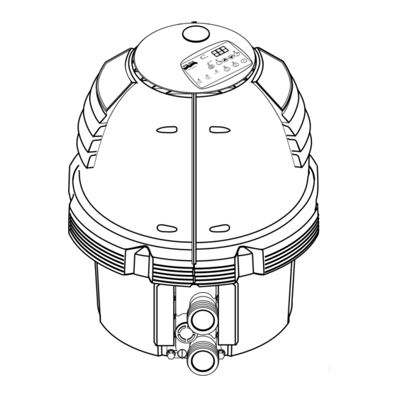
Page 4: Description Of The Heater
The heater may not be installed within five feet of the SEQUENCE OF OPERATION inside surface of a pool or spa unless it is separated by a An electronic temperature sensing thermistor in the mani- solid fence, wall or other permanent barrier. fold adapter inlet controls the heater operation. -
Page 5: What To Do If You Smell Gas
WHAT TO DO IF YOU SMELL GAS 3. Pregnant women beware! Soaking in water above 102°F (39°C) can cause fetal damage during the first • Do not try to light any appliance. three months of pregnancy (resulting in the birth of a •... -
Page 6: To Turn Off Gas To The Appliance
10. Set 3-way valves on inlet and outlet to pool or spa, as 6. Turn the knob on the gas control clockwise ( ) to appropriate. the black line, depress slightly, and turn to “OFF” posi- 11. Turn on all electric power to the appliance. tion. -
Page 7: After Start-Up
The five operating switches are: After start-up, the outlet water pipe should feel slightly warmer than the inlet pipe. If it feels hot, or if you hear the POOL ON Press this button to govern heater operation by water in the heater boiling, there may not be enough water the pool temperature setting. -
Page 8: Care/Maintenance/Winterizing
CARE AND MAINTENANCE Explosion hazard. Purging the system with compressed air can cause components to explode, with MAINTENANCE INSTRUCTIONS risk of severe injury or death to anyone nearby. Use only Risk of fire or explosion from flammable a low pressure (below 5 PSI or 35 kPa), high volume blow- vapors. -
Page 9: Installation Instructions
INSTALLATION INSTRUCTIONS HEATER CLEARANCES – OUTDOOR The heater must be installed with the top of the vent at Risk of fire, explosion, or asphyxiation if least 10 feet (3M) below, or to either side of, any opening heater is improperly installed, adjusted, serviced or main- into a building. -
Page 10: Outdoor Shelter/Indoor Installation
CONTROL PANEL INDEXING The heater is design certified by CSA International for installation on combustible flooring; in alcoves; basements; The exhaust discharges vertically from outside the vent in closet or utility rooms (in the U.S.) cover. The heater control panel assembly on top of the jacket can be turned to any of six positions for convenient INSTALLATION IN A GARAGE access to the panel as follows:... - Page 11 HEATER CLEARANCES – CSA B149.1, Natural Gas and Propane Installation Codes, as applicable, and any local codes that may apply. OUTDOOR SHELTER (Canada) or INDOOR (U.S.) The minimum net free area in square inches shall be The following clearances must be maintained from com- as follows: bustible surfaces: Table 2: Combustion and Ventilation...
- Page 12 When assembling a vent, chart below: pick one manufacturer and be sure that all vent parts come Metal Flue Collar Sta-Rite Part No. from that manufacturer and are specified by the manufac- turer for your system. Follow manufacturer’s instructions, 4x6”...
- Page 13 VENT TO THE HEATER FIGURE 12A: Typical Metal Vent Pipe Installation-Canada (Vertical – Negative Pressure) Metallic: 1. Order an Appliance Adapter kit: Sta-Rite Part No. 77707-0086 for Saf-T Vent ® or Saf-T Vent ® Sta-Rite Part No. 77707-0087 for Z-Vent.
- Page 14 from the heater at least 1/4” per foot (2cm/M). Install Table 4: Vent Termination Height vs. Listed condensate drains at low points where conden- Roof Pitch – U.S. sate might collect. Plumb condensate drains to a drain Minimum Height through hard piping or high-temperature tubing such Roof Pitch Above Roof* as silicone rubber or EPDM rubber –...
-
Page 15: Water Connections
Fire Hazard. Do not run the heater vent Max 12" into a common vent with any other appliance. Do not 4' Min. 4' Min. Min 3" Vent Vent run the Special Gas Vent into, through, or within any Termination Termination Vent 4' Min. - Page 16 A manual bypass valve should be installed across the 3-Way Chlorinator heater when the pump flow exceeds 120 GPM (454 LPM). Valve See instructions below for setting of the manual bypass. Make sure that the outlet plumbing from the heater con- Heater tains no shut-off valves or other flow restrictions that could prevent flow through the heater (except as noted below).
- Page 17 WATER FLOW RATE Do NOT sanitize the pool by putting chlorine tablets or sticks into the skimmer(s). When the pump is off, this will Maximum and minimum water flow rates required by the cause a high concentration of chlorine to enter the heater, heater are listed below: which could cause corrosion damage to the heat exchanger.
-
Page 18: Pressure Relief Valve
WATER PRESSURE SWITCH Pressure Switch is no longer adequate. A Flow Switch must be installed instead. Hazardous pressure. Do not bypass the Water NOTICE: Heater operation with incorrect Pressure Switch Pressure Switch or render it inoperable. setting may cause operation with no water flow. Operation Switch Settings of the heater without sufficient water flow may severely damage it. -
Page 19: Checking Combination Gas Control Valve
To avoid water damage or scalding from operation of the To High Side of Differential Pressure Gauge relief valve, install a drain pipe in the outlet of the pressure relief valve that will direct water discharging from the valve to a safe place for disposal. Do not install any reduc- Connection for ing couplings or valves in the drain pipe. -
Page 20: Gas Connections
GAS CONNECTIONS PRESSURE TESTING The heater requires a gas supply of not less than Before operating the heater, the heater and its gas connec- 4” (10.2cm) wc and not more than 14” (35.6cm) wc. tions must be leak tested. Test all gas connections for leaks Gas supply pressures outside of this range may result in with soapy water. - Page 21 Connect the L1 of the power supply to the black wire, the NOTICE: When using a timer and Fireman’s Switch, the L2 or neutral lead to the red wire, and the ground wire to heater’s power supply should come from the load side of the green wire (See Figure 23).
- Page 22 6. Reinstall and bolt up the jacket halves. The fuse for the Fireman’s Switch is a 1.25 amp 1-1/4x1/4” fast blow fuse, available locally. MAXIMUM TEMPERATURE SET POINT 1. Unbolt and remove upper jacket halves (see Figure 3, Page 5). 2.
- Page 23 Initial Troubleshooting Only qualified, trained service technicians with appropriate test equipment should service the heater. Remember that all parts of the system affect heater operation. Before starting this troubleshooting procedure, make sure that the pump is running correctly, that there are no blockages in the system, that the valves are correctly set and that the time clock is correctly set and is running.
- Page 24 Heater Will Not Fire - A Start Depress “POOL” or “SPA” ON Heater should fire on demand Is green “SPA” or button on Membrane Pad. for heat. “POOL” LED “on” Does “POOL” or “SPA” LED come on? Check that correct 12-pin Check for line voltage to Restore power to heater.
- Page 25 Heater Will Not Fire - B Start Increase POOL/SPA tempera- Is red “SERVICE Is red “SERVICE SYSTEM” ture setting on Membrane HEATER” LED “on” LED on? Pad above actual water tem- perature. Heater should fire on demand for heat. If not, Verify that pump is on, filter is and no other red LED’s light, not blocked, and the water...
-
Page 26: Troubleshooting
Heater Will Not Fire - C Start Is “SERVICE HEATER” LED Go to “INITIAL “on”? TROUBLESHOOTING” Turn off power to heater for 5 seconds, Continue to observe heater and turn back on. for several minutes. Cycle Make sure tempera- heater on and off several ture setting is above times. - Page 27 Heater Will Not Fire - D IMPORTANT! READ ME FIRST!! IMPORTANT! READ ME FIRST!! meter will read either 0 VAC or 240 VAC. If your ICM is If your heater is correctly connected to 240 Volts AC, The good, your meter will read some voltage between 0 and Ignition Control Module (ICM) will convert the 240VAC to 240 VAC.
-
Page 28: Diagnostic Led’s
Diagnostic LED’s: AGS, AFS, HLS, PS, THERMISTOR Verify that water flow rate is Service pump and filter to AGS or HLS “on” above minimum required for restore proper flow. After ser- heater. vicing, verify proper operation Replace High Limit of Pressure Switch (PS). Switch (HLS) or Automatic Gas Verify that inlet water temper-... -
Page 29: Sfs Diagnostic Led’s
(See Page 36) DONE Change Low Level Board Programming to “SF1” (See Check the J3 and J6 Page 4-11 in S5066, “Sta-Rite Reset power to Heater and connectors for corrosion Pool/Spa Heater Training and retry. Heater should fire. on the male pins. - Page 30 Burner Troubleshooting SYMPTOM CAUSE REMEDY Loud, high-pitched whine Flame is too rich. Verify pressure tap between gas valve and blower inlet. Turn to Page 19 and verify that the gas regulator setting is 0.2” (0.5cm) wc below the blower inlet pressure. Replace gas orifice with smaller size.
-
Page 31: Repair Parts
2737 0197 parts breakdown (Key Nos. 10 through 13), (Key Nos. 10 through 12), see Page 34 See Page 33 Repair Parts are available from your Sta-Rite dealer. If your dealer cannot supply you, call Sta-Rite Customer Service at 1-800-752-0183. - Page 32 For Heater mounting PI LO bolts and clamps, purchase separately Bolt Down Bracket Kit, Part No. 42001-0085S. 2692 1196 115/230...
- Page 33 REPAIR PARTS – BURNER SYSTEM Model SR400NA Part SR200NA SR333NA SR400LP Description Qty. SR200LP SR333LP SR400HD Combination Gas Control Valve Kit 42001-0051S 42001-0051S 42001-0051S 3/4” Union 38404-4097S 38404-4097S 38404-4097S • Gas Orifice Kit – NG (Incl. Key Nos. 3 and 4)† 77707-0331 77707-0321 77707-0311...
-
Page 34: Repair Parts – Water System
2691 1196 REPAIR PARTS – WATER SYSTEM Model SR400NA Part SR200NA SR333NA SR400LP Description Qty. SR200LP SR333LP SR400HD Tube Sheet Coil Assembly Kit (Includes Key No. 2) 77707-0232 77707-0233 77707-0234 SR400HD Tube Sheet Coil Assembly Kit (Includes Key No. 2) –... -
Page 35: Repair Parts – Electrical System
REPAIR PARTS – ELECTRICAL SYSTEM Model SR400NA Part SR200NA SR333NA SR400LP Description Qty. SR200LP SR333LP SR400HD • Display Cover Retainer Cap Kit (Incl. Key No. 1)* 77707-0009 77707-0009 77707-0009 Display Cover Retainer Cap 42001-0009 42001-0009 42001-0009 • CPSC Warning Label 32165-4084 32165-4084 32165-4084... -
Page 36: Wiring Diagrams/External Control Interface
Pool Heater Wiring Connection Diagram CONNECTION DIAGRAM If cable from AGS Switch Air Flow Switch Membrane Pad is a 6-Conductor Stack Flue Sensor Extra Switch 1 Cable, connect it Gas Valve Y/BL Hi-Limit Switch to pins 4 - 9 on Operating Control Pressure Switch Board as shown. - Page 37 Pool Heater Electrical Schematic Ladder Diagram LADDER DIAGRAM 120/240 NOTES: 24 VAC IGNITER AND TH ARE CONNECTED ON THE IGNITION MODULE. BLOWER 2. ) PIN AND SOCKET CONNECTOR. 3. ) IF ANY OF THE ORIGINAL WIRES AS SUPPLIED WITH THE APPLIANCE MUST BE REPLACED, 120/240 THEY MUST BE REPLACED WITH TYPE 105°C OR ITS EQUIVALENT.
-
Page 38: Warranty
• Complete a warranty registration at www.staritepool.com by clicking on “Register Products” and selecting Sta-Rite Pool OR • Complete bottom portion completely and mail within 10 days of installation to Sta-Rite, Attn.: Warranty Dept., 293 Wright St., Delavan , WI 53115 Warranty Registration Card ■...
Need help?
Do you have a question about the 200K BTU/HR and is the answer not in the manual?
Questions and answers