Table of Contents
Advertisement
Advertisement
Table of Contents

Related Manuals for Asus SABERTOOTH 990FX


Summary of Contents for Asus SABERTOOTH 990FX
- Page 1 SABERTOOTH 990FX...
- Page 2 Product warranty or service will not be extended if: (1) the product is repaired, modified or altered, unless such repair, modification of alteration is authorized in writing by ASUS; or (2) the serial number of the product is defaced or missing.
-
Page 3: Table Of Contents
Contents Notices ........................vii Safety information ....................viii About this guide ......................ix SABERTOOTH 990FX specifications summary ............xi Chapter 1: Product Introduction 1.1 Welcome! ....................1-1 1.2 Package contents..................1-1 1.3 Special features..................1-2 1.3.1 Product highlights................ 1-2 1.3.2 “Ultimate COOL!” Thermal Solution ..........1-3 1.3.3... - Page 4 Tools menu ....................3-28 3.9 Exit menu ....................3-30 3.10 Updating BIOS ..................3-31 3.10.1 ASUS Update utility..............3-31 3.10.2 ASUS EZ Flash 2 utility ............. 3-34 3.10.3 ASUS BIOS Updater ..............3-36 Chapter 4: Software support 4.1 Installing an operating system ..............4-1 4.2 Support DVD information ................4-1 4.2.1...
- Page 5 Contents 4.4.2 Installing Serial ATA hard disks ..........4-30 4.4.3 Setting the RAID item in BIOS ..........4-30 4.4.4 Option ROM Utility ............4-31 ® 4.5 Creating a RAID driver disk..............4-34 4.5.1 Creating a RAID driver disk without entering the OS ....4-34 4.5.2 Creating a RAID driver disk in Windows ........
-
Page 6: Notices
Complying with the REACH (Registration, Evaluation, Authorisation, and Restriction of Chemicals) regulatory framework, we published the chemical substances in our products at ASUS REACH website at http://csr.asus.com/english/REACH.htm. DO NOT throw the motherboard in municipal waste. This product has been designed to enable proper reuse of parts and recycling. -
Page 7: Safety Information
Safety information Electrical safety • To prevent electrical shock hazard, disconnect the power cable from the electrical outlet before relocating the system. • When adding or removing devices to or from the system, ensure that the power cables for the devices are unplugged before the signal cables are connected. If possible, disconnect all power cables from the existing system before you add a device. -
Page 8: About This Guide
Refer to the following sources for additional information and for product and software updates. ASUS websites The ASUS website provides updated information on ASUS hardware and software products. Refer to the ASUS contact information. Optional documentation Your product package may include optional documentation, such as warranty flyers, that may have been added by your dealer. - Page 9 Conventions used in this guide To ensure that you perform certain tasks properly, take note of the following symbols used throughout this manual. DANGER/WARNING: Information to prevent injury to yourself when trying to complete a task. CAUTION: Information to prevent damage to the components when trying to complete a task.
-
Page 10: Sabertooth 990Fx Specifications Summary
*4 x DIMM, Max. 32GB, DDR3 1866/1600/1333/1066 MHz, ECC, Non- ECC and un-buffered memory Dual channel memory architecture * Refer to www.asus.com or user manual for the Memory QVL (Qualified Vendors Lists) of AM3+ / AM3 CPU ** Due to OS limitation, when installing total memory of 4GB capacity... - Page 11 “Safe & Stable!” Guardian Angel - ESD Guards - MemOK! - Anti Surge Other Special Features Front Panel USB 3.0 Support ASUS UEFI BIOS EZ Mode featuring friendly graphics user interface AI Suite II ASUS Q-Connector ASUS Q-Shield ASUS Q-LED (CPU, DRAM, VGA, Boot Device LED)
- Page 12 SABERTOOTH 990FX specifications summary Manageability WfM 2.0, DMI 2.0, WOL by PME, WOR by PME, PXE Back Panel I/O Ports 1 x PS/2 Keyboard/Mouse combo port 1 x Optical S/PDIF Output port 1 x Power eSATA 3Gb/s port (green) 1 x eSATA 3Gb/s port (red)
-
Page 13: Welcome
® The motherboard delivers a host of new features and latest technologies, making it another standout in the long line of ASUS quality motherboards! Before you start installing the motherboard, and hardware devices on it, check the items in your package with the list below. -
Page 14: Special Features
Complete USB 3.0 Solution Double USB access, double convenience ASUS facilitates strategic USB 3.0 accessibility for both the front and rear panel - 4 USB 3.0 ports in total. Experience the latest plug & play connectivity at speeds up to 10 times faster than USB 2.0. The SABERTOOTH 990FX affords greater convenience to high speed connectivity. -
Page 15: Ultimate Cool!" Thermal Solution
“TUF ENGINE!” Power Design DIGI+ VRM Herald the Arrival of a New Digital Power Design Era The new ASUS DIGI+ VRM design upgrades motherboard power delivery to a digital standard. The 8+2 digital architecture provides the highest power efficiency, generating less heat to enhance longer component lifespan and ensure minimal powerloss. With ASUS DIGI+ VRM, users can easily adjust power phase performance, enabling new PWM voltage and frequency modulation controls. -
Page 16: Asus Diy
AI Suite II One-stop Access to Innovative ASUS Features With its user-friendly interface, ASUS AI Suite II consolidates all the exclusive ASUS features into one simple to use software package. It allows you to supervise energy management, fan speed control, voltage and sensor readings. This all-in-one software offers diverse and ease to use functions, with no need to switch back and forth between different utilities. - Page 17 MyLogo2 Personalize your system with customizable boot logo The ASUS MyLogo 2 is the new feature present in the motherboard that allows you to personalize and add style to your system with customizable and animated boot logos. ASUS SABERTOOTH 990FX...
- Page 18 The motherboard is European Union’s Energy-related Products (ErP) ready, and ErP requires products to meet certain energy efficiency requirements in regards to energy consumptions. This is in line with ASUS vision of creating environment-friendly and energy-efficient products through product design and innovation to reduce carbon footprint of the product and thus mitigate environmental impacts.
-
Page 19: Before You Proceed
Before you install or remove any component, ensure that the ATX power supply is switched off or the power cord is detached from the power supply. Failure to do so may cause severe damage to the motherboard, peripherals, or components. ASUS SABERTOOTH 990FX... -
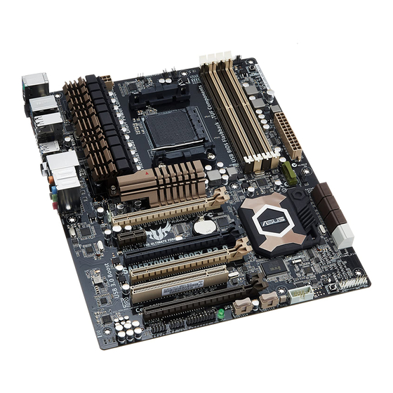
Page 20: Motherboard Overview
Motherboard overview 2.2.1 Motherboard layout Refer to 2.2.8 Internal connectors and 2.3.10 Rear panel connection for more information about rear panel connectors and internal connectors. Chapter 2: Hardware information... - Page 21 2-13 USB 2.0 connectors (10-1 pin USB1112, USB1314) 2-18 Standby power LED (SB_PWR) 2-15 IEEE 1394a port connector (10-1 pin IE1394_2) 2-19 Front panel audio connector (10-1 pin AAFP) 2-21 Digital audio connector (4-1 pin SPDIF_OUT) 2-19 ASUS SABERTOOTH 990FX...
-
Page 22: Central Processing Unit (Cpu)
2.2.2 Central Processing Unit (CPU) The motherboard comes with an AM3+ socket designed for AMD FX Series CPU up to 8-core, ® also compatible with AMD socket AM3 for AMD Phenom™ II/Athlon™ II/ Sempron™ 100 ® ® Series Processors. Ensure that all power cables are unplugged before installing the CPU. The AM3+ socket has a different pinout designe, ensure that you use a CPU designed for the AM3+/AM3 socket. -
Page 23: System Memory
The motherboard comes with four Double Data Rate 3 (DDR3) Dual Inline Memory Modules (DIMM) slots. A DDR3 module is notched differently from a DDR or DDR2 module. DO NOT install a DDR or DDR2 memory module to the DDR3 slot. Recommended memory configurations ASUS SABERTOOTH 990FX... -
Page 24: Memory Configurations
Memory configurations You may install 1GB, 2GB and 4GB unbuffered and non-ECC DDR3 DIMMs into the DIMM sockets. • You may install varying memory sizes in Channel A and Channel B. The system maps the total size of the lower-sized channel for the dual-channel configuration. Any excess memory from the higher-sized channel is then mapped for single-channel operation. - Page 25 SABERTOOTH 990FX Motherboard Qualified Vendors Lists (QVL) AM3 DDR3 1066 MHz capability Vendors Part No. Size Chip Brand Chip NO. Timing Voltage DIMM socket support (Optional) 1 DIMM 2 DIMM 4 DIMM Crucial CT12864BA1067.8FF MICRON D9KPT • • • Crucial CT12864BA1067.8SFD MICRON D9JNL • • • Crucial CT12872BA1067.9FF MICRON D9KPT(ECC) • •...
- Page 26 SABERTOOTH 990FX Motherboard Qualified Vendors Lists (QVL) AM3 DDR3 1333 MHz capability Vendors Part No. Size SS/DS Chip Brand Chip NO. Timing Voltage DIMM socket support (Optional) 1 DIMM 2 DIMM 4 DIMM A-DATA SU3U1333W8G9-B Elpida J4208BASE-DJ-F • • • Apacer 78.01GC6.9L0 Apacer AM5D5808DEJSBG • • • Apacer 78.A1GC6.9L1 Apacer AM5D5808FEQSBG •...
- Page 27 SABERTOOTH 990FX Motherboard Qualified Vendors Lists (QVL) AM3 DDR3 1333 MHz capability Vendors Part No. Size SS/DS Chip Brand Chip NO. Timing Voltage DIMM socket support (Optional) 1 DIMM 2 DIMM 4 DIMM OCZ3RPR1333C9LV8GK 9-9-9 1.65 • • ( 2x 4GB ) PC310600U-9-10-A0 A3P1GF3FGF • • • AL8F8G73D-DG1 A3P1GF3DGF • • •...
- Page 28 SABERTOOTH 990FX Motherboard Qualified Vendors Lists (QVL) AM3 DDR3 1600 MHz capability Vendors Part No. Size Chip Brand Chip NO. Timing Voltage DIMM socket support (Optional) 1 DIMM 2 DIMM 4 DIMM CORSAIR HX3X12G1600C9(XMP) 12GB DS - 9-9-9-24 • • • ( 6x 2GB ) CORSAIR CMZ16GX3M4A1600C9(XMP) 16GB DS - 9-9-9-24 •...
- Page 29 SABERTOOTH 990FX Motherboard Qualified Vendors Lists (QVL) AM3 DDR3 1600 MHz capability Vendors Part No. Size Chip Brand Chip NO. Timing Voltage DIMM socket support (Optional) 1 DIMM 2 DIMM 4 DIMM KINGSTON KHX1600C9D3K2/4GX(XMP) DS - 1.65 • • • ( 2x 2GB ) KINGSTON KHX1600C9D3K2/4GX(XMP) DS - 1.65 • • •...
- Page 30 SABERTOOTH 990FX Motherboard Qualified Vendors Lists (QVL) AM3 DDR3 1800 MHz capability Vendors Part No. Size Chip Brand Chip NO. Timing Voltage DIMM socket support (Optional) 1 DIMM 2 DIMM 4 DIMM G.SKILL F3-14400CL6D-4GBFLS(XMP) 4GB (2 x 2GB) DS - 6-8-6-24 1.65 • • • G.SKILL F3-14400CL9D-4GBRL(XMP) 4GB (2 x 2GB) DS - 9-9-9-24 •...
- Page 31 SABERTOOTH 990FX Motherboard Qualified Vendors Lists (QVL) AM3 DDR3 2000 MHz capability Vendors Part No. Size Chip Brand Chip NO. Timing Voltage DIMM socket support (Optional) DIMM DIMM DIMM A-DATA AX3U2000GB2G9B(XMP) DS - 9-11-9-27 1.55~1.75 • A-DATA AX3U2000GC4G9B(XMP) DS - 9-11-9-27 1.55~1.75 • Apacer 78.AAGD5.9KD(XMP) DS - 9-9-9-27 •...
- Page 32 SABERTOOTH 990FX Motherboard Qualified Vendors Lists (QVL) AM3+ DDR3 2000 MHz capability Vendors Part No. Size Chip Brand Chip NO. Timing Voltage DIMM socket support (Optional) 1 DIMM 2 DIMM 4 DIMM A-DATA AX3U2000GB2G9B(XMP) DS - 9-11-9-27 1.55~1.75 • • A-DATA AX3U2000GC4G9B(XMP) DS - 9-11-9-27 1.55~1.75 • • Apacer 78.AAGD5.9KD(XMP) 6GB(3 x 2GB)
-
Page 33: Expansion Slots
Slot No. Slot Description PCIe 2.0 x16_1 slot (single a t x16, dual at x16/x16, triple at x16/x8/x8 mode) PCIe 2.0 x1_1 slot PCIe 2.0 x16_2 slot PCIe 2.0 x16_3 slot PCI slot 1 PCIe 2.0 x16_4 slot ASUS SABERTOOTH 990FX 2-15... - Page 34 PCI Express operating mode VGA configuration PCIe 2.0 x16_1 PCIe 2.0x16_2 PCIe 2.0x16_3 PCIe 2.0x16_4 Single VGA/PCIe card (Recommend for single VGA) Dual VGA/PCIe card 3-way SLI • In single VGA card mode, use the PCIe 2.0 x16_1 slot (beige) for a PCI Express x16 graphics card to get better performance. • In CrossFireX™ or SLI™ mode, use the PCIe 2.0 x16_1 and PCIe 2.0 x16_3 slots for PCI Express x16 graphics cards to get better performance.
- Page 35 PCIEX16_2 – – – – shared – – – PCIEX16_3 – – – shared – – – – PCIEX16_4 shared – – – – – – – PCIEX1_1 shared – – – – – – – ASUS SABERTOOTH 990FX 2-17...
-
Page 36: Jumper
2.2.5 Jumper Clear RTC RAM (3-pin CLRTC) This jumper allows you to clear the Real Time Clock (RTC) RAM in CMOS. You can clear the CMOS memory of date, time, and system setup parameters by erasing the CMOS RTC RAM data. The onboard button cell battery powers the RAM data in CMOS, which include system setup information such as system passwords. -
Page 37: Onboard Switch
BIOS default settings. A messgae will appear during POST reminding you that the BIOS has been restored to its default settings. • We recommend that you download and update to the latest BIOS version from the ASUS website at www.asus.com after using the MemOK! function. ASUS SABERTOOTH 990FX 2-19... -
Page 38: Onboard Leds
2.2.7 Onboard LEDs Standby Power LED The motherboard comes with a standby power LED. The green LED lights up to indicate that the system is ON, in sleep mode, or in soft-off mode. This is a reminder that you should shut down the system and unplug the power cable before removing or plugging in any motherboard component. -
Page 39: Internal Connectors
® XP Service Pack 3 or later versions before using Serial ATA hard disk drives. The Serial ATA RAID feature is available only if you are using Windows ® XP Service Pack 3 or later versions. ASUS SABERTOOTH 990FX 2-21... - Page 40 JMicron JMB362 Serial ATA 3.0 Gb/s connectors (7-pin SATA3G_E1/E2 [black]) ® These connectors connect to Serial ATA 3.0 Gb/s hard disk drives and optical disc drives via Serial ATA 3.0 Gb/s signal cables. Serial port connector (10-1 pin COM1) This connector is for a serial (COM) port. Connect the serial port module cable to this connector, then install the module to a slot opening at the back of the system chassis.
- Page 41 Never connect a 1394 cable to the USB connectors. Doing so will damage the motherboard! You can connect the front panel USB cable to the ASUS Q-Connector (USB, blue) first, and then install the Q-Connector (USB) to the USB connector onboard if your chassis supports front panel USB ports.
- Page 42 IEEE 1394a port connector (10-1 pin IE1394_2) This connector is for an IEEE 1394a port. Connect the IEEE 1394a module cable to this connector, then install the module to a slot opening at the back of the system chassis. Never connect a USB cable to the IEEE 1394a connector. Doing so will damage the motherboard! The IEEE 1394a module is purchased separately.
- Page 43 The CPU_FAN connector supports the CPU fan of maximum 1A (12 W) fan power. • If you install two VGA cards, we recommend that you plug the rear chassis fan cable to the motherboard connector labeled CHA_FAN1 or CHA_FAN2 for better thermal environment. ASUS SABERTOOTH 990FX 2-25...
-
Page 44: Front Panel Audio Connector
Front panel audio connector (10-1 pin AAFP) This connector is for a chassis-mounted front panel audio I/O module that supports either HD Audio or legacy AC`97 audio standard. Connect one end of the front panel audio I/O module cable to this connector. • We recommend that you connect a high-definition front panel audio module to this connector to avail of the motherboard’s high-definition audio capability. - Page 45 1000W power or above to ensure the system stability. • If you are uncertain about the minimum power supply requirement for your system, refer to the Recommended Power Supply Wattage Calculator at http://support.asus. com/PowerSupplyCalculator/PSCalculator.aspx?SLanguage=en-us for details. ASUS SABERTOOTH 990FX 2-27...
-
Page 46: System Panel Connector
11. System panel connector (20-8 pin PANEL) This connector supports several chassis-mounted functions. • System power LED (2-pin PLED) This 2-pin connector is for the system power LED. Connect the chassis power LED cable to this connector. The system power LED lights up when you turn on the system power, and blinks when the system is in sleep mode. -
Page 47: Building Your Computer System
Building your computer system 2.3.1 Additional tools and components to build a PC system 1 bag of screws Philips (cross) screwdriver PC chassis Power supply unit AMD AM3+ CPU AMD AM3+ compatible CPU Fan DIMM SATA hard disk drive SATA optical disc drive (optional) Graphics card (optional) The tools and components in the table above are not included in the motherboard package. ASUS SABERTOOTH 990FX 2-29... -
Page 48: Cpu Installation
2.3.2 CPU installation The AMD AM3+ socket is compatible with AMD AM3+ and AM3 processors. Ensure you use a CPU designed for the AM3+ socket. The CPU fits in only one correct orientation. DO NOT force the CPU into the socket to prevent bending the connectors on the socket and damaging the CPU! 2-30 Chapter 2: Hardware information... -
Page 49: Cpu Heatsink And Fan Assembly Installation
2.3.3 CPU heatsink and fan assembly installation Apply the Thermal Interface Material to the CPU heatsink and CPU before you install the heatsink and fan if necessary. ASUS SABERTOOTH 990FX 2-31... - Page 50 To install the CPU heatsink and fan assembly 2-32 Chapter 2: Hardware information...
- Page 51 ASUS SABERTOOTH 990FX 2-33...
-
Page 52: Motherboard Installation
2.3.5 Motherboard installation The diagrams in this section are for reference only. The motherboard layout may vary with models, but the installation steps remain the same. 2-34 Chapter 2: Hardware information... - Page 53 DO NOT overtighten the screws! Doing so can damage the motherboard. ASUS SABERTOOTH 990FX 2-35...
-
Page 54: Atx Power Connection
2.3.6 ATX Power connection 2-36 Chapter 2: Hardware information... -
Page 55: Sata Device Connection
2.3.7 SATA device connection ASUS SABERTOOTH 990FX 2-37... -
Page 56: Front I/O Connector
2.3.8 Front I/O Connector To install ASUS Q-Connector To install USB 2.0 Connector To install front panel audio connector AAFP USB 2.0 To install USB 3.0 Connector USB 3.0 2-38 Chapter 2: Hardware information... -
Page 57: Expension Card Installation
2.3.9 Expension Card installation To install PCIe x16 cards To install PCIe x1 cards To install PCI cards ASUS SABERTOOTH 990FX 2-39... -
Page 58: Rear Panel Connection
2.3.10 Rear panel connection Rear panel connectors 1. PS/2 keyboard/mouse combo port 8. Optical S/PDIF Out port 2. USB 2.0 ports 5 and 6 9. Power External SATA port 3. USB 3.0 ports 1 and 2 10. IEEE 1394a port 4. USB 2.0 ports 3 and 4 11. -
Page 59: Audio I/O Connections
Pink Mic In Mic In Mic In Mic In Orange – – Center/Subwoofer Center/Subwoofer Black – Rear Speaker Out Rear Speaker Out Rear Speaker Out Gray – – – Side Speaker Out 2.3.11 Audio I/O connections Audio I/O ports Connect to Headphone and Mic ASUS SABERTOOTH 990FX 2-41... - Page 60 Connect to Stereo Speakers Connect to 2.1 channel Speakers Connect to 4.1 channel Speakers 2-42 Chapter 2: Hardware information...
- Page 61 Connect to 5.1 channel Speakers Connect to 7.1 channel Speakers ASUS SABERTOOTH 990FX 2-43...
-
Page 62: Starting Up For The First Time
Starting up for the first time After making all the connections, replace the system case cover. Be sure that all switches are off. Connect the power cord to the power connector at the back of the system chassis. Connect the power cord to a power outlet that is equipped with a surge protector. Turn on the devices in the following order: Monitor External SCSI devices (starting with the last device on the chain) -
Page 63: Chapter 3: Bios Setup
BIOS setup Knowing BIOS The new ASUS UEFI BIOS is an Extensible Firmware Interface that complies with uEFI architecture, offering a user-friendly interface that goes beyond traditional keyboard-only BIOS controls to enable more flexible and convenient mouse input. Users can easily navigate the new UEFI BIOS with the same smoothness as their operating system. -
Page 64: Ez Mode
Boot Menu(F8) Default(F5) Loads optimized default Selects the boot device priority Power Saving mode Normal mode ASUS Optimal mode Displays the system properties of the selected mode on the right hand side Selects the boot device priority • The boot device options vary depending on the devices you installed to the system. The Boot Menu(F8) button is available only when the boot device is installed to the •... -
Page 65: Advanced Mode
The Advanced Mode provides advanced options for experienced end-users to configure the BIOS settings. The figure below shows an example of the Advanced Mode. Refer to the following sections for the detailed configurations. To access the EZ Mode, click Exit, then select ASUS EZ Mode. Back button Menu items... -
Page 66: Configuration Fields
Menu items The highlighted item on the menu bar displays the specific items for that menu. For example, selecting Main shows the Main menu items. The other items (Ai Tweaker, Advanced, Monitor, Boot, Tool, and Exit) on the menu bar have their respective menu items. -
Page 67: Main Menu
RAM to clear the BIOS password. See section 2.2.5 Jumper for information on how to erase the RTC RAM. The Administrator or User Password items on top of the screen show the default • Not Installed. After you set a password, these items show Installed. ASUS SABERTOOTH 990FX... -
Page 68: Administrator/User Passwords
Administrator Password If you have set an administrator password, we recommend that you enter the administrator password for accessing the system. Otherwise, you might be able to see or change only selected fields in the BIOS setup program. To set an administrator password: Select the Administrator Password item and press <Enter>. -
Page 69: Ai Tweaker Menu
VRM Spread Spectrum Disabled F2: Previous Values F5: Optimized Defaults CPU Power Duty Control T. Probe Th... F10: Save ESC: Exit CPU & NB Voltage Offset Mode Offset Mode Sign Version 2.00.1201. Copyright (C) 2010 American Megatrends, Inc. ASUS SABERTOOTH 990FX... - Page 70 Scroll down to display the following items: VDDR CPU & NB Voltage Offset Mode Min = 1.20V Max = 1.80V Offset Mode Sign Standard = 1.20V Oncrement = 0.0050V CPU Offset Voltage 1.356V Auto +/- : Raise/Reduce CPU/NB Offset Mode Sign 1.224V CPU/NB Offset Voltage 1.100V...
- Page 71 <-> keys to adjust the value. To restore the default setting, type [auto] using the keyboard and press the <Enter> key. Changing the values in this menu may cause the system to become unstable! If this happens, revert to the default settings. ASUS SABERTOOTH 990FX...
- Page 72 DRAM Driving Control DCT0 Information: CKE drive strength [1.5x] Configuration options: [Auto] [1x] [1.25x] [1.5x] [2x] CS/ODT drive strength [1.5x] Configuration options: [Auto] [1x] [1.25x] [1.5x] [2x] ADDR/CMD drive strength [1.5x] Configuration options: [Auto] [1x] [1.25x] [1.5x] [2x] MEMCLK drive strength [1.5x] Configuration options: [Auto] [0.75x] [1x] [1.25x] [1.5x] Data drive strength [1x] Configuration options: [Auto] [0.75x] [1x] [1.25x] [1.5x] DQS drive strength [1x]...
- Page 73 Reducing phase number under light system loading to increase VRM efficiency [Standard] Proceeds phase control depending on the CPU loading. [Optimized] Loads the ASUS optimized phase tuning profile. [Extreme] Proceeds the full phase mode. [Manual Adjustment] Allows manual adjustment.
- Page 74 VRM Spread Spectrum [Disabled] This item appears only when you set the CPU Voltage Frequency item to [Auto] and allows you to enable the spread spectrum to enhance system stability. VRM Fixed Frequency Mode [300] This item appears only when you set the CPU Voltage Frequency item to [Manual] and allows you to set a fixed VRM frequency.
- Page 75 Allows you to set the VDD PCIE voltage. The values range from 1.10V to 2.20V with a 0.005V interval. The text color in the configuration field indicates voltage condition. VDDR [Auto] Allows you to set the VDDR voltage. The values range from 1.20V to 1.80V with a 0.0050V interval. ASUS SABERTOOTH 990FX 3-13...
-
Page 76: Advanced Menu
Advanced menu The Advanced menu items allow you to change the settings for the CPU and other system devices. At the bottom right corner of the menu are the navigation keys for the BIOS setup program. Use the navigation keys to select items in the menu and change the settings. Use <F12> key to capture the BIOS screen and save it to the removable storage device. -
Page 77: Cpu Configuration
Enables AMD virtualization in CPU. This secure virtual mode will let you run multiple operation system on the same physical hardware by decoupling operation system and physical hardware with the hypervisor layer. [Disabled] Disables this function. ASUS SABERTOOTH 990FX 3-15... -
Page 78: North Bridge Configuration
3.5.2 North Bridge Configuration UEFI BIOS Utility - Advanced Mode Exit Main Ai Tweaker Advanced Monitor Boot Tool Back Advanced\ North Bridge > North Bridge Configuration IOMMU is support on Linux based systems to convert 32bit I/O to 64bit IOMMU Mode Disabled MMIO. -
Page 79: Sata Configuration
AHCI (Advabced Host Controller Interface). The AHCI allows the onboard storage driver to enable advanced Serial ATA features that increases storage performance on random workloads by allowing the drive to internally optimize the order of commands. ASUS SABERTOOTH 990FX 3-17... - Page 80 SATA Port5-Port6 [AHCI] Allows you to set the SATA configuration. This item appears only when you set the OnChip SATA Channel item to [Enabled]. [IDE] Set to [IDE] when you want to use the Serial ATA hard disk drives as Parallel ATA physical storage devices. [AHCI] Set to [AHCI] when you want the SATA hard disk drives to use the AHCI (Advabced Host Controller Interface).
-
Page 81: Usb Configuration
USB support is disabled. Legacy USB3.0 Support [Enabled] [Enabled] Enables the support for USB 3.0 devices on legacy operating systems (OS). [Disabled] Disables the function. EHCI Hand-off [Disabled] [Disabled] Disables the function. [Enabled] Enables the support for operating systems without an EHCI hand-off feature. ASUS SABERTOOTH 990FX 3-19... -
Page 82: Cpu Core On/Off Fuction
Auto System might become unstable due to different CPU margins. ASUS Core Unlocker [Disabled] Allows you to enable ASUS Core Unlocker to get full computing power of processor. Configuration options: [Disabled] [Enabled] System might become unstable due to different CPU margins. CPU Core Activation [Auto] Allows you to manually turn off the second or the third core. -
Page 83: Onboard Devices Configuration
Configuration options: [Enabled] [Disabled] Display OptionRom in POST [Enabled] This item appears only when you set the JMB Storage OPROM item to [Enabled] and allows you to display or hide the OptionRom of the JMB storage controller during POST. Configuration options: [Enabled] [Disabled] ASUS SABERTOOTH 990FX 3-21... - Page 84 Asmedia USB 3.0 Controller [Enabled] [Enabled] Enables the USB 3.0 controller. [Disabled] Disables the controller. Asmedia USB 3.0 Battery Charging Support [Disabled] [Enabled] Enables the USB 3.0 battery charging support. [Disabled] Disables the fuction. Realtek LAN Controller [Enabled] [Enabled] Enables the Realtek LAN controller. [Disabled] Disables the controller. Realtek PXE OPROM [Disabled] This item appears only when you set the previous item to [Enabled] and allows you to enable or disable the PXE OptionRom of the Intel LAN controller.
-
Page 85: Apm
PME options will be switched off. ErP Ready [Enabled] Allows BIOS to switch off some power at S5 to get the system ready for ErP requirement. When set to [Enabled], all other PME options will be swtched off. Configuration options: [Disabled] [Enabled] ASUS SABERTOOTH 990FX 3-23... -
Page 86: Monitor Menu
Monitor menu The Monitor menu displays the system temperature/power status, and allows you to change the fan settings. UEFI BIOS Utility - Advanced Mode Exit Ai Tweaker Main Advanced Monitor Boot Tool CPU Temperature CPU Temperature +61ºC / +143ºF +61ºC / +143ºF MB Temperature +37ºC / +98ºF VCORE Voltage... - Page 87 The values range from 0% to 100%. When the CPU temperature is under 40ºC, the CPU fan will operate at the minimum When the CPU temperature is under 40ºC, the CPU fan will operate at the minimum duty cycle. ASUS SABERTOOTH 990FX 3-25...
- Page 88 CPU Fan Speed Low Limit [600 RPM] This item appears only when you enable the CPU Q-Fan Control feature and allows you to disable or set the CPU fan warning speed. Configuration options: [Ignore] [100RPM] [200 RPM] [300 RPM] [400 RPM] [500 RPM] [600 RPM] Chassis Q-Fan Control [Disabled] [Disabled] Disables the Chassis Q-Fan control feature.
-
Page 89: Boot Menu
Enables the full screen logo display feature. [Disabled] Disables the full screen logo display feature. Set this item to [Enabled] to use the ASUS MyLogo 2™ feature. Wait for ‘F1’ If Error [Enabled] When set to [Enabled], the system waits for the <F1> key to be pressed when error occurs. -
Page 90: Tools Menu
> ASUS SPD Information > ASUS O.C. Profile ASUS EZ Flash 2 Allows you to run ASUS EZ Flash 2. When you press <Enter>, a confirmation message appears. Use the left/right arrow key to select between [Yes] or [No], then press <Enter> to confirm your choice. - Page 91 Exit Main Ai Tweaker Advanced Monitor Boot Tool Back Tool\ ASUS O.C. Profile > O.C. Profile Configuration Save BIOS settings to Profile ========================================================== Setup Profile1 Status : Not Installed Setup Profile2 Status : Not Installed Setup Profile3 Status : Not Installed...
-
Page 92: Exit Menu
Exit Load Optimized Defaults Save Changes & Reset Discard Changes & Exit ASUS EZ Mode Launch EFI Shell from filesystem device Load Optimized Defaults This option allows you to load the default values for each of the parameters on the Setup menus. When you select this option or if you press <F5>, a confirmation window appears. -
Page 93: Updating Bios
BIOS in the future. Copy the original motherboard BIOS using the ASUS Update or BIOS Updater utilities. 3.10.1 ASUS Update utility The ASUS Update is a utility that allows you to manage, save, and update the motherboard BIOS in Windows environment. The ASUS Update utility allows you to: ®... - Page 94 To update the BIOS through the Internet: From the ASUS Update screen, select Update BIOS from Internet, and then click Next. Select the ASUS FTP site nearest you to avoid network traffic. If you want to enable the BIOS downgradable function and auto BIOS backup function, check the checkboxs before the two items on the screen.
- Page 95 The screenshots in this section are for reference only. The actual BIOS information vary by models. • Refer to the software manual in the support DVD or visit the ASUS website at www.asus.com for detailed software configuration. ASUS SABERTOOTH 990FX...
-
Page 96: Asus Ez Flash 2 Utility
3.10.2 ASUS EZ Flash 2 utility The ASUS EZ Flash 2 feature allows you to update the BIOS without having to use a bootable floppy disk or an OS-based utility. Before you start using this utility, download the latest BIOS from the ASUS website at www.asus.com. - Page 97 DO NOT shut down or reset the system while updating the BIOS to prevent system boot failure! Ensure to load the BIOS default settings to ensure system compatibility and stability. Select the Load Optimized Defaults item under the Exit menu. See section 3.9 Exit Menu for details. ASUS SABERTOOTH 990FX 3-35...
-
Page 98: Asus Bios Updater
3.10.3 ASUS BIOS Updater The ASUS BIOS Updater allows you to update BIOS in DOS environment. This utility also allows you to copy the current BIOS file that you can use as a backup when the BIOS fails or gets corrupted during the updating process. - Page 99 ASUSTek BIOS Updater for DOS V1.18 [2010/04/29] Current ROM Update ROM BOARD: SABERTOOTH 990FX BOARD: Unknown VER: 0401 VER: Unknown DATE: 04/26/2011 DATE: Unknown PATH: BIOS backup is done! Press any key to continue. Note Saving BIOS: ASUS SABERTOOTH 990FX 3-37...
- Page 100 At the FreeDOS prompt, type bupdater /pc /g and press <Enter>. D:\>bupdater /pc /g The BIOS Updater screen appears as below. ASUSTek BIOS Updater for DOS V1.18 [2010/04/29] Current ROM Update ROM BOARD: Unknown BOARD: SABERTOOTH 990FX VER: Unknown VER: 0401 DATE: 04/26/2010 DATE: Unknown PATH: SABER990FX.ROM...
-
Page 101: Chapter 4: Software Support
The support DVD that comes with the motherboard package contains the drivers, software applications, and utilities that you can install to avail all motherboard features. The contents of the support DVD are subject to change at any time without notice. Visit the ASUS website at www.asus.com for updates. 4.2.1 Running the support DVD Place the support DVD into the optical drive. -
Page 102: Obtaining The Software Manuals
The software manual files are in Portable Document Format (PDF). Install the Adobe ® Acrobat Reader from the Utilities menu before opening the files. ® Click the Manual tab. Click ASUS Motherboard Utility Guide from the manual list on the left. The Manual folder of the support DVD appears. Double-click the folder of your selected software. -
Page 103: Software Information
View the online help or readme file that came with the software application for more information. 4.3.1 AI Suite II AI Suite II is an all-in-one interface that integrates several ASUS utilities and allows users to launch and operate these utilities simultaneously. Installing AI Suite II To install AI Suite II on your computer Place the support DVD to the optical drive. - Page 104 Other feature buttons • Click to minimize the main menu bar as a tab on the side of the Windows desktop. Click the tab again to restore the main menu bar. Click to minimize the main menu bar as a tab Desktop • When on a function screen, click on the upper-right corner of the screen to switch back to the main menu bar.
- Page 105 AI Suite II icon in the Windows notification area ( ). AI Suite II is still running. • To exit AI Suite II, right click the AI Suite II icon in the Windows notification area, then, left-click and select Exit. ASUS SABERTOOTH 990FX...
- Page 106 Customizing the interface From the main menu bar, click Settings to customize the main menu bar settings and the interface’s skin. Application Allows you to select the application that you want to enable. Click Ok to restart AI Suite II and Tick the item that you want to display on the main menu bar, and apply the setting.
- Page 107 Allows you to modify the bar setting. Tick Auto hide and select the Click Apply to apply the setting. countdown time that the Auto hide function takes effect. The Auto hide function only takes effect in Bar mode. ASUS SABERTOOTH 990FX...
-
Page 108: Asus Thermal Radar
4.3.2 ASUS Thermal Radar The Thermal Radar monitors temps in critical parts of the motherboard in real time, automatically adjusting fan speeds to make sure the system maintains high stability without overheating. It consists of multiple sensors for various components on the motherboard, giving user the ability to monitor each one individually. - Page 109 Read the introduction and notice of the selected fan. Click Setting. Select a fan profile in the Profile Name drop-down list and click Apply. You can also configure other system fans by clicking the CHA and ASST icon below. ASUS SABERTOOTH 990FX...
- Page 110 Configuring user-customizable fan settings You can customize the fan speed to meet different computing and environment needs. To fast customize the fan speed Select User in the Profile Name drop- down list. Drag the control points on the fan speed curve to set the fan speed percentage.
- Page 111 If you are not sure how to choose the proper components to monitor and the percentage to adjust, click Auto and have Thermal Radar do the recommended settings for you. Click Apply for the setting to take effect. ASUS SABERTOOTH 990FX 4-11...
-
Page 112: Tool
After installing AI Suite II from the motherboard support DVD, launch TurboV EVO by clicking Tool > TurboV EVO on the AI Suite II main menu bar. Refer to the software manual in the support DVD or visit the ASUS website at www.asus.com for detailed software configuration. - Page 113 Set the CPU Ratio Setting item in BIOS to [Auto] before using the CPU Ratio function in TurboV. Refer to Chapter 3 of your motherboard user manual for details. • The CPU Ratio bars show the status of the CPU cores, which vary with your CPU model. ASUS SABERTOOTH 990FX 4-13...
- Page 114 DIGI+ VRM ASUS DIGI+ VRM allows you to adjust VRM voltage and frequency modulation to enhance reliability and stability. It also provides the highest power efficiency, generating less heat to longer component lifespan and minimize power loss. After installing AI Suite II from the motherboard support DVD, launch DIGI+ VRM by clicking Tool > DIGI+ VRM on the AI Suite II main menu bar.
- Page 115 Medium: 25% • High: 50% • Ultra: 75% • Extreme: 100% • The actual performance boost may vary depending on your CPU specification. • Do not remove the thermal module. The thermal conditions should be monitored. ASUS SABERTOOTH 990FX 4-15...
- Page 116 Reduce phase number under light system loading to increase VRM efficiency. • Standard: Phase control based on CPU command. • Optimized: ASUS optimized phase tuning profile • Extreme: Full phase mode • Manual Adjustment: Phase number adjusted by current (A) step •...
- Page 117 Click the Voltage/Temperature/Fan Speed tabs and select the sensors that you want to monitor. The History Record tab allows you to record the changes in the sensors that you enable. Select the sensors that you want to monitor Drag to view the status during a certain period of time Click to zoom in/out the Y axis Click to zoom in/out Click to return to the X axis the default mode ASUS SABERTOOTH 990FX 4-17...
-
Page 118: Fan Speed
Voltage The Voltage tab displays the status of the system voltages. Select the items that you want to monitor. Temperature The Temperature tab displays the status of the CPU and motherboard temperatures. Select the items that you want to monitor. Fan Speed The Fan Speed tab displays the status of the rotations (per minute) of the CPU,... - Page 119 To edit the recorded history • Select a date to view a certain recorded history. • If you want to delete a recorded history, click beside the date of the selected recorded history to clear it. ASUS SABERTOOTH 990FX 4-19...
- Page 120 Ai Charger+ Battery Charging Version 1.1 (BC 1.1), a USB Implementers Forum (USB-IF) certified USB charging function, is designed to make USB charging faster than the standard USB devices. If your USB device supports the BC 1.1 function*, when you connect your USB device to your system, the system automatically detects your USB device and starts a fast USB charging.
-
Page 121: Monitor
Sensor panel. CPU Frequency The CPU Frequency panel displays the current CPU frequency and CPU usage. Click Monitor > CPU Frequency on the AI Suite II main menu bar to open the CPU Frequency panel. Resident in the right pane (system information area) Sensor panel CPU Frequency panel ASUS SABERTOOTH 990FX 4-21... -
Page 122: Update
BIOS and the BIOS boot logo with the ASUS designed update utilities. ASUS Update ASUS Update is a utility that allows you to manage, save, and update the motherboard BIOS in Windows environment. ASUS Update allows you to: ®... - Page 123 Next. To update the BIOS from a BIOS file From the list of options, select Update BIOS from file and then click Next. Click Browse to locate the BIOS file and then click Next. ASUS SABERTOOTH 990FX 4-23...
- Page 124 Click Yes if you want to change BIOS boot logo, which is the image appearing on the screen during the Power-On Self-Tests (POST). Click No to continue. If you click Yes, follow the steps below: Locate the picture file that you want to use as the boot logo and then click Next.
- Page 125 ASUS MyLogo ASUS MyLogo allows you to customize the boot logo. The boot logo is the image that appears on screen during the Power-On Self-Tests (POST). ASUS MyLogo allows you to: • Change the current BIOS boot logo of your motherboard •...
- Page 126 Move the Resolution slider or click Auto Adjustment for the system to automatically adjusts the screen resolution. Click the Booting Preview button to preview the way the picture is displayed during the POST. Left-click the mouse to return to the setting screen. Click Next when the adjustment is finished.
-
Page 127: System Information
Click the CPU tab to see the details on the • processor and the Cache. Click the SPD tab and then select • the memory slot to see the details on the memory module installed on the corresponding slot. ASUS SABERTOOTH 990FX 4-27... -
Page 128: Audio Configurations
Control connector settings status window Information button Realtek HD Audio Manager for Windows XP Exit button Configuration options Minimize button Control settings window Information button Refer to the software manual in the support DVD or visit the ASUS website at www.asus.com for detailed software configuration. 4-28 Chapter 4: Software support... -
Page 129: Raid Configurations
With the RAID 10 configuration you get all the benefits of both RAID 0 and RAID 1 configurations. Use four new hard disk drives or use an existing drive and three new drives for this setup. ASUS SABERTOOTH 990FX 4-29... -
Page 130: Installing Serial Ata Hard Disks
4.4.2 Installing Serial ATA hard disks The motherboard supports Serial ATA hard disk drives. For optimal performance, install identical drives of the same model and capacity when creating a disk array. To install the SATA hard disks for a RAID configuration: Install the SATA hard disks into the drive bays. Connect the SATA signal cables. -
Page 131: Amd ® Option Rom Utility
The RAID BIOS setup screens shown in this section are for reference only, and may not exactly match the items on your screen. To create a RAID volume using more than four hard disk drives, ensure that the SATA connectors 5/6 are set to [RAID] mode. ASUS SABERTOOTH 990FX 4-31... - Page 132 Creating a RAID volume To create a RAID volume: In the Main Menu, press <2> to enter the LD View / LD Define Menu function. Press <Ctrl> + <C>, and the following screen appears. Option ROM Utility (c) 2009 Advanced Micro Devices, Inc. [ LD Define Menu ] LD No LD Name...
-
Page 133: Deleting A Raid Configuration
LD Name RAID Mode Capacity(GB) xxxxx RAID 0 157.99 Strip Block 64 KB Cache Mode WriteThru [ Drives Assignments ] Port:ID Drive Model Capabilities Capacity(GB) 01:00 xxxxxxxxx xxxxxxx xxxxxx 02:00 xxxxxxxxx xxxxxxx xxxxxx Any Key To Continue..ASUS SABERTOOTH 990FX 4-33... -
Page 134: Creating A Raid Driver Disk
Creating a RAID driver disk A floppy disk with the RAID driver is required when installing a Windows operating system ® on a hard disk drive that is included in a RAID set. • The motherboard does not provide a floppy drive connector. You have to use a USB floppy disk drive when creating a SATA RAID driver disk. -
Page 135: Installing The Raid Driver During Windows ® Os Installation
Follow the succeeding screen instructions to complete the installation. Before loading the RAID driver from a USB flash drive, you have to use another computer to copy the RAID driver from the support DVD to the USB flash drive. ASUS SABERTOOTH 990FX 4-35... -
Page 136: Using A Usb Floppy Disk Drive
4.5.4 Using a USB floppy disk drive Due to OS limitation, Windows XP may not recognize the USB floppy disk drive when you ® install the RAID driver from a floppy disk during the OS installation. To solve this issue, add the USB floppy disk drive’s Vendor ID (VID) and Product ID (PID) to the floppy disk containing the RAID driver. - Page 137 = “USB\VID_xxxx&PID_xxxx”, “usbstor” [HardwareIds.scsi.iaAHCI_DesktopWorkstationServer] id= “PCI\VEN_8086&DEV_1C02&CC_0106”,”iaStor” id= “USB\VID_03EE&PID_6901”, “usbstor” [HardwareIds.scsi.iaStor_DesktopWorkstationServer] id= “PCI\VEN_8086&DEV_2822&CC_0104”,”iaStor” id= “USB\VID_03EE&PID_6901”, “usbstor” Add the same line to both sections. The VID and PID vary with different vendors. Save and exit the file. ASUS SABERTOOTH 990FX 4-37...
- Page 138 4-38 Chapter 4: Software support...
-
Page 139: Multiple Gpu Technology Support
To uninstall existing graphics card drivers: Close all current applications. For Windows XP, go to Control Panel > Add/Remove Programs. For Windows Vista, go to Control Panel > Programs and Features. Select your current graphics card driver/s. For Windows XP, select Add/Remove. For Windows Vista, select Uninstall. Turn off your computer. ASUS SABERTOOTH 990FX... -
Page 140: Installing Two Crossfirex™ Graphics Cards
5.1.3 Installing two CrossFireX™ graphics cards The following pictures are for reference only. The graphics cards and the motherboard layout may vary with models, but the installation steps remain the same. Prepare two CrossFireX-ready graphics cards. Insert the two graphics card into the PCIEX16 slots. If your motherboard has more than two PCIEX16 slots, refer to Chapter 2 in this user manual for the locations of the PCIEX16 slots... -
Page 141: Installing The Device Drivers
Enabling Dual CrossFireX technology In the Catalyst Control Center window, click Graphics Settings > CrossFireX > Configure. From the Graphics Adapter list, select the graphics card to act as the display GPU. Select Enable CrossFireX. Click Apply, and then click OK to exit the window. ASUS SABERTOOTH 990FX... -
Page 142: Nvidia® Sli™ Technology
NVIDIA® SLI™ technology The motherboard supports the NVIDIA® SLI™ (Scalable Link Interface) technology that allows you to install multi-graphics processing units (GPU) graphics cards. Follow the installation procedures in this section. 5.2.1 Requirements • In SLI mode, you should have two identical SLI-ready graphics cards that are NVIDIA® certified. -
Page 143: Installing The Device Drivers
® Launching the NVIDIA Control Panel You can launch the NVIDIA Control Panel by the following two methods. Right click on the empty space of the Windows desktop ® and select NVIDIA Control Panel. The NVIDIA Control Panel window appears (See Step B5). ASUS SABERTOOTH 990FX... - Page 144 If you cannot see the NVIDIA Control Panel item in step (A), select Personalize. From the Personalization window, select Display Settings. From the Display Settings dialog box, click Advanced Settings. Chapter 5: Multiple GPU technology support...
- Page 145 Select the NVIDIA GeForce tab, and then click Start the NVIDIA Control Panel. The NVIDIA Control Panel window appears. Enabling SLI settings From the NVIDIA Control Panel window, select Set SLI Configuration. Click Enable SLI and set the display for viewing SLI rendered content. When done, click Apply. ASUS SABERTOOTH 990FX...
- Page 146 Chapter 5: Multiple GPU technology support...
-
Page 147: Asus Contact Information
ASUS contact information ASUSTeK COMPUTER INC. Address 15 Li-Te Road, Peitou, Taipei, Taiwan 11259 Telephone +886-2-2894-3447 +886-2-2890-7798 E-mail info@asus.com.tw Web site www.asus.com.tw Technical Support Telephone +86-21-38429911 Online support support.asus.com ASUS COMPUTER INTERNATIONAL (America) Address 800 Corporate Way, Fremont, CA 94539, USA Telephone +1-812-282-3777 +1-510-608-4555 Web site usa.asus.com...
Need help?
Do you have a question about the SABERTOOTH 990FX and is the answer not in the manual?
Questions and answers