Table of Contents
Advertisement
Advertisement
Table of Contents

Subscribe to Our Youtube Channel
Related Manuals for Asus SABERTOOTH 990FX R3.0


Summary of Contents for Asus SABERTOOTH 990FX R3.0
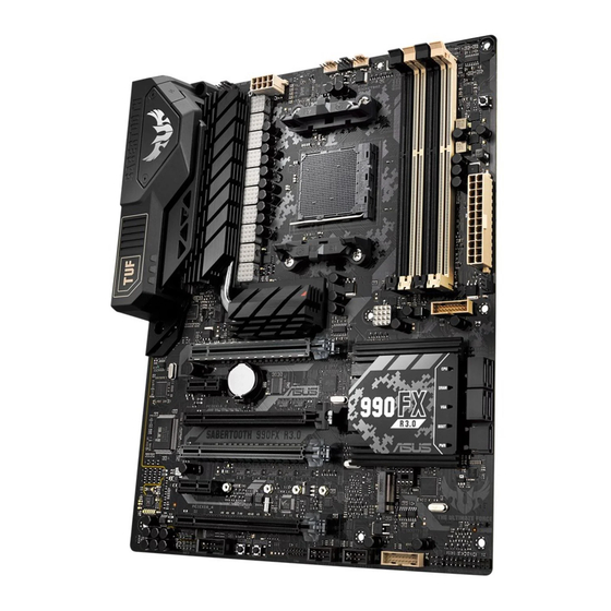
- Page 1 SABERTOOTH 990FX R3.0...
- Page 2 Product warranty or service will not be extended if: (1) the product is repaired, modified or altered, unless such repair, modification of alteration is authorized in writing by ASUS; or (2) the serial number of the product is defaced or missing.
-
Page 3: Table Of Contents
Contents Safety information ...................... vi About this guide ......................vii SABERTOOTH 990FX R3.0 specifications summary ..........ix Package contents ...................... xii Installation tools and components ................. xiii Chapter 1: Product Introduction Motherboard overview ................1-1 1.1.1 Before you proceed ..............1-1 1.1.2... - Page 4 Exit menu ....................3-35 3.11 Updating BIOS ..................3-36 3.11.1 EZ Update ................. 3-36 3.11.2 ASUS EZ Flash 2 Utility ............3-37 3.11.3 ASUS CrashFree BIOS 3 utility..........3-38 Chapter 4: Software Support Installing an operating system ..............4-1 Support DVD information ................4-1 4.2.1...
- Page 5 ® Creating a RAID driver disk ..............5-7 5.2.1 Creating a RAID driver disk in Windows ........5-7 ® ASUS AMD Series SATA Mode Notice ............. 5-8 5.3.1 Installing AHCI driver in Windows XP ........5-8 ® 5.3.2 Converting an existing system drive from IDE mode to AHCI mode.............
-
Page 6: Safety Information
Safety information Electrical safety • To prevent electrical shock hazard, disconnect the power cable from the electrical outlet before relocating the system. • When adding or removing devices to or from the system, ensure that the power cables for the devices are unplugged before the signal cables are connected. If possible, disconnect all power cables from the existing system before you add a device. -
Page 7: About This Guide
Refer to the following sources for additional information and for product and software updates. ASUS website The ASUS website (www.asus.com) provides updated information on ASUS hardware and software products. Optional documentation Your product package may include optional documentation, such as warranty flyers, that may have been added by your dealer. -
Page 8: Conventions Used In This Guide
Conventions used in this guide To ensure that you perform certain tasks properly, take note of the following symbols used throughout this manual. DANGER/WARNING: Information to prevent injury to yourself when trying to complete a task. CAUTION: Information to prevent damage to the components when trying to complete a task. -
Page 9: Sabertooth 990Fx R3.0 Specifications Summary
4 x DIMM, Max. 32GB, DDR3 1866/1600/1333/1066 MHz, ECC, Non-ECC, un-buffered Memory Dual Channel memory architecture Memory Refer to www.asus.com for the Memory QVL (Qualified Vendors Lists) of AM3+/ AM3 CPU. ** Due to OS limitation, when installing total memory of 4GB capacity or more, Windows 32-bit operation system may only recognize less than 3GB. - Page 10 - USB 3.1 Boost featuring speedy USB 3.1 transmission - ASUS SafeSlot - Ai Suite 3 - ASUS UEFI BIOS EZ Mode featuring friendly graphics user interface - USB BIOS Flashback with USB BIOS Flashback Wizard for EZ BIOS download scheduling...
-
Page 11: 1 X Memok! Button
1 x Clear CMOS header 64 Mb Flash ROM, UEFI BIOS, PnP, SLP2.1, DMI2.0, WfM2.0, SM BIOS 2.7, ACPI 2.0a, Multi-language BIOS, ASUS EZ Flash 2, ASUS CrashFree BIOS 3, My Favorites, Quick Note, Last Modified log, F12 PrintScreen, F3... -
Page 12: Package Contents
ASUS SABERTOOTH 990FX R3.0 User manual Support DVD motherboard 4 x Serial ATA 6.0 Gb/s cables 1 x ASUS SLI™ bridge connector 1 x TUF Certification card 1 x TUF Five-year warranty manual 1 x ASUS Q-Shield 1 x Q-Connector (by region) •... -
Page 13: Installation Tools And Components
Installation tools and components 1 bag of screws Philips (cross) screwdriver PC chassis Power supply unit AMD AM3+ CPU AMD AM3+ compatible CPU Fan DDR3 DIMM SATA hard disk drive SATA optical disc drive (optional) Graphics card The tools and components in the table above are not included in the motherboard package. xiii... -
Page 15: Chapter 1: Product Introduction
Chapter 1: Product Introduction Product Introduction Motherboard overview 1.1.1 Before you proceed Take note of the following precautions before you install motherboard components or change any motherboard settings. • Unplug the power cord from the wall socket before touching any component. • Before handling components, use a grounded wrist strap or touch a safely grounded object or a metal object, such as the power supply case, to avoid damaging them due to static electricity. • Hold components by the edges to avoid touching the ICs on them. • Whenever you uninstall any component, place it on a grounded antistatic pad or in the bag that came with the component. • Before you install or remove any component, ensure that the ATX power supply is switched off or the power cord is detached from the power supply. Failure to do so may cause severe damage to the motherboard, peripherals, or components. ASUS SABERTOOTH 990FX R3.0... -
Page 16: Motherboard Layout
1.1.2 Motherboard layout Refer to 1.1.9 Internal connectors and 2.3.1 Rear I/O connection for more information about rear panel connectors and internal connectors. Chapter 1: Product Introduction... -
Page 17: Layout Contents
7. AMD Serial ATA 6.0 Gb/s connectors (7-pin SATA6G_1-5) 1-13 ® 8. M.2 socket 3 1-16 9. Clear RTC RAM (2-pin CLRTC) 1-11 10. System panel connector (20-8 pin PANEL) 1-20 11. Direct Connector (2-pin DRCT) 1-21 12. USB 2.0 connectors (10-1 pin USB1314, USB1112) 1-15 13. TPM connector (14-1 pin TPM) 1-21 14. USB BIOS Flashback button 2-21 15. Power-on button 16. Serial port connector (10-1 pin COM1) 1-16 17. Front panel audio connector (10-1 pin AAFP) 1-18 18. Digital audio connector (4-1 pin SPDIF_OUT) 1-14 ASUS SABERTOOTH 990FX R3.0... -
Page 18: Central Processing Unit (Cpu)
1.1.3 Central Processing Unit (CPU) The motherboard comes with an AM3+ socket designed for AMD FX Series CPU up ® to 8-core, also compatible with AMD socket AM3 for AMD Phenom™ II / Athlon™ II / ® ® Sempron™ 100 Series Processors. Ensure that all power cables are unplugged before installing the CPU. The AM3+ socket has a different pinout design. Ensure that you use a CPU designed for the AM3+/AM3 socket. The CPU fits in only one correct orientation. DO NOT force the CPU into the socket to prevent bending the connectors on the socket and damaging the CPU! Chapter 1: Product Introduction... -
Page 19: System Memory
1.1.4 System memory The motherboard comes with four Double Data Rate 3 (DDR3) Dual Inline Memory Modules (DIMM) slots. A DDR3 module is notched differently from a DDR or DDR2 module. DO NOT install a DDR or DDR2 memory module to the DDR3 slot. Recommended memory configurations ASUS SABERTOOTH 990FX R3.0... -
Page 20: Memory Configurations
• Due to the memory address limitation on 32-bit Windows OS, when you install 4GB ® or more memory on the motherboard, the actual usable memory for the OS can be about 3GB or less. For effective use of memory, we recommend that you do any of the following: a) Use a maximum of 3GB system memory if you are using a 32-bit Windows OS. ® b) Install a 64-bit Windows OS when you want to install 4 GB or more on the ® motherboard. c) For more details, refer to the Microsoft support site at http://support.microsoft. ® com/kb/929605/en-us. • The design of the DIMM fan may vary. Ensure that the DIMM fan fits to the motherboard • Always install the DIMMS with the same CAS Latency. For an optimum compatibility, we recommend that you install memory modules of the same version or data code (D/C) from the same vendor. Check with the vendor to get the correct memory modules. • Hyper DIMM support is subject to the physical characteristics of individual CPUs. Load the X.M.P. or D.O.C.P. settings in the BIOS for the hyper DIMM support. • Visit the ASUS website for the latest QVL. Chapter 1: Product Introduction... -
Page 21: Expansion Slots
1.1.5 Expansion slots Unplug the power cord before adding or removing expansion cards. Failure to do so may cause you physical injury and damage motherboard components. Slot No. Slot Description PCIe 2.0 x16_1 slot (single at x16, dual at x16/x16, triple at x16/x8/x8 mode) PCIe 2.0 x1_1 slot PCIe 2.0 x16_2 slot PCIe 2.0 x16_3 slot PCIe 2.0 x1_2 slot PCIe 2.0 x16_4 slot ASUS SABERTOOTH 990FX R3.0... - Page 22 PCI Express operating mode PCIe 2.0_ PCIe 2.0_ configuration PCIe 2.0x16_3 PCIe 2.0x16_4 x16_1 x16_2 x16 Single VGA/ (Recommend PCIe card for single VGA) Dual VGA/PCIe card 3-way SLI • In single VGA card mode, use the PCIe 2.0 x16_1 slot for a PCI Express x16 graphics card to get better performance. • In CrossFireX™ or SLI™ mode, use the PCIe 2.0 x16_1 and PCIe 2.0 x16_3 slots for PCI Express x16 graphics cards to get better performance. • In 3-way SLI mode, use the PCIe 2.0 x16_1/PCIe 2.0 x16_3/PCIe 2.0 x16_4 slots for PCI Express x16 graphic cards to get better performance. • We recommend that you provide sufficient power when running CrossFireX™ or SLI™ mode. • Connect a chassis fan to the motherboard connector labeled CHA_FAN1/2/3 when using multiple graphics cards for better thermal environment.
-
Page 23: Onboard Buttons
1.1.6 Onboard buttons Onboard buttons allow you to fine-tune performance when working on a bare or open- case system. This is ideal for overclockers and gamers who continually change settings to enhance system performance. Power-on button The motherboard comes with a power-on button that allows you to power up or wake up the system. ASUS SABERTOOTH 990FX R3.0... - Page 24 MemOK! button Installing DIMMs that are not compatible with the motherboard may cause system boot failure, and the DRAM_LED near the MemOK! switch lights continuously. Press and hold the MemOK! button until the DRAM_LED starts blinking to begin automatic memory compatibility tuning for successful boot. • The MemOK! switch does not function under Windows™ OS environment. • During the tuning process, the system loads and tests failsafe memory settings. It takes about 30 seconds for the system to test one set of failsafe settings. If the test fails, the system reboots and test the next set of failsafe settings. • Due to memory tuning requirement, the system automatically reboots when each timing set is tested. Replace the DIMMs with ones recommended in the Memory QVL (Qualified Vendors Lists) on the ASUS website at www.asus.com. • If you turn off the computer and replace DIMMs during the tuning process, the system continues memory tuning after turning on the computer. To stop memory tuning, turn off the computer and unplug the power cord for about 5–10 seconds. • If your system fails to boot up due to BIOS overclocking, press the MemOK! switch to boot and load the BIOS default settings. A message will appear during POST reminding you that the BIOS has been restored to its default settings. • We recommend that you download and update to the latest BIOS version from the ASUS website at www.asus.com after using the MemOK! function. Chapter 1: Product Introduction 1-10...
-
Page 25: Jumpers
1.1.7 Jumpers Clear RTC RAM (2-pin CLRTC) This jumper allows you to clear the Real Time Clock (RTC) RAM in CMOS. You can clear the CMOS memory of date, time, and system setup parameters by erasing the CMOS RTC RAM data. The onboard button cell battery powers the RAM data in CMOS, which include system setup information such as system passwords. To erase the RTC RAM: Turn OFF the computer and unplug the power cord. Short-circuit pin 1-2 with a metal object or jumper cap for about 5-10 seconds. Plug the power cord and turn ON the computer. Hold down the <Del> key during the boot process and enter BIOS setup to re-enter data. Except when clearing the RTC RAM, never short-circuit the CLRTC jumper. Shorting the CLRTC jumper will cause system boot failure! • If the steps above do not help, remove the onboard battery and move the jumper again to clear the CMOS RTC RAM data. After clearing the CMOS, reinstall the battery. • You do not need to clear the RTC when the system hangs due to overclocking. For system failure due to overclocking, use the CPU Parameter Recall (C.P.R.) feature. Shut down and reboot the system, then the BIOS automatically resets parameter settings to default values. • Due to chipset behavior, AC power off is required to enable C.P.R. function. You must turn off and on the power supply or unplug and plug the power cord before rebooting the system. ASUS SABERTOOTH 990FX R3.0 1-11... -
Page 26: Onboard Leds
1.1.8 Onboard LEDs USB BIOS Flashback LED (FLBK_LED) The BIOS Flashback LED flashes when you press the BIOS Flashback button for BIOS update. Chapter 1: Product Introduction 1-12... -
Page 27: Internal Connectors
If you installed Serial ATA hard disk drives, you can create a RAID 0, 1, 5, and 10 configuration through the onboard AMD SB950 chipset. ® • These connectors are set to [AHCI Mode] by default. If you intend to create a Serial ATA RAID set using these connectors, set the SATA Mode item in the BIOS to [RAID Mode]. Refer to section 3.6.4 SATA Configuration for details. • Before creating a RAID set, refer to section 5.1 RAID configurations or the manual bundled in the motherboard support DVD. • When creating a RAID set, set the SATA6G_5 connectors to [IDE Mode] to ensure that the system recognizes your ODD device. • When using NCQ, set the SATA Mode in the BIOS to [AHCI Mode]. Refer to section 3.6.4 SATA Configuration for details. • You must install Windows XP Service Pack 3 or later versions before using Serial ® ATA hard disk drives. The Serial ATA RAID feature is available only if you are using Windows XP SP3 or later versions. ® ASUS SABERTOOTH 990FX R3.0 1-13... -
Page 28: Usb 3.0 Connector (20-1 Pin Usb3_E56, Usb3_E78)
USB 3.0 connector (20-1 pin USB3_E56, USB3_E78) This connector is for the additional USB 3.0 ports, and complies with the USB 3.0 specification that supports up to 480 MBps connection speed. If the USB 3.0 front panel cable is available from your system chassis, with this USB 3.0 connector, you can have a front panel USB 3.0 solution. Digital audio connector (4-1 pin SPDIF_OUT) This connector is for an additional Sony/Philips Digital Interface (S/PDIF) port. Connect the S/PDIF Out module cable to this connector, then install the module to a slot opening at the back of the system chassis. The S/PDIF module is purchased separately. Chapter 1: Product Introduction 1-14... - Page 29 USB 2.0 connectors (10-1 pin USB1314, USB1112) These connectors are for USB 2.0 ports. Connect the USB module cable to any of these connectors, then install the module to a slot opening at the back of the system chassis. These USB connectors comply with USB 2.0 specification that supports up to 48 MBps connection speed. Never connect a 1394 cable to the USB connectors. Doing so will damage the motherboard! You can connect the front panel USB cable to the ASUS Q-Connector first, and then install the Q-Connector (USB) to the USB connector onboard if your chassis supports front panel USB ports. The USB 2.0 module is purchased separately. ASUS SABERTOOTH 990FX R3.0 1-15...
-
Page 30: Socket
Serial port connector (10-1 pin COM1) This connector is for a serial (COM) port. Connect the serial port module cable to this connector, then install the module to a slot opening at the back of the system chassis. The COM module is purchased separately. M.2 socket 3 This socket allows you to install an M.2 (NGFF) SSD module. This socket supports PCIe 2.0 x4 M Key design and type 2242/2260/2280/22110 PCIe storage devices. The M.2 (NGFF) SSD module is purchased separately. Chapter 1: Product Introduction 1-16... - Page 31 CPU and chassis fan connectors (4-pin CPU_FAN, 4-pin CPU_OPT, 4-pin CHA_ FAN1-3, 4-pin W_PUMP) Connect the fan cables to the fan connectors on the motherboard, ensuring that the black wire of each cable matches the ground pin of the connector. DO NOT forget to connect the fan cables to the fan connectors. Insufficient air flow inside the system may damage the motherboard components. These are not jumpers! Do not place jumper caps on the fan connectors! • The CPU_FAN connector supports the CPU fan of maximum 1A (12 W) fan power. • W_PUMP function support depends on water cooling device. When using a water cooling device, connect the device’s fan connector(s) to the motherboard’s CPU_FAN connector, and the water pump connector to the W_PUMP connector. • If you install two VGA cards, we recommend that you plug the rear chassis fan cable to the motherboard connector labeled CHA_FAN1, CHA_FAN2, or CHA_FAN3 for better thermal environment. ASUS SABERTOOTH 990FX R3.0 1-17...
- Page 32 Front panel audio connector (10-1 pin AAFP) This connector is for a chassis-mounted front panel audio I/O module that supports either HD Audio or legacy AC`97 audio standard. Connect one end of the front panel audio I/O module cable to this connector. • We recommend that you connect a high-definition front panel audio module to this connector to avail of the motherboard’s high-definition audio capability. • If you want to connect a high-definition or an AC’97 front panel audio module to this connector, set the Front Panel Type item in the BIOS setup to [HD] or [AC97]. Chapter 1: Product Introduction 1-18...
- Page 33 ATX power connectors (24-pin EATXPWR, 8-pin EATX12V) These connectors are for ATX power supply plugs. The power supply plugs are designed to fit these connectors in only one orientation. Find the proper orientation and push down firmly until the connectors completely fit. • For a fully configured system, we recommend that you use a power supply unit (PSU) that complies with ATX 12 V Specification 2.0 (or later version) and provides a minimum power of 350 W. • DO NOT forget to connect the 4-pin/8-pin EATX12 V power plug. Otherwise, the system will not boot. • We recommend that you use a PSU with a higher power output when configuring a system with more power-consuming devices. The system may become unstable or may not boot up if the power is inadequate. • If you want to use two or more high-end PCI Express x16 cards, use a PSU with 1000W power or above to ensure the system stability. ASUS SABERTOOTH 990FX R3.0 1-19...
-
Page 34: System Panel Connector (20-8 Pin Panel)
System panel connector (20-8 pin PANEL) This connector supports several chassis-mounted functions. • System power LED (2-pin or 3-1 pin PLED) The 2-pin or 3-1 pin connector is for the system power LED. Connect the chassis power LED cable to this connector. The system power LED lights up when you turn on the system power, and blinks when the system is in sleep mode. • Hard disk drive activity LED (2-pin HDD_LED) This 2-pin connector is for the HDD Activity LED. Connect the HDD Activity LED cable to this connector. The HDD LED lights up or flashes when data is read from or written to the HDD. • System warning speaker (4-pin SPEAKER) This 4-pin connector is for the chassis-mounted system warning speaker. The speaker allows you to hear system beeps and warnings. • ATX power button/soft-off button (2-pin PWRSW) This connector is for the system power button. Pressing the power button turns the system on or puts the system in sleep or soft-off mode depending on the operating system settings. Pressing the power switch for more than four seconds while the system is ON turns the system OFF. • Reset button (2-pin RESET) This 2-pin connector is for the chassis-mounted reset button for system reboot without turning off the system power. Chapter 1: Product Introduction 1-20... -
Page 35: Direct Connector (2-Pin Drct)
TPM connector (14-1 pin TPM) This connector supports a Trusted Platform Module (TPM) system, which securely store keys, digital certificates, passwords and data. A TPM system also helps enhance network security, protect digital identities, and ensures platform integrity. Direct Connector (2-pin DRCT) This connector is for the chassis-mounted button that supports the DirectKey function. Connect the button cable that supports DirectKey, from the chassis to this connector on the motherboard. Ensure that your chassis comes with the button cable that supports the DirectKey feature. Refer to the technical documentation that came with the chassis for details. ASUS SABERTOOTH 990FX R3.0 1-21... - Page 36 Chapter 1: Product Introduction 1-22...
-
Page 37: Chapter 2: Basic Installation
The diagrams in this section are for reference only. The motherboard layout may vary with models, but the installation steps are the same for all models. Install the ASUS Q-Shield to the chassis rear I/O panel. Place the motherboard into the chassis, ensuring that its rear I/O ports are aligned to the chassis’... - Page 38 Place nine screws into the holes indicated by circles to secure the motherboard to the chassis. DO NOT overtighten the screws! Doing so can damage the motherboard. Chapter 2: Basic Installation...
-
Page 39: Cpu Installation
CPU designed for the AM3+ socket. The CPU fits in only one correct orientation. DO NOT force the CPU into the socket to prevent bending the connectors on the socket and damaging the CPU! ASUS SABERTOOTH 990FX R3.0... -
Page 40: Cpu Heatsink And Fan Assembly Installation
2.1.3 CPU heatsink and fan assembly installation Apply the Thermal Interface Material to the CPU heatsink and CPU before you install the heatsink and fan if necessary. To install the CPU heatsink and fan assembly Chapter 2: Basic Installation... - Page 41 ASUS SABERTOOTH 990FX R3.0...
-
Page 42: Dimm Installation
2.1.4 DIMM installation To remove a DIMM Chapter 2: Basic Installation... -
Page 43: Atx Power Connection
ATX power connection • DO NOT connect the 4-pin power plug only, the motherboard may overheat under heavy usage. • Ensure to connect the 8-pin power plug, or connect both the 8-pin and 4-pin power plugs. ASUS SABERTOOTH 990FX R3.0... -
Page 44: Sata Device Connection
2.1.6 SATA device connection Chapter 2: Basic Installation... -
Page 45: Front I/O Connector
2.1.7 Front I/O connector To install ASUS Q-Connector To install USB 2.0 connector To install front panel audio connector AAFP USB 2.0 To install USB 3.0 connector USB 3.0 ASUS SABERTOOTH 990FX R3.0... -
Page 46: Expansion Card Installation
2.1.8 Expansion card installation To install PCIe x16 cards To install PCIe x1 cards Chapter 2: Basic Installation 2-10... -
Page 47: Bios Update Utility
BIOS Flashback function is enabled. Refer to section 1.1.8 Onboard LEDs for more information of the Flashback LED. If the system fails to boot after flashing the BIOS, unplug the power core and restart the system. ASUS SABERTOOTH 990FX R3.0 2-11... - Page 48 • Updating BIOS may have risks. If the BIOS program is damaged during the process and results to the system’s failure to boot up, please contact your local ASUS Service Center. Chapter 2: Basic Installation...
-
Page 49: Motherboard Rear And Audio Connections
USB 3.1 devices to USB 3.1 ports for faster and better performance. • Due to USB 3.0/USB 3.1 controller limitation, USB 3.0/USB 3.1 devices can only be used under Windows 7 OS environment and after the USB 3.0/USB 3.1 driver ® installation. ASUS SABERTOOTH 990FX R3.0 2-13... - Page 50 * LAN ports LED indications Activity Link LED Speed LED Status Description Status Description ACT/LINK SPEED No link 10 Mbps connection Orange Linked Orange 100 Mbps connection Orange (Blinking) Data activity Green 1 Gbps connection Orange (Blinking Ready to wake up LAN port then steady) from S5 mode...
-
Page 51: Audio I/O Connections
2.3.2 Audio I/O connections Audio I/O ports Connect to Headphone and Mic Connect to Stereo Speakers Connect to 2.1 channel Speakers ASUS SABERTOOTH 990FX R3.0 2-15... - Page 52 Connect to 4.1 channel Speakers Connect to 5.1 channel Speakers If you are using Windows 8.1/10 platform, use only the light blue audio port for Side ® Speaker Out in a 6-channel configuration. Chapter 2: Basic Installation 2-16...
-
Page 53: Starting Up For The First Time
If you do not see anything within 30 seconds from the time you turned on the power, the system may have failed a power-on test. Check the jumper settings and connections or call your retailer for assistance. ASUS SABERTOOTH 990FX R3.0 2-17... -
Page 54: Turning Off The Computer
BIOS Beep Description One short beep VGA detected Quick boot set to disabled No keyboard detected One continuous beep followed by two No memory detected short beeps then a pause (repeated) One continuous beep followed by three No VGA detected short beeps One continuous beep followed by four Hardware component failure... -
Page 55: Chapter 3: Bios Setup
BIOS Setup Knowing BIOS The new ASUS UEFI BIOS is a Unified Extensible Interface that complies with UEFI architecture, offering a user-friendly interface that goes beyond the traditional keyboard- only BIOS controls to enable a more flexible and convenient mouse input. You can easily navigate the new UEFI BIOS with the same smoothness as your operating system. -
Page 56: Bios Setup Program
RTC RAM. • The BIOS setup program does not support the Bluetooth devices. Please visit ASUS website for the detailed BIOS content manual. BIOS menu screen The BIOS Setup program can be used under two modes: EZ Mode and Advanced Mode. -
Page 57: Ez Mode
Power saving selected mode mode • The boot device options vary depending on the devices you installed to the system. • The Boot Menu(F8) button is available only when the boot device is installed to the system. ASUS SABERTOOTH 990FX R3.0... -
Page 58: Advanced Mode
3.2.2 Advanced Mode The Advanced Mode provides advanced options for experienced end-users to configure the BIOS settings. The figure below shows an example of the Advanced Mode. Refer to the following sections for the detailed configurations. To access the Advanced Mode, click Exit, then select Advanced Mode or press the <F7> hotkey. -
Page 59: Menu Items
Quick Note button This button allows you to enter notes of the activities that you have done in BIOS. Last Modified button This button shows the items that you last modified and saved in BIOS Setup. ASUS SABERTOOTH 990FX R3.0... -
Page 60: My Favorites
My Favorites My Favorites is your personal space where you can easily save and access your favorite BIOS items. Adding items to My Favorites To add frequently-used BIOS items to My Favorites: Use the arrow keys to select an item that you want to add. When using a mouse, hover the pointer to the item. -
Page 61: Main Menu
RAM to clear the BIOS password. See section 1.1.7 Jumpers for information on how to erase the RTC RAM. • The Administrator or User Password items on top of the screen show the default Not Installed. After you set a password, these items show Installed. ASUS SABERTOOTH 990FX R3.0... -
Page 62: Administrator Password
Administrator Password If you have set an administrator password, we recommend that you enter the administrator password for accessing the system. Otherwise, you might be able to see or change only selected fields in the BIOS setup program. To set an administrator password: Select the Administrator Password item and press <Enter>. -
Page 63: Ai Tweaker Menu
Displays the target CPU speed. Current Memory Frequency : xxxxMHz Displays the current memory frequency. Current NB Frequency : xxxxMHz Displays the current NB frequency. Current HT Link Speed : xxxxMHz Displays the current HT link speed. ASUS SABERTOOTH 990FX R3.0... - Page 64 Ai Overclock Tuner [Auto] Allows you to select the CPU overclocking options to achieve the desired CPU internal frequency. Select any of these preset overclocking configuration options: [Auto] Loads the optimal settings for the system. [Manual] Allows you to individually set overclocking parameters. [D.O.C.P.] Allows you to select a DRAM O.C.
-
Page 65: Dram Timing Control
EPU Power Saving Mode [Disabled] The ASUS EPU (Energy Processing Unit) sets the CPU in its minimum power consumption settings. Enable this item to set lower CPU core/cache voltage and achieve the best energy saving condition. Configuration options: [Disabled] [Enabled] The following item appears only when you set EPU Power Saving Mode to [Enabled]. - Page 66 VRM efficiency. [Standard] Proceeds phase control depending on the CPU loading. [Optimized] Loads the ASUS optimized phase tuning profile. [Extreme] Proceeds the full phase mode. [Manual Adjustment] Allows manual adjustment. CPU Voltage Frequency [Auto] Switching frequency will affect the VRM transient response and component thermal.
- Page 67 CPU/NB Offset Voltage [Auto] This item allows you to set the CPU/NB Offset voltage. Use the <+> or <-> to adjust the value. The values range from 0.006250V to 0.700000V with an interval of 0.06250V. ASUS SABERTOOTH 990FX R3.0 3-13...
- Page 68 CPU & NB Voltage The following items appear only when you set to [Manual Mode]. CPU Manual Voltage [Auto] This item allows you to set a fixed CPU voltage. Use the <+> or <-> to adjust the value. The values range from 0.006250V to 2.075000V with an interval of 0.06250V. CPU/NB Manual Voltage [Auto] This item allows you to set a fixed CPU/NB voltage.
-
Page 69: Advanced Menu
The items shown in submenu may be different due to the CPU you installed. Cool‘n’Quiet [Always Disabled] This item allows you to enable or disable the Cool ‘n’ Quiet function. Configuration options: [Disabled by CPU] [Always Enabled] [Always Disabled] ASUS SABERTOOTH 990FX R3.0 3-15... -
Page 70: North Bridge Configuration
C1E [Disabled] This item allows your system to utilize the AMD specific ACPI states to save power consumption. Configuration options: [Disabled] [Enabled] SVM [Enabled] [Disabled] Disables this function. [Enabled] Enables the AMD Secure Virtual Machine mode. 3.6.2 North Bridge Configuration IOMMU [Disabled] Allows you to enable or disable the input/output memory management unit (IOMMU) Configuration options: [Enabled] [Disabled]... -
Page 71: South Bridge Configuration
Allows you to select unganged DRAM mode (64-bit width). [Enabled]: Unganged mode. [Disabled]: Ganged mode. 3.6.3 South Bridge Configuration HPET [Enabled] Allows you to enable or disable the High Precision Event Timer (HPET). Configuration options: [Enabled] [Disabled] ASUS SABERTOOTH 990FX R3.0 3-17... -
Page 72: Sata Configuration
3.6.4 SATA Configuration While entering Setup, the BIOS automatically detects the presence of SATA devices. The SATA Port items show Not Present if no SATA device is installed to the corresponding SATA port. SB SATA Configuration Allows you to set SATA options. OnChip SATA Channel [Enabled] Allows you to enable or disable serial ATA. - Page 73 SATA Port1 - Port4. The following item appears only when you set SATA Port1 - Port4 to [IDE] or [AHCI]. S.M.A.R.T. Status Check [Enabled] [Disabled] Disables the S.M.A.R.T feature. [Enabled] Enables the S.M.A.R.T feature. ASUS SABERTOOTH 990FX R3.0 3-19...
-
Page 74: Usb Configuration
3.6.5 USB Configuration The items in this menu allow you to change the USB-related features. The USB Devices item shows the auto-detected values. If no USB device is detected, the item shows None. Legacy USB Support [Enabled] [Disabled] The USB devices can be used only for the BIOS setup program. [Enabled] Enables the support for USB devices on legacy operating systems (OS). -
Page 75: Cpu Core On/Off Function
The following items appear only when you set CPU Core Activation to [Manual]. 3rd & 4th Core [Enabled] Configuration options: [Disabled] [Enabled] 5th & 6th Core [Enabled] Configuration options: [Disabled] [Enabled] 3.6.7 Onboard Devices Configuration ASUS SABERTOOTH 990FX R3.0 3-21... - Page 76 Asmedia USB 3.0 Controller [Enabled] [Disabled] Disables the controller. [Enabled] Enables the front USB 3.0 controller. Asmedia USB 3.1 Controller 1 [Enabled] [Disabled] Disables the controller. [Enabled] Enables the rear USB 3.1 controller. Asmedia USB 3.1 Controller 2 [Enabled] [Disabled] Disables the controller.
-
Page 77: Serial Port Configuration
Sets the front panel audio connector (AAFP) mode to legacy AC’97 [HD] Sets the front panel audio connector (AAFP) mode to high definition audio. SPDIF Out Type [SPDIF] [SPDIF] Sets to [SPDIF] for SPDIF audio output. [HDMI] Sets to [HDMI] for HDMI audio output. ASUS SABERTOOTH 990FX R3.0 3-23... -
Page 78: Apm
3.6.8 ErP Ready [Disabled] Allows the BIOS to switch off some power at S5 to get the system ready for ErP requirement. When this item is set to [Enabled], all other PME options will be switched off. Configuration options: [Disabled] [Enabled] Restore AC Power Loss [Power Off] [Power Off] The system goes into off state after an AC power loss. -
Page 79: Network Stack
This item allows user to disable or enable the UEFI network stack. Configuration options: [Disabled] [Enabled] The following item appears only when you set Network Stack to [Enabled]. Ipv4 PXE Support [Enabled] Configuration options: [Disabled] [Enabled] Ipv6 PXE Support [Enabled] Configuration options: [Disabled] [Enabled] ASUS SABERTOOTH 990FX R3.0 3-25... -
Page 80: Monitor Menu
Monitor menu The Monitor menu displays the system temperature/power status, and allows you to change the fan settings. Scroll down on the menu to display more items. CPU Temperature / MB Temperature [xxx°C/xxx°F] The onboard hardware monitor automatically detects and displays the CPU and motherboard temperatures. - Page 81 Chassis Fan 1-3 Speed Low Limit [600 RPM] This item allows you to disable or set the chassis fan warning speed. Configuration options: [Ignore] [100 RPM] [200 RPM] [300 RPM] [400 RPM] [500 RPM] [600 RPM] ASUS SABERTOOTH 990FX R3.0 3-27...
- Page 82 Chassis Fan 1-3 Profile [Standard] This item allows you to set the appropriate performance level of the chassis fan. [Standard] Sets to [Standard] to make the chassis fan automatically adjust depending on the chassis temperature. [Silent] Sets to [Silent] to minimize the fan speed for quiet chassis fan operation. [Turbo] Sets to [Turbo] to achieve maximum chassis fan speed.
-
Page 83: Boot Menu
The Boot menu items allow you to change the system boot options. Scroll down on the menu to display more items. Fast Boot [Enabled] [Disabled] Allows your system to go back to its normal boot speed. [Enabled] Allows your system to accelerate the boot speed. ASUS SABERTOOTH 990FX R3.0 3-29... - Page 84 The following items appear only when you set the Fast Boot to [Enabled]. USB Support [Partial Initialization] [Disabled] All USB devices will not be available until OS boot up for a fastest POST time. [Full Initialization] All USB devices will be available during POST. This process will extend the POST time.
- Page 85 Boot from Storage Devices [Legacy OpROM first] This item allows you to select the type of storage devices that you want to launch. Configuration options: [Both, Legacy OpROM first] [Both, UEFI first] [Legacy OpROM first] [UEFI driver first] [Ignore] ASUS SABERTOOTH 990FX R3.0 3-31...
-
Page 86: Secure Boot
Boot from PCI-E/PCI Expansion Devices [Legacy OpROM first] This item allows you to select the type of PCI-E/PCI expansion devices that you want to launch. Configuration options: [Legacy OpROM first] [UEFI driver first] Secure Boot This item allows you to configure the Windows Secure Boot settings and manage its keys to ®... - Page 87 Append dbx from File Allows you to load the additional dbx from a storage device so that more db’s images cannot be loaded. The dbx file must be formatted as a UEFI variable structure with time-based authenticated variable. ASUS SABERTOOTH 990FX R3.0 3-33...
-
Page 88: Tool Menu
<Enter> to display the submenu. ASUS EZ Flash 2 Utility Allows you to run ASUS EZ Flash 2. Press <Enter> to launch the ASUS EZ Flash 2 screen. For more details, see section 3.11.2 ASUS EZ Flash 2 Utility. -
Page 89: Exit Menu
This option allows you to enter the EZ Mode screen. Launch EFI Shell from filesystem device This option allows you to attempt to launch the EFI Shell application (shellx64.efi) from one of the available devices that have a filesystem. ASUS SABERTOOTH 990FX R3.0 3-35... -
Page 90: Updating Bios
® ASUS EZ Flash 2: Updates the BIOS using a USB flash drive. ASUS CrashFree BIOS 3: Restores the BIOS using the motherboard support DVD or a USB flash drive when the BIOS file fails or gets corrupted. 3.11.1... -
Page 91: Asus Ez Flash 2 Utility
3.11.2 ASUS EZ Flash 2 Utility The ASUS EZ Flash 2 feature allows you to update the BIOS without using an OS-based utility. Press <Enter> to launch the EZ Flash 2 screen. Before you start using this utility, download the latest BIOS file from the ASUS website at www.asus.com. -
Page 92: Asus Crashfree Bios 3 Utility
3.11.3 ASUS CrashFree BIOS 3 utility The ASUS CrashFree BIOS 3 is an auto recovery tool that allows you to restore the BIOS file when it fails or gets corrupted during the updating process. You can restore a corrupted BIOS file using the motherboard support DVD or a USB flash drive that contains the updated BIOS file. -
Page 93: Chapter 4: Software Support
Place the Support DVD into the optical drive. In the AutoPlay dialog box, Click Run ASSETUP.EXE. If the AutoPlay dialog box does not appear, browse the contents of the support DVD and double-Click \\bin\ASSETUP.EXE to launch the ASUS motherboard support DVD main menu. ASUS SABERTOOTH 990FX R3.0... -
Page 94: Obtaining The Software Manuals
Click an item to open the folder of the user guide Click to display product related information Click to display the ASUS contact information Click to browse the file list of the support CD Click to install the selected items 4.2.2 Obtaining the software manuals The software manuals are included in the support DVD. -
Page 95: Software Information
View the online help or readme file that came with the software application for more information. AI Suite 3 AI Suite 3 is an all-in-one interface that integrates several ASUS utilities and allows you to launch and operate these utilities simultaneously. Installing AI Suite 3 Ensure that you have an Administrator account before installing AI Suite 3 in Windows ®... - Page 96 Windows ® 7 OS From the Desktop, click or tap Start > All Programs > ASUS > AI Suite 3 > AI Suite 3. You can also launch AI Suite in Windows 7 by clicking or tapping on the Notification ®...
- Page 97 Some functions in the AI Suite 3 main menu in this user guide may vary depending on the motherboard model. • Refer to the software manual in the support DVD or visit the ASUS website at www.asus.com for detailed software configuration. ASUS SABERTOOTH 990FX R3.0...
-
Page 98: Thermal Radar 2
4.4.1 Thermal Radar 2 Thermal Radar 2 lets you control fans, monitor your graphics card temperature and other key components in real time, or auto-tune your thermal settings. Thermal Tuning This function optimizes your system’s cooling solution based on your system’s current thermal settings. - Page 99 Allows you to configure the thermal settings of an installed ASUS graphics card. • The VGA tab on Thermal Radar 2 appears only when you install an optional ASUS graphics card into your system. • The VGA feature of Thermal Radar 2 supports ASUS NVidia 700/900 Series and AMD R7/R9 Series graphics card only.
- Page 100 VGA - RPM Mode Allows you to manually adjust the fan’s speed (in rpm). Move the slider up or down to adjust the settings Click to save a new profile Click to load a saved profile Thermal Status Displays the current status of the thermal condition of your system. Click or tap to run the assessment report of your current thermal...
- Page 101 Click or tap to scroll down/up DIGI+ Power Control ASUS DIGI+ Power Control features the revolutionary and innovative digital VRM and DRAM Voltage controllers. These controllers offers ultra-precise memory and voltage tuning for optimal system efficiency, stability and performance. Click or tap to go the...
- Page 102 DIGI+PowerControl - CPU Click or tap to go back Click or tap to switch Click or tap to undo Click or tap to apply between items the changes the changes to the previous screen DIGI+PowerControl - DRAM Click or tap to go back Click or tap to apply Click or tap to undo to the previous screen...
- Page 103 DIGI+PowerControl - GPU Click or tap to apply Click or tap to go back Click or tap to undo the changes to the previous screen the changes ASUS SABERTOOTH 990FX R3.0 4-11...
-
Page 104: Usb 3.1 Boost
4.4.2 USB 3.1 Boost USB 3.1 Boost technology supports UASP (USB Attached SCSI Protocol) that automatically speeds up the transfer rates of your USB storage devices. Launching USB 3.1 Boost To launch USB 3.1 Boost, cclick on the left of the AI Suite 3 main menu, then select USB 3.1 Boost. -
Page 105: Ez Update
Click or tap to automatically update your motherboard driver, software and firmware Click or tap to Click or tap to Click or tap to search and select a boot logo update the BIOS select the BIOS file ASUS SABERTOOTH 990FX R3.0 4-13... - Page 106 Manually update the BIOS and selecting a boot logo Click or tap to search an image file for your boot logo Click or tap to go back to Click or tap to proceed the updating EZ Update main screen BIOS and boot logo After you click or tap BIOS Update button, click or tap Flash to update the BIOS and upload the boot logo in your system.
-
Page 107: System Information
AI Suite 3 main menu, then select System Information. Viewing the motherboard information Click or tap the MB tab to view the motherboard’s information. Viewing the CPU information Click or tap the CPU tab to view the processor’s information. ASUS SABERTOOTH 990FX R3.0 4-15... - Page 108 Viewing the SPD information Click or tap the SPD tab to view the memory’s information. Chapter 4: Software Support 4-16...
-
Page 109: Usb Bios Flashback
In the Download Setting field, tick Schedule (days) then select the number of days for the BIOS download schedule. Click or tap Apply to save the BIOS download schedule. Click or tap Cancel to cancel the download schedule. ASUS SABERTOOTH 990FX R3.0 4-17... - Page 110 After the utility detects a new BIOS, click or tap from the Save to: field, select the USB flash drive, then click or tap Download. SABERTOOTH 990FX R3.0 After the download is complete, click or tap OK. Chapter 4: Software Support 4-18...
-
Page 111: Push Notice
Push Notice Tap Push Scan then tap the name of your computer that you want to pair with. To pair your computer and smart device, ensure that both are connected to the same wireless network. ASUS SABERTOOTH 990FX R3.0 4-19... - Page 112 Setting up PC Mode alerts of your computer This feature allows you to restart, shut down, or put your computer to sleep mode and sends an alert to your smart device. Tick these to enable mode alerts Tick to select the smart device Set the day and time to enable the PC modes...
- Page 113 Push Notice. Push Notice Tap to delete PC Tap to view PC alerts mode alerts Tap to view PC status alerts Tap to view PC sent messages Tap to scan more host computers ASUS SABERTOOTH 990FX R3.0 4-21...
-
Page 114: Version
4.4.7 Version Displays the installed software or utilities and their current version. Chapter 4: Software Support 4-22... -
Page 115: Turbo Lan
Adapter Info: Displays the information about the installed network adapter in your • system. • Online Budgets: Allows you to set an online budget time to your network adapters. • Traffic Analysis: Allows you to assign protocols and programs in one set. ASUS SABERTOOTH 990FX R3.0 4-23... -
Page 116: Audio Configurations
Audio configurations The Realtek audio CODEC provides 8-channel audio capability to deliver the ultimate audio ® experience on your computer. The software provides Jack-Sensing function, S/PDIF Out support, and interrupt capability. The CODEC also includes the Realtek proprietary UAJ ® ®... - Page 117 Line Out port then Click Next. If you select Headphone, Click to select the type of headphone installed then Click OK. If you select Front Speaker Out, Click to select the type of speaker installed then Click OK. ASUS SABERTOOTH 990FX R3.0 4-25...
- Page 118 Chapter 4: Software Support 4-26...
-
Page 119: Chapter 5: Raid Support
With the RAID 10 configuration you get all the benefits of both RAID 0 and RAID 1 configurations. Use four new hard disk drives or use an existing drive and three new drives for this setup. ASUS SABERTOOTH 990FX R3.0... -
Page 120: Installing Serial Ata Hard Disks
5.1.2 Installing Serial ATA hard disks The motherboard supports Serial ATA hard disk drives. For optimal performance, install identical drives of the same model and capacity when creating a disk array. To install the SATA hard disks for a RAID configuration: Install the SATA hard disks into the drive bays. -
Page 121: Amd ® Option Rom Utility
The RAID BIOS setup screens shown in this section are for reference only and may not exactly match the items on your screen. To create a RAID volume using more than four hard disk drives, ensure that the SATA connectors 5/6 are set to [RAID] mode. ASUS SABERTOOTH 990FX R3.0... -
Page 122: Creating A Raid Volume
Creating a RAID volume To create a RAID volume: In the Main Menu, press <2> to enter the LD View / LD Define Menu function. Press <Ctrl> + <C>, and the following screen appears. Option ROM Utility (c) 2009 Advanced Micro Devices, Inc. [ LD Define Menu ] LD No LD Name... -
Page 123: Deleting A Raid Configuration
[PaUp/PaDn] Switch page [Del/Alt+D] Delete LD The utility prompts the following messages: Press Ctrl-Y to delte the data in the disk! or press any other key to abort... Press <Ctrl> + <Y> to delete the RAID volume. ASUS SABERTOOTH 990FX R3.0... - Page 124 Displaying a RAID set information To display a RAID set information: In the Main Menu, press <2> to enter the LD View / LD Define Menu function. Select a RAID item and press <Enter> to display its information. Option ROM Utility (c) 2009 Advanced Micro Devices, Inc. [ View LD Defination Menu ] LD No LD Name...
-
Page 125: Creating A Raid Driver Disk
RAID driver from the support DVD to the USB flash drive. To set up a Windows UEFI operating system under RAID mode, ensure to load the UEFI ® driver for your optical drive. ASUS SABERTOOTH 990FX R3.0... -
Page 126: Asus Amd Series Sata Mode Notice
ASUS AMD Series SATA Mode Notice The SATA6G_1-4 and SATA6G_5 connectors of this motherboard are set to AHCI mode by default to enhance the SATA performance. For Windows XP operating system, load the AMD AHCI 32/64 bit WinXP Driver with a ®... -
Page 127: Chapter 6: Multiple Gpu Support
AMD CrossFireX graphics cards to your system. To uninstall existing graphics card drivers: Close all current applications. For Windows XP, go to Control Panel > Add/Remove Programs. For Windows 7, go to Control Panel > Programs and Features. Select your current graphics card driver/s. For Windows XP, select Add/Remove. For Windows 7, select Uninstall. Turn off your computer. ASUS SABERTOOTH 990FX R3.0... -
Page 128: Installing Two Crossfirex™ Graphics Cards
6.1.3 Installing two CrossFireX™ graphics cards The following pictures are for reference only. The graphics cards and the motherboard layout may vary with models, but the installation steps remain the same. Prepare two CrossFireX-ready graphics cards. Insert the two graphics card into the PCIEX16 slots. - Page 129 Connect two independent auxiliary power sources from the power supply to the two graphics cards separately. Connect a VGA or a DVI cable to the graphics card. ASUS SABERTOOTH 990FX R3.0...
-
Page 130: Installing The Device Drivers
6.1.4 Installing the device drivers Refer to the documentation that came with your graphics card package to install the device drivers. Ensure that your PCI Express graphics card driver supports the AMD® CrossFireX™ technology. Download the latest driver from the AMD website (www.amd.com). 6.1.5 Enabling the AMD CrossFireX™... - Page 131 Enabling Dual CrossFireX technology In the Catalyst Control Center window, click Performance > AMD CrossFireX Select Enable CrossFireX Select a GPU combination from the drop-down list. Click Apply to save and activate the GPU settings made. ASUS SABERTOOTH 990FX R3.0...
-
Page 132: Nvidia ® Sli ® Technology
NVIDIA technology ® ® The motherboard supports the NVIDIA (Scalable Link Interface) technology that allows ® ® you to install multi-graphics processing units (GPU) graphics cards. Follow the installation procedures in this section. 6.2.1 Requirements • In SLI mode, you should have two identical SLI-ready graphics cards that are NVIDIA ® certified. • Ensure that your graphics card driver supports the NVIDIA SLI technology. Download the latest driver from the NVIDIA website at www.nvidia.com. • Ensure that your power supply unit (PSU) can provide at least the minimum power required by your system. -
Page 133: Installing The Device Drivers
Connect a VGA or a DVI cable to the graphics card. SLI bridge Goldfingers 6.2.3 Installing the device drivers Refer to the documentation that came with your graphics card package to install the device drivers. Ensure that your PCI Express graphics card driver supports the NVIDIA SLI® technology. ® Download the latest driver from the NVIDIA website (www.nvidia.com). ASUS SABERTOOTH 990FX R3.0... -
Page 134: Enabling The Nvidia ® Sli ® Technology
6.2.4 Enabling the NVIDIA technology ® ® After installing your graphics cards and the device drivers, enable the SLI feature in NVIDIA ® Control Panel under the Windows 7 operating system. ® Launching the NVIDIA Control Panel You can launch the NVIDIA Control Panel by the following two methods. Right click on the empty space of the Windows desktop and select NVIDIA Control ® Panel. The NVIDIA Control Panel window appears (See Step B3). B1. If you cannot see the NVIDIA Control Panel item in step (A), select Screen Resolution. From the Screen Resolution window, click Advanced settings. Chapter 6: Multiple GPU Support... - Page 135 B3. The NVIDIA Control Panel window appears. Enabling SLI settings From the NVIDIA Control Panel window, select Configure SLI, Surround, PhysX. In the Quad-SLI enabled, click Maximize 3D Performance SLI to set the display for viewing SLI rendered content. When done, click Apply. ASUS SABERTOOTH 990FX R3.0...
- Page 136 Chapter 6: Multiple GPU Support 6-10...
-
Page 137: Appendix
Consult the dealer or an experienced radio/TV technician for help. The use of shielded cables for connection of the monitor to the graphics card is required to assure compliance with FCC regulations. Changes or modifications to this unit not expressly approved by the party responsible for compliance could void the user’s authority to operate this equipment. ASUS SABERTOOTH 990FX R3.0... -
Page 138: Canadian Department Of Communications Statement
IC: Canadian Compliance Statement Complies with the Canadian ICES-003 Class B specifications. This device complies with RSS 210 of Industry Canada. This Class B device meets all the requirements of the Canadian interference-causing equipment regulations. This device complies with Industry Canada license exempt RSS standard(s). Operation is subject to the following two conditions: (1) this device may not cause interference, and (2) this device must accept any interference, including interference that may cause undesired operation of the device. - Page 139 ASUS Recycling/Takeback Services ASUS recycling and takeback programs come from our commitment to the highest standards for protecting our environment. We believe in providing solutions for you to be able to responsibly recycle our products, batteries, other components as well as the packaging materials.
- Page 140 доступний на: www.asus.com/support Cijeli tekst EU izjave o sukladnosti dostupan je na: www.asus.com/support Türkçe AsusTek Computer Inc., bu aygıtın temel gereksinimlerle ve ilişkili Čeština Společnost ASUSTeK Computer Inc. tímto prohlašuje, že toto Yönergelerin diğer ilgili koşullarıyla uyumlu olduğunu beyan eder.
-
Page 141: Asus Contact Information
+1-510-739-3777 +1-510-608-4555 Web site http://www.asus.com/us/ Technical Support Support fax +1-812-284-0883 Telephone +1-812-282-2787 Online support http://qr.asus.com/techserv ASUS COMPUTER GmbH (Germany and Austria) Address Harkort Str. 21-23, 40880 Ratingen, Germany +49-2102-959931 Web site http://www.asus.com/de Online contact http://eu-rma.asus.com/sales Technical Support Telephone +49-2102-5789555 Support Fax... -
Page 142: Declaration Of Conformity
800 Corporate Way, Fremont Phone/Fax No: (510)739-3777/(510)608-4555 hereby declares that the product Product Name : Motherboard Model Number : SABERTOOTH 990FX R3.0 Conforms to the following specifications: FCC Part 15, Subpart B, Unintentional Radiators Supplementary Information: This device complies with part 15 of the FCC Rules. Operation is subject to the...
Need help?
Do you have a question about the SABERTOOTH 990FX R3.0 and is the answer not in the manual?
Questions and answers