
Related Manuals for Fluke 53IIB


Summary of Contents for Fluke 53IIB
-
Page 1: Users Manual
53IIB/54IIB Thermometer Users Manual January 2011 © 2011 Fluke Corporation. All rights reserved. Specifications are subject to change without notice. All product names are trademarks of their respective companies. - Page 2 LIMITED WARRANTY AND LIMITATION OF LIABILITY This Fluke product will be free from defects in material and workmanship for three years from the date of purchase. This warranty does not cover fuses, disposable batteries, or damage from accident, neglect, misuse, alteration, contamination, or abnormal conditions of operation or handling.
-
Page 3: Table Of Contents
Table of Contents Title Page Safety Information ......................1 Contacting Fluke......................1 Getting Started ....................... 4 Components ......................5 Display Elements....................... 6 Buttons ........................7 Using the Thermometer....................9 Changing Setup Options ....................9 Entering and Exiting Setup ..................9 Changing the Logging Interval................... - Page 4 53IIB/54IIB Users Manual Measuring Temperatures....................13 Connecting a Thermocouple ..................13 Displaying Temperatures ..................14 Holding the Displayed Temperatures................ 14 Viewing the MIN, MAX, and AVG Readings ............. 14 Using the Offset to Adjust for Probe Errors ............... 15 Using Memory ....................... 15 Initial Conditions and Data Entries ................
-
Page 5: Safety Information
Refer to safety information in Table 1 and the meter Fluke Corporation Fluke Europe B.V. symbols in Table 2. P.O. Box 9090 P.O. Box 1186 Everett, WA 98206-9090 5602 BD Eindhoven The Netherlands Visit us on the World Wide Web at: www.fluke.com. To register your product, visit http://register.fluke.com. - Page 6 53IIB/54IIB Users Manual Table 1. Safety Information W Warning A Warning identifies conditions and actions that pose hazards to the user. To avoid electrical shock or personal injury, follow these guidelines: Before using the thermometer inspect the case. Do not use the thermometer if it appears damaged. Look for cracks or missing plastic.
- Page 7 53IIB/54IIB Safety Information Table 1. Safety Information (cont.) W Warning (cont.) Model 54: Measurement errors may occur if voltages on the measurement surfaces result in potentials greater than 1 V between the two thermocouples. When potential differences are anticipated between the thermocouples, use electrically insulated thermocouples.
-
Page 8: Getting Started
53IIB/54IIB Users Manual Table 2. International Symbols Refer to the manual for information about this feature. Complies with European Union directives. Battery. Complies with relevant Canadian Standards Association directives. Getting Started Figure 1 and Table 3 describe the components. Figure 2 and Table 4 describe the display. Everything in this Users Manual applies both to Models 53 and 54 unless otherwise indicated. -
Page 9: Components
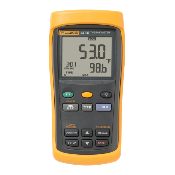
53IIB/54IIB Getting Started Table 3. Components Components Thermocouple T1 input Model 54: Thermocouple T2 input Holster Display Buttons Battery door Batteries aat01f.eps Figure 1. Components... -
Page 10: Display Elements
53IIB/54IIB Users Manual Display Elements Table 4. Display Elements The thermocouple measurement includes an offset. See "Changing Setup Options." The displayed readings do not change. A shift function is in progress. Readings are being logged. Setup is in progress. ... -
Page 11: Buttons
53IIB/54IIB Getting Started Buttons Table 5. Buttons Press to turn the thermometer on or off. Press , (CANCEL) to stop displaying the minimum, maximum, and average readings in the secondary display. (Shift function) Press , (CLEAR MEMORY) to delete logged readings from memory. Press , ... - Page 12 53IIB/54IIB Users Manual Table 5. Buttons (cont.) Press to freeze or unfreeze the displayed readings. Press when turning on the thermometer to test the display. All display elements appear. Model 54: Press to toggle showing the T1, T2, and T1-T2 (differential temperature measurement) in the primary or secondary display.
-
Page 13: Using The Thermometer
53IIB/54IIB Using the Thermometer Entering and Exiting Setup Using the Thermometer When the thermometer is in Setup mode, the display Plug the thermocouple(s) into the input connector(s). shows . Press to turn on the thermometer. Press to start or exit Setup. After 1 second the thermometer displays the first reading. -
Page 14: Changing The Logging Interval
53IIB/54IIB Users Manual Changing the Logging Interval If you selected a user-defined logging interval: The logging interval determines how often the Press or until the display shows thermometer stores logged readings in memory. You hour:min or min:sec, and then press to choose the length of the logging interval. -
Page 15: Changing The Thermocouple Type
53IIB/54IIB Changing Setup Options Changing the Thermocouple Type Changing the Offset Press or until the display shows TYPE. You can adjust the thermometer's readings to compensate for the errors of a specific thermocouple. See "Using the Press to display the thermocouple type choices. Offset to Adjust for Probe Errors."... -
Page 16: Enabling Or Disabling Sleep Mode
53IIB/54IIB Users Manual Enabling or Disabling Sleep Mode Setting the Time The thermometer enters sleep mode if no button press Press or until the display shows the time if it occurs for 20 minutes. is set or shows "- - : - -." Pressing any button wakes the thermometer and returns it Press ... -
Page 17: Changing The Line Frequency
53IIB/54IIB Measuring Temperatures Changing the Line Frequency Measuring Temperatures For optimum rejection of line noise, set the thermometer Connecting a Thermocouple for the local line frequency as follows: Thermocouples are color coded by type based on the Press or until the display shows . North American ANSI Color Code: Press ... -
Page 18: Displaying Temperatures
53IIB/54IIB Users Manual Displaying Temperatures Holding the Displayed Temperatures Press to select the correct temperature scale. Press to freeze the readings on the display. Hold or attach the thermocouple(s) to the The display shows . measurement location. Model 54: Press to toggle showing the T1, T2, or The temperature reading appears in the selected... -
Page 19: Using The Offset To Adjust For Probe Errors
53IIB/54IIB Using Memory Using the Offset to Adjust for Probe Errors Using Memory Use the offset option in Setup to adjust the thermometer's During a logging session the thermometer stores logged readings to compensate for the errors of a specific readings in its memory. -
Page 20: Initial Conditions And Data Entries
53IIB/54IIB Users Manual Initial Conditions and Data Entries Starting and Stopping Logging Logged readings include initial conditions and data entries. Setup, memory clear, and PC communications are inaccessible during logging. The initial conditions are the thermocouple type and the offsets for each thermocouple input. You can only view Set the logging interval. -
Page 21: Clearing Memory
53IIB/54IIB Using Memory Clearing Memory Viewing Logged Readings When memory is full, appears on the display and Press to view logged readings. logging stops. You can clear memory in normal or MIN The display shows . MAX mode. Press ... -
Page 22: Communicating With A Pc
53IIB/54IIB Users Manual Communicating with a PC Press to step through the minimum, maximum, average, and current logged reading. For example, You can transfer the contents of the thermometer’s Figure 4 shows the maximum reading in memory. The memory to a PC using FlukeView Forms. The maximum reading occurred at 1:49 P.M. -
Page 23: Maintenance
Refer to the safety information in Table 1 before replacing thermometer annually, starting one year after purchase. the batteries. To calibrate the thermometer, contact Fluke for the Turn off the thermometer if necessary. Service Center nearest you or follow the calibration procedure in the service manual listed in "Replacement... -
Page 24: Thermocouple (Supplied With Thermometer)
53IIB/54IIB Users Manual 80 PK-1 Thermocouple (supplied with General thermometer) Weight 280 g (10 oz) Type K, Chromel Alumel, bead style Type 2.8 cm 7.8 cm 16.2 cm Dimensions (1.1 in 3 in 6.4 in) C to 260 Temperature (without Range holster) (-40... -
Page 25: Replacement Parts And Accessories
53IIB/54IIB Replacement Parts and Accessories Electrical (cont.) Applicable NIST-175 Standards Measurement J-, K-, T-, E-, and N-type: [0.05 Accuracy is specified for ambient temperatures between 18 Accuracy, T1, T2, reading C (0.5 F)] [below -100 F) and 28 C (82 F) for a period of 1 year. - Page 26 53IIB/54IIB Users Manual...
Need help?
Do you have a question about the 53IIB and is the answer not in the manual?
Questions and answers