Table of Contents
Advertisement
© 2011 JVC KENWOOD Corporation
D-ILA PROJECTOR
PROJECTEUR D-ILA
PROYECTOR D-ILA
DLA-X90R
DLA-X70R
DLA-X30
For Customer use :
Enter below the serial No. which is
located on the side of the cabinet.
Retain this information for future
reference.
Model No. DLA-X70R
Serial No.
0711TTH-AO-AO
ENGLISH FRANÇAIS ESPAÑOL/CASTELLANO
MANUEL D'INSTRUCTIONS
MANUAL DE INSTRUCCIONES
STAND BY
ON
COMPONENT
HDMI 1
HDMI 2
COMP .
ASPECT
ANAMO
INFO.
LENS
CONTROL
LENS AP.
C.M.D
HIDE
LIGHT
MENU
BACK
FILM
CINEMA
OINEMA
ANIME
NATURAL
STAGE
3D
USER1
USER2
USER3
GAMMA
C.TEMP.
C.SPACE
PIC.ADJ.
COLOR COLOR
PICTURE
TEMP.
SPACE ADJUST
90 70
Pour utilisation par le client :
Entrer ci-dessous le N° de série qui
est situé sous le boîtier. Garder
cette information comme référence
pour le futur.
DLA-X90R
DLA-X90R
N° de modèle DLA-X70R
DLA-X30
DLA-X30
N° de série
INSTRUCTIONS
Instrucción para el cliente :
Introduzca a continuación el nº de
serie que aparece en la parte
inferior lateral de la caja. Conserve
esta información como referencia
para uso ulterior.
DLA-X90R
Modelo Nº DLA-X70R
DLA-X30
Nº de serie
PC021082599-1
Advertisement
Table of Contents

Related Manuals for JVC DLA-X30B


Summary of Contents for JVC DLA-X30B
- Page 1 DLA-X90R DLA-X90R DLA-X90R Model No. DLA-X70R N° de modèle DLA-X70R Modelo Nº DLA-X70R DLA-X30 DLA-X30 DLA-X30 Serial No. N° de série © 2011 JVC KENWOOD Corporation Nº de serie 0711TTH-AO-AO PC021082599-1...
-
Page 2: Getting Started
This product has a High Intensity Dis- FCC INFORMATION (U.S.A. only) charge (HID) lamp that contains CAUTION: mercury. Changes or modification not approved by JVC could void the user’s authority to operate the Disposal of these materials may be equipment. regulated in your community due to NOTE: environmental considerations. - Page 3 ENGLISH - All warnings on the product and in the operating - power source indicated on the label. If you are instructions should be adhered to. not sure of the type of power supply to your - All operating instructions should be followed. home, consult your product dealer or local - Place the projector near a wall outlet where the power company.
- Page 4 Be sure to ask your dealer to install the unit please consult your dealer, or the nearest (e.g.attaching it to the ceiling) since special authorized JVC service center. technical knowledge and skills are required - When fixing the unit to the ceiling, Please note that for installation.
-
Page 5: Power Connection
THIS APPARATUS MUST BE EARTHED. Dear Customer, This apparatus is in conformance with the valid European directives and standards regarding electromagnetic compatibility and electrical safety. European representative of JVC KENWOOD Corporation is: JVC Technical Services Europe GmbH Postfach 10 05 04 61145 Friedberg... - Page 6 Getting started ENGLISH Information for Users on Disposal of Old Equipment and Batteries [European Union only] These symbols indicate that equipment with these symbols should not be disposed of as general household waste. If you want to dispose of the product o r battery, please consider the collection systems or fa cilities for appr opriate recycling.
- Page 7 ENGLISH ESPAÑOL / CASTELLANO Información para los usuarios sobre la eliminación de baterías/pilas usadas [Sólo Unión Europea] Estos símbolos indican que el equipo con estos símbolos no debe desecharse con la basura doméstica. Si desea desechar el pro ducto o batería/pila, acuda a los sistemas o centros de recogida para que los reciclen debidamente.
- Page 8 Getting started DANSK Brugerinformation om bortskaffelse af gammelt udstyr og batterier [Kun EU] Disse symboler angiver, at udstyr med disse symboler ikke må bortskaffes som almindeligt husholdningsaffald. Hvis du ønsker at smide dette produkt eller batteri ud, bedes du overveje at bruge indsamlingssystem et eller steder, hvor der kan ske korrekt gen brug.
- Page 9 ENGLISH Сведения для пользователей по утилизации старого оборудования и батарей [только для Европейского союза] Данные символы указывают на то, что оборудование, на которое они нанесены, не должны утилизироваться, как обычные бытовые отходы. При необходимости утилизировать такое изделие или батарею обратитесь в специальный пункт сбора...
- Page 10 Getting started Cрпска Informacije za korisnike o odlaganju stare opreme i baterija [Samo u zemljama gde se primenjuje] Ovi simboli ukazuju da proizvod i baterije sa ovim simbolom ne smeju biti odloženi kao nesortiran kućni otpad. Ako želite da ih se rešite, molimo vas da ne upotrebljavate običnu kantu za đubre.
-
Page 11: Thx Certification
Based on the know-how that we have cultivated over the past 25 years in areas including film production, cinema viewing environment design, and audio/video editing, we have established a partnership with JVC KENWOOD Corporation to develop an unprecedent- ed home theater projector system. - Page 12 Getting started For detail information about ISF, please refer web site 90 70 http://www.imagingscience.com/...
-
Page 13: Table Of Contents
ENGLISH Contents Getting started Masking the Surrounding Area of an Image ..........40 Safety Precautions ......2 Temporary turning-off of the video ..41 THX Certification ....11 90 70 Adjustment of the keystone correction ... 41 Contents .........13 Adjustments and settings Accessories/Optional in the menu ........42 Accessories ........14... -
Page 14: Accessories/Optional Accessories
Getting started Accessories/Optional Accessories Check the Accessories Lens Cover ................1 piece Remote Control ................1 piece AAA size Batteries (for operation confirm)........2 pieces Power Cord For the US market (2 m) .........1 piece Power Cord For the EU market (2 m) .........1 piece Power Cord For the UK market (2 m) .........1 piece ●... -
Page 15: Controls And Features
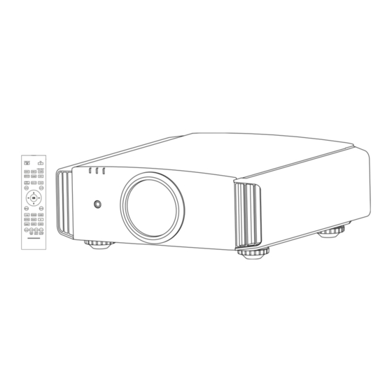
ENGLISH Controls and features Main body - Front ③ Indicator STANDBY/ON LAMP WARNING ④ Exhaust Vent ① Lens ④ Exhaust Vent ② Remote receiver (front) Lens cover ① Lens ③ Indicator Please see “About the indicator display” for This is a projection lens. Please do not look inside during projection. -
Page 16: Main Body - Rear
Getting started Controls and features (continued) Main body - Rear ⑤ Inlets ⑨ Lamp Cover ⑩ Operation panel ⑤ Inlets ⑧ Input terminal ⑪ Light receiving section ⑫ Power input of the remote control (rear) terminal ⑧ Input terminal ⑪ Light receiving section of the There is also a terminal other than the input remote control (rear) terminal for video images, such as those used... -
Page 17: Main Body - About The Indicator Display
ENGLISH Controls and features (continued) Main body - About the indicator display Warnings and indications used during normal operation mode of this unit are displayed with the indicators for [STAND BY / ON], [LAMP], [WARNING] at the front of this unit. Meaning of the lighting figures: The display the indicator lights. -
Page 18: Main Body - Warning Display And Confirmation/Response
Getting started Controls and features (continued) Main body - Warning display and confirmation/response Warning display You are informed of the contents of warning notices by the (repeated) displays of the [WARNING] and [LAMP] indicators. Moreover, the [STAND BY / ON] indicator, which shows the operating mode of the unit, is displayed simultaneously as described above. -
Page 19: Main Body - Input Terminal
RGB (G on Sync) signals, component (Y, Cb, is no such product as an external light receptor. Cr) signals, DTV format (Y, Pb, Pr) signals. It Therefore, please consult your authorized JVC can also be connected with devices, which are KENWOOD Corporation. (Reference page: 33) equipped with signal output, etc. -
Page 20: Remote Control
Getting started Controls and features (continued) Remote Control ■ 90 70 STAND BY To turn off the power To turn on the power This button sequentially switches 3D formats INPUT (Reference page: 63) To select input mode (*) This function cannot be used HDMI 1 HDMI 2 COMP . -
Page 21: How To Insert Batteries Into The Remote Control
ENGLISH Controls and features (continued) ■ Remote Control STAND BY To turn on the power To turn off the power This button sequentially switches INPUT To select input mode 3D formats (Reference page: 63) (Reference page: 36) (*) This function cannot be used HDMI 1 HDMI 2 COMP . -
Page 22: Preparation
Preparation About installation Important points concerning the installation Please read the following carefully before the installation of this unit. Installation environment Please be careful when using CAUTION CAUTION This unit uses a projection lamp, which will get hot when This unit is a precision device. Therefore, please refrain in use. -
Page 23: Installing The Projector And Screen
ENGLISH About installation (Continued) Installing the Projector and Screen While installing, please place this unit and the screen perpendicular to each other. Failing to do so may increase trapezoidal distortion. (Reference page: 36, 52) Set Angle The angle range which can be set for this unit is ±30°. ●... -
Page 24: Fixation Of The Projector
Special expertise and techniques are required for Regardless whether the unit is still under mounting this unit. Be sure to ask your dealer or a guarantee, JVC is not liable for any product specialist to perform mounting. damage caused by mounting the unit with non- ●... -
Page 25: Screen Size And Projection Distance
ENGLISH About installation (Continued) Screen Size and Projection Distance Determine the distance from the lens to the screen to achieve your desired screen size. This unit uses a 2.0x power zoom lens for projection. ■ Relationship Between Projection Screen Size and Projection Distance Projection Screen Size Projection Screen Size Approximate Projection... -
Page 26: About The Connection
Preparation About the connection Types of possible input signals Analog Video Input Format 480i, 480p, 576i, 576p, 720p/50Hz, 720p/60Hz, signals 1080i/50Hz, 1080i/60Hz 480i, 480p, 576i, 576p, 720p/50Hz, 720p/60Hz, Digital Video Input Format 1080i/50Hz, 1080i/60Hz,1080p/24Hz, signals 1080p/50Hz, 1080p/60Hz 720p/50Hz, 720p/60Hz, 1080p/24Hz, 1080i/50Hz, 1080i/60Hz frame pack method 1080i/60Hz, 1080p/60Hz, 1080i/50Hz, 1080p/50Hz, 1080p/24Hz, side by side method... -
Page 27: Types Of Possible Input Signals (Pc Compatible)
ENGLISH About the connection (Continued) Types of possible input signals (PC compatible) ● PC signal (D-sub 3-lines 15 pins) 90 70 Total No. of Total No. No. of dot CLK No. of effective Designation Resolution of dots effective [kHz] [Hz] [MHz] lines dots... -
Page 28: Connection To The Unit
Preparation About the connection (Continued) Connection to the unit ● Do not turn on the power until connection is complete. ● The connection procedures differ according to the device used. For details, refer to the instruction manual of the device to be connected. ●... -
Page 29: Connecting Via Hdmi Cable
ENGLISH About the connection (Continued) Connecting via HDMI Cable ■ This unit Notebook PC STANDBY/ON INPUT HDMI BD/DVD recorder RS-232-C REMOTE TRIGGER SYNCHRO CONTROL MENU BACK HDMI 1 input terminal HDMI 2 input terminal HDMI output terminal HDMI cable (sold separately) If noise is produced, take PCs (Notebook PC) away from this unit. -
Page 30: Connecting Via Component Video Cable
Preparation About the connection (Continued) Connecting via Component Video Cable ■ This unit STANDBY/ON INPUT BD/DVD player MENU BACK HDMI RS-232-C REMOTE TRIGGER SYNCHRO CONTROL To component video input terminals Component video output terminals (red) (blue) Component video cable Y (green) (sold separately) ●... -
Page 31: Connecting Via Pc Cable
ENGLISH About the connection (Continued) Connecting via PC Cable ■ 90 70 This unit STANDBY/ON Notebook PC INPUT HDMI RS-232-C REMOTE TRIGGER SYNCHRO CONTROL MENU BACK To PC input terminal PC cable(sold separately) VGA output terminal For information on supported input signals, please refer to “Specifications”. -
Page 32: Connecting Via Trigger Cable
Preparation About the connection (Continued) Connecting via Trigger Cable ■ This unit STANDBY/ON INPUT Screen HDMI RS-232-C To Trigger output terminal REMOTE TRIGGER SYNCHRO CONTROL MENU BACK Trigger cable (sold separately) Trigger input terminal ( Φ 3.5) CAUTION ● Do not supply the power to the other devices. ●... - Page 33 ENGLISH About the connection (Continued) Connected by LAN terminal ■ This unit connection cable (sold separately) STANDBY/ON INPUT Network HDMI RS-232-C Server REMOTE TRIGGER SYNCHRO CONTROL MENU BACK ● The network is used to control the unit. It is not used for transmission of the video signal. ●...
-
Page 34: Connection Of The Power Cord (Provided)
Preparation About the connection (Continued) Connection of the power cord (provided) Once you have connected the equipment, connect the projector power cord. 1 Connect the power cord supplied with the STANDBY/ON unit power input terminal INPUT HDMI RS-232-C 2 Connect to the power outlet REMOTE TRIGGER SYNCHRO... - Page 35 ENGLISH MEMO...
-
Page 36: Operation
Operation Basic Operation Basic operation procedures Once you have finished the basic setup, the unit can normally be used just with the following operations. Turn on power source STAND BY INPUT STANDBY/ON HDMI 1 HDMI 2 COMP . Light on (Green) FORMAT SETTING ●... - Page 37 ENGLISH Adjust the shift (image position) Lens Control MEMO LENS Shift About Cool Down Adjust accordingly mode Select Back Operate BACK by pressing the up/down/left/right ● The Cool Down mode is a buttons function to cool down the lamp ● After adjusting the image position, it may be necessary to for approximately 60 seconds select “Pixel Adjust”...
-
Page 38: Frequently Used Useful Functions
Operation Basic Operation (continued) Frequently used useful functions You can change the screen size of the projected image or hide the surrounding area of an image for which quality at the outer area has deteriorated. STAND BY Setting the Screen Size Masking the Surrounding Area of an Image Temporary turning-off of the video INPUT... - Page 39 ENGLISH Set a Aspect value ① Select Input Signal HDMI COMP. PC Picture Position Aspect (Video) 16:9 Mask ② Confirm 16:9 Progressive Auto Custom 3D Setting Operate Exit Back MENU Select BACK Example: When the “Aspect” value is To end changed from “4:3”...
-
Page 40: Masking The Surrounding Area Of An Image
Operation Masking the Surrounding Area of an Image Images for which quality at the outer area has deteriorated MEMO can be projected by masking (hiding) the surrounding area of the projected image. ● Masking is available only Project the image when high definition images are input. -
Page 41: Temporary Turning-Off Of The Video
ENGLISH Basic Operation (continued) Temporary turning-off of the video You can hide the image temporarily. HIDE STAND BY Green light blinks when the image is hidden. INPUT ● Press the button again to display image. HIDE HDMI 1 HDMI 2 COMP . -
Page 42: Adjustments And Settings In The Menu
Operation Adjustments and settings in the menu Structure of the menu hierarchy (summary) The Menu of this unit is organized as follows. As this is only a brief guideline, items, which might not be displayed due to certain settings, are still displayed in the illustration. Moreover, in regard to , it shows countermeasures for all kinds of devices, but there the values for setting and adjustment might be different. - Page 43 ENGLISH Adjustments and settings in the menu (continued) [1-2] Advanced 90 70 Picture Adjust Picture Adjust Advanced Advanced > > [1-2-1] [1-2-1] Sharpness Sharpness [1-2-2] Color Space Custom Gamma Standard [1-2-2] [1-2-3] Custom Gamma Color Management User Name Edit User Name Edit Clear Motion Drive Clear Motion Drive CMD Demo...
- Page 44 Operation Adjustments and settings in the menu (continued) [1-2-2] Custom Gamma Picture Adjust Custom Gamma >> Correction Value Custom1 Normal 1023 White Custom2 P. 58 Custom3 Green Blue Reset 100(%) Exit Operate Back MENU BACK Select [1-2-3] Color Management Picture Adjust Color Management >>...
- Page 45 ENGLISH Adjustments and settings in the menu (continued) [2] Input Signal When inputting 2D signals When inputting 2D signals Input Signal Input Signal [2-1] [2-1] HDMI HDMI COMP. COMP. [2-2] Picture Position PC Picture Position Aspect(Video) 16:9 Mask Aspect(Video) 16:9 Progressive Mask Auto...
- Page 46 Operation Adjustments and settings in the menu (continued) [2-2] PC Input Signal Auto Alignment P. 62 Tracking Phase Picture Position Operate Exit Back MENU BACK Select [2-3] 3D Setting Input Signal 3D Setting 3D Format Auto 2D/3D Parallax P. 63 Crosstalk Cancel ...
- Page 47 ENGLISH Adjustments and settings in the menu (continued) [3] Installation Installation [3-1] Lens Control [3-2] Pixel Adjust Installation Style Front Keystone P. 64 Anamorphic Screen Adjust Black Level Operate Exit Back BACK MENU Select [3-1] Lens Control Installation Installation Lens Control Lens Control Focus Focus...
- Page 48 Operation Adjustments and settings in the menu (continued) [4] Display Setup Display Setup Back Color Black Menu Position Menu Display Line Display P. 71 5sec Source Display Logo Language English Operate Exit Back MENU BACK Select [5] Function Function Trigger Off Timer High Altitude Mode Remote Code...
- Page 49 ENGLISH Adjustments and settings in the menu (continued) [6] Information When inputting HDMI signals Information Input HDMI-2 : Source 1080p60 : P. 73 Deep Color : 8bit Lamp Time : 160H Soft Ver. : 12.011 Operate Exit Back MENU BACK Select When inputting PC signals 90 70...
-
Page 50: Menu Operation Button
Operation Adjustments and settings in the menu (continued) Menu operation button Operate the menu by use of the buttons on the main body or the remote control. Button Function This unit Remote Control MENU Menu is displayed. MENU STANDBY/ON While the menu is displayed, the menu screen is turned off. -
Page 51: Menu Operation Procedure
ENGLISH Adjustments and settings in the menu (continued) Menu operation procedure 1 Press MENU. The main menu is displayed on the screen. The submenu items, which are currently selected, are shown. Currently selected menu Picture Adjust items are highlighted and the icon is colored Picture Mode Natural Color Profile... -
Page 52: Menu Item Description
Operation Adjustments and settings in the menu (continued) Menu item description All numbers for the items within [ ]are default settings. It is possible to operate all items displayed in the menu display by pressing OK/BACK or the cursor (up, ●... - Page 53 This is the most suitable profile when using 3D-glasses. It is a mode that does not adjust the color management. Custom 1 You can install the color profile supplied by this JVC. The name changes after Custom 2 installation. Custom 3...
- Page 54 Operation Adjustments and settings in the menu (continued) Color Temp. It is possible to set the color temp. To "[1-1] Color Temp." of the submenu Gamma It is possible to set the gamma curve. Please set to your preference. Settings: Normal, A (3D), B (3D), Film 1, Film 2, Film 3 Film 4, A, B, C, D, Custom 1, Custom 2, Custom 3 [Normal] Typically we recommend this setting.
- Page 55 ENGLISH Adjustments and settings in the menu (continued) [1-1] Color Temp. Use this function to se the video image color temperature. Adjust according to Color Temp. > your preference. 6500K Preset Gain Red Custom1 Gain Green (*) The settings available will vary depending on the "Picture Mode". However, Custom2 Gain Blue Custom3...
- Page 56 Operation Adjustments and settings in the menu (continued) [1-2] Advanced Use this function to set video image contours, overall sharpness, noise Advanced > reduction mode and video afterimage. You can also create your preferred Sharpness gamma and color quality. Custom Gamma Use the UP and DOWN keys to select items.
- Page 57 ENGLISH Adjustments and settings in the menu (continued) Picture Adjust User Name Edit >> Name User 1 Input cursor Select cursor Character list " & < > SPACE Clear All Clear Operate Exit Back MENU Select BACK Clear Motion Drive It improves video images with fast movements to produce clear video images with little residual image retention.
- Page 58 Operation Adjustments and settings in the menu (continued) [1-2-1] Sharpness Use this function to set video image contours and overall sharpness Sharpness >> according to your preference. Sharpness Detail Enhance Use the UP and DOWN keys to select items. Press the [BACK] key to return to the previous screen.
- Page 59 ENGLISH Adjustments and settings in the menu (continued) Picture Adjust Custom Gamma >> Correction Value Custom1 Normal 1023 White Custom2 Custom3 Green Gamma curve Blue Gradation diagram Reset corresponding Gradation at the 100(%) to the gamma selected point. curve. Exit Operate Back MENU...
- Page 60 Operation Adjustments and settings in the menu (continued) [2] Input Signal Use this function to set the appropriate specifications for the video image HDMI signals input from HDMI, COMP and PC. Set the aspect ratio and screen COMP. mask. PC Picture Position Use the UP and DOWN keys to select items.
- Page 61 ENGLISH Adjustments and settings in the menu (continued) Mask It hides the upper, lower, left and right borders of the screen with a black mask. Can be individually adjusted vertically and horizontally. Please adjust to your preference. (*) When there is a 3D input signal, adjustment is not possible. Settings: Off, 2.5%, 5%, Custom [Off] Not masked.
- Page 62 Operation Adjustments and settings in the menu (continued) Level Check You can confirm the dynamic range of the input signal.A pattern as shown in the illustration is displayed in the four corners and center of the screen. Please compare the dynamic range of input signal with this pattern illustration and confirm.
- Page 63 ENGLISH Adjustments and settings in the menu (continued) [2-3] 3D Setting Use this function to select the 3D signal mode, turn 2D/3D conversion 3D Setting ON/OFF and to adjust the appearance for 3D video images. 3D Format Auto Use the UP/DOWN keys to select an adjustment item. Press the 2D/3D ...
- Page 64 Operation Adjustments and settings in the menu (continued) [3] Installation Use this function to set and adjust installation method and projection Lens Control environment. Pixel Adjust Use the UP/DOWN keys to select an adjustment item. Press the [BACK] Installation Style Front Keystone key to return to the previous screen.
- Page 65 ENGLISH Adjustments and settings in the menu (continued) [3-1] Lens Control Use this function to adjust focus, zoom and shift. You can also turn image Lens Control pattern display ON or OFF and save lens position settings during adjustment. Focus Zoom ...
- Page 66 Operation Adjustments and settings in the menu (continued) Clear Use this function to delete a character. Move the select cursor to the desired location and press the [OK] key on the main unit or on the remote control. This will delete the character to the left of the input cursor in the Name field.
- Page 67 ENGLISH Adjustments and settings in the menu (continued) Adjust Color Use this function to set the color of the pixels you want to adjust. Settings: Red, Blue [Red] Adjust Pattern Color Use this function to set the adjust pattern color. Set according to your preference. Settings: White, Green + (Adjust Color) [White] White...
- Page 68 Operation Adjustments and settings in the menu (continued) See Pixel Adjust Flow and Operation: Adjust(Pixel) Use this function to make general adjustments in the slight color errors in the horizontal/vertical directions of the video images. Select [Adjust Area] to [Whole] and select [Adjust Color] and [Adjust Pattern]. Move the cursor to [Adjust(Pixel)], then press the [OK] Button on the remote control to display the adjust pattern and adjust (pixel) window on the screen.
- Page 69 ENGLISH Adjustments and settings in the menu (continued) See Pixel Adjust Flow and Operation: Adjust(Fine) After making overall adjustment for error across the entire screen, proceed to fine-tuning. Press the [COLOR TEMP] button on the remote control to display the [Adjust(Fine) Window]. Also, from the main menu, set the [Adjust Area] to [All] and select [Adjust Color] and [Adjust Pattern], then move the cursor to [Adjust (Fine)] and press the [OK] button on the remote control to display the adjust pattern and the fine tune window.
- Page 70 Operation Adjustments and settings in the menu (continued) See Pixel Adjust Flow and Operation: Zone Adjust After making overall adjustment for error across the entire screen, proceed to fine-tuning. The screen can be divided vertically and horizontally into 10 sections to make adjustments. Press the [PIC ADJ] button on the remote control to display the [Zone Adjust Window].
- Page 71 ENGLISH Adjustments and settings in the menu (continued) [4] Display Setup Use this function to turn the messages that appear on each screen ON or Back Color Black OFF and to set the background color when there is no signal. Menu Position Use the UP/DOWN keys to select an adjustment item.
- Page 72 Operation Adjustments and settings in the menu (continued) [5] Function Use this function to set command communications, remote control codes, Trigger OFF timer function, etc. You can also reset the lamp time. Off Timer Use the UP/DOWN keys to select an adjustment item. High Altitude Mode Press the [BACK] key to return to the previous screen.
- Page 73 ENGLISH Adjustments and settings in the menu (continued) [5-1] Network Use this function to configure the network settings used for Network command communication. DHCP Client IP Address 192. 168. 0. 2 Use the UP and DOWN keys to select items. Press the [BACK] Subnet Mask 255.
-
Page 74: Operation Guide (Glossary)
Operation Operation guide (glossary) Gamma Curve The description of the gamma curve that assumes a gamma curve unit. Please read the relevant detailed description and professional books. The gamma curve of the projector to the input video signal determines for each color the relative value of its light output. 100% The value of the input video image signal is displayed as a percentage - with both being displayed in % as units - of the maximum light input signal for bright-... - Page 75 ENGLISH Description of the 3D method This is a description for the 3D-method using this unit, 3D-glasses (sold separately: PK-AG1-B/PK-AG2- B) and an 3D synchro emitter (sold separately: PK-EM1). Set the 3D TV and 3D compatibility software to an appropriate viewing standard. For viewing, a separate unit compatible with 3D playback is needed.
- Page 76 Operation Separate images which can be seen by the right eye and left eye, respectively, are taken and produced separately. Therefore, the image for the left eye is only visible to the left eye, and the images for the right eye only or the right eye.
- Page 77 ENGLISH The frame sequential method is a way of displaying video images left and right sequentially. The projector projects the video images used for the left- and right eyes onto the screen. The video images for the left and right side are only visible with the respective eye, as the left and right side of the 3D glasses are opened and shut by a liquid crystal shutter.
-
Page 78: Maintenance
Maintenance Replacing the Lamp The lamp is a consumable item. If the image is dark or the lamp is turned off, replace the lamp unit. When the lamp replacement time approaches, a message is displayed on the screen and the condition ●... - Page 79 ENGLISH Install the new lamp unit CAUTION ● Use only genuine replacement parts for the lamp unit. Also, never attempt to reuse an old lamp unit. This may cause a malfunction. ● Do not touch the surface of a new lamp. This may shorten the lamp life and cause lamp blowout.
-
Page 80: Resetting Lamp Time
Maintenance Replacing the Lamp (Continued) Resetting lamp Time After replacing a new lamp unit, please reset the lamp time. STAND BY Description of two methods. INPUT Reset the lamp time from the menu screen. HDMI 1 HDMI 2 COMP . SETTING FORMAT Display the setting menu... - Page 81 ENGLISH Reset the lamp time by remote control. STAND BY Insert the power plug to the power INPUT outlet HDMI 1 HDMI 2 COMP . FORMAT SETTING Red Lights LENS. LENS ANAMO. CONTROL MEMORY Must operate with the remote HIDE LIGHT control in the standby mode (the projector is powered, but is not...
-
Page 82: Method For Cleaning And Replacing Filters
Maintenance Method for cleaning and replacing filters Clean the filter regularly or air intake efficiency may deteriorate and malfunction may occur. Remove the inner filter. CAUTION ● Pull the power plug from the power outlet. ● Please turn this unit and if you put in on a bed or a table, first place something soft Lift up while pushing the claw... - Page 83 ENGLISH MEMO...
-
Page 84: Others
Others Troubleshooting Before sending the unit to your authorized dealer for repair, please check the following points. The following situations are not malfunctions. ■ You do not need to worry about the following situations if there is no abnormality on the screen. - Page 85 ENGLISH The picture cannot be projected Will the picture flicker and Reference page: become invisible with HDMI Please use a short HDMI cable. input? The image cannot output by HDMI terminal Is the setup of “Control with Reference page: Set up the “Control with HDMI” function to “Off”. HDMI”...
-
Page 86: In Case This Message Is Displayed
Others In case this message is displayed Message Cause (Details) No device is connected to the input terminal. COMP The input terminal is connected but there is no signal. NO Input Input the video signals. A video signal that cannot be used in this unit has been input. COMP. -
Page 87: Rs-232C Interface
ENGLISH RS-232C Interface It is possible to control this machine, if it is connected by an RS-232C cross cable (D-Sub9 pin) to a PC. Otherwise, this machine can be controlled via a computer network by connecting it with a LAN cable and sending of control commands. Please use it after you have understood this by reading professional books, or by discussing it with a system administrator. -
Page 88: Command Format
Others RS-232C Interface (Continued) Command Format The command between this unit and the computer consists of “Header” , “Unit ID” , “Command” , “Data” and “End”. ● Header (1 byte), Unit ID (2 bytes), Command (2 bytes), Data (n bytes), End (1 byte) ■... - Page 89 ENGLISH Reference command and data (Binary code) Command Type Data description During standby or power on 30: Standby mode 5057 Power supply 31: Power-on mode 32: During Cool Down mode 34: Warning mode During power on 32: COMP. 90 70 4950 Input 32: PC...
-
Page 90: Rs-232C Communication Examples
Others RS-232C Interface (Continued) RS-232C Communication Examples This section shows the communication examples of RS-232C. ■ Operating command Type Command Description Connection PC→This unit: 21 89 01 00 00 0A Connection check. check This unit→PC: 06 89 01 00 00 0A PC→This unit: 21 89 01 50 57 31 0A When power is turned on from Power (On) -
Page 91: Copyright And Caution
ENGLISH Copyright and Caution About Trademarks and Copyright ● HDMI, HDMI logo and high definition multimedia interface are trademarks or registered trademarks of HDMI Licensing LCC. Caution Maintenance Procedures D-ILA Device Characteristics Do not project still pictures or pictures that have still Dirt on the cabinet segments for a long period of time. -
Page 92: Specifications
Others Specifications Product Name D-ILA Projector Model Name DLA-X90R-B,DLA-X70R-B,DLA-X30-B,DLA-X30-W D-ILA device * 2 * 3 Display Panel/Size 0.7" (1920pixels x 1080pixels) x 3 (Total no. of pixels: Approx. 6.22million) 2.0 x power zoom lens (1.4:1 to 2.8:1) Projection Lens (Zoom/Focus: Power) 220 W Ultra-high pressure mercury lamp [Part No.: PK-L2210U] Light-source Lamp Average lifespan: 3000 hours (normal mode) - Page 93 ENGLISH * 1 Regarding -W the color of the main body is some kind of white color. Regarding –B, the color of the main body is some kind of black. * 2 D-ILA is the abbreviation for Direct drive Image Light Amplifier. * 3 D-ILA devices are manufactured using extremely high-precision technology.
-
Page 94: Dimensions
Others Dimensions (Unit: mm) Top Surface Bottom Surface Lens Lens Front Back Surface 227.5 Φ60 Lens center Lamp cover Connection terminal section of the illustration is . 90 70... -
Page 95: Index
ENGLISH Index [4] Display Setup ....... Page 48 Shorthand for "Three-dimensional" [5] Function ........Page 48 Operation Guide (Glossary) ....Page 74 [6] Information ........Page 49 Connection by 3D SYNCHRO Operating procedure ......Page 51 terminal ..........Page 31 Batteries 3D format of [2-3] 3D Setting ..... - Page 96 Others Index (continued) Message Indicator (LED) display....... Page 17 Meaning ..........Page 86 Lamp Replacement Lamp Number ....Page 78 Recommended use time ....Page 78 Lamp time of [6] Information ....Page 73 Replacement ........Page 78 Lamp power of [1-2] Advanced ..Page 57 Lamp reset of [5] Function ....
Need help?
Do you have a question about the DLA-X30B and is the answer not in the manual?
Questions and answers