Advertisement
Table of Contents
- 1 Fuel Selection
- 2 Radio Operation
- 3 First Aid
- 4 Preparing the Radio
- 5 Charging the Receiver Batteries
- 6 Operating Radio - Steering Function
- 7 Operating Radio - Throttle/Brake Function
- 8 Adjusting Throttle/Brake Linkage
- 9 Adjusting the Carburetor
- 10 Preparing the Engine
- 11 Starting the Engine
- 12 Engine Break-In
- 13 Operation Tips
- 14 Troubleshooting
- Download this manual
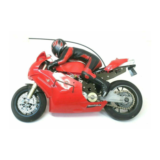
1/5 SCALE DUCATI 999R NITRO POWERED R/C MOTORBIKE
NO.6301-F
Official Product under license of Ducati Motor Holding S.p.A.
Please ensure you read and fully understand all the instructions before operation.
The contents are subject to change without prior notice due to product improvements and specification changes.
INSTRUCTION MANUAL
WARRANTY
Thunder Tiger Corporation guarantees this model kit to be free from defects in both material and workmanship.
The total monetary value under warranty will in no case exceed the cost of the original kit purchased. This warranty
does not cover any components damaged by use or modification. Part or parts missing from this kit must be
reported within 60 days of purchase. No part or parts will be sent under warranty without proof of purchase. To
receive part or parts under warranty, the service center must receive a proof of purchase and/or the defective part
or parts. Should you find a defective or missing part, contact the authorized Thunder Tiger Service/Distributor
nearest you. Under no circumstances can a dealer or distributor accept return of a kit if assembly has started.
Advertisement
Table of Contents

Related Manuals for THUNDER TIGER 999R


Summary of Contents for THUNDER TIGER 999R
- Page 1 1/5 SCALE DUCATI 999R NITRO POWERED R/C MOTORBIKE NO.6301-F Official Product under license of Ducati Motor Holding S.p.A. Please ensure you read and fully understand all the instructions before operation. The contents are subject to change without prior notice due to product improvements and specification changes.
- Page 2 CAUTION Thank you for purchasing a Thunder Tiger Product. Please read all instructions and familiarize yourself with the products and controls before operation. 1. This product is not a toy. It is a high performance model product. It is important to familiarize yourself with the model, its manual, and its construction before assembly or operation.
-
Page 3: Fuel Selection
IMPORTANT NOTES AND WARNING FUEL SELECTION 1. Choose a fuel from a reputable, brand name company that is approved for car/truck use. Do not use airplane or boat fuels in your car/truck. Choose methanol based model engine glow fuel that has a nitro content in the range 10%-30% and 5% to 18% caster/synthetic oil content for lubrication. - Page 4 INSTALLING THE RADIO GEAR Skip if already assembled in RTR version a. Install the receiver switch onto the servo mount beside the steering servo with 2 tap screws. b. Install the steering servo onto the servo mount with four tap screws. (Note the output shaft should be centered between the chassis frames.) c.
- Page 5 INSTALLING STEERING SERVO LINKAGE Skip if already assembled in RTR version 109 mm 13 mm a. Build the oil-filled steering damper & servo linkage as shown on the diagram. The initial factory setting of the steering servo linkage (with damper) is 109mm without pressing or extending between each two ends.
- Page 6 INSTALLING THROTTLE/BRAKE LINKAGE Skip if already assembled in RTR version a. Build the throttle/brake linkages as shown in the diagram. b. Install the kinked linkage end onto the carburetor lever, and secure the disc brake wire onto the pivoting linkage collar with 1.5mm set screw. c.
- Page 7 INSTALLING THE SIDE GUARD WIRE AND ADJUSTING THE STABILITY a. Use a hex driver to loosen the screws of the mount on the side of the body frames. b. Install the supplied side guard wire into the mounts and re tighten the screws.. c.
-
Page 8: Preparing The Radio
CHARGING THE GLOW PLUG STARTER a. Plug the charger into an AC outlet, and then pull on the igniter lever to accept the charging adapter. b. At this point, the small red LED indicator on the charger should light up indicating the charging sequence is in progress. -
Page 9: Charging The Receiver Batteries
CHARGING THE RECEIVER BATTERIES The RX battery pack and charger must be purchased seperately The RX battery pack must be fully charged before running the motorbike. For best results, let the RX battery pack cool before charging. Heat may prevent the batteries from charging to full capacity and also decreases the performance of the batteries. -
Page 10: Operating Radio - Throttle/Brake Function
OPERATING RADIO - THROTTLE/BRAKE FUNCTION about 1mm about 1mm a. Check the radio throttle/brake functions. With the radio transmitter and receiver on, pull the trigger/push the stick forward. The carburetor should be fully opened and the brake disengaged. To check the brake is not engaged, simply spin the wheel whilst pulling the trigger/pushing the stick forward. -
Page 11: Adjusting Throttle/Brake Linkage
ADJUSTING THROTTLE/BRAKE LINKAGE The DUCATI 999R GP motorbike is equipped with a rear disc brake that bolts on between the rear wheel and the rear swing arm. The rear brake system is preset at the factory. As the brake material wears, you may need to replace the brake pad (see spares list) and future adjustments may be necessary. -
Page 12: Adjusting The Carburetor
ADJUSTING THE CARBURETOR a. Idle adjustment screw: To set the carburetor idle (smaller needle sticking out from the carburetor body), you can remove the lower body or just insert a 0.5mm/1/8inch Flat-head screwdriver from the opened front end to turn the screw as pictured. Initial idle setting should leave 1mm carburetor gap. - Page 13 FUELLING a. Squeeze the air out of the bottle, then insert the fuel tubing into fuel container and draw fuel into the fuel bottle. The fuel used should be methanol based model engine glow fuel (available at hobby shops) with 10% to 20% nitro content and 5% to 18% caster/synthetic oil content for lubrication.
-
Page 14: Preparing The Engine
PREPARING THE ENGINE a. To start an engine, remove the red glow plug wire, then use the supplied glow plug wrench to remove the glow plug and gasket from the engine. b. Check the glow plug by plugging it into the glow plug igniter. The glow plug element should light up brightly. -
Page 15: Engine Break-In
ENGINE BREAK-IN For a new engine (break-in setting), the high speed needle needs to be set as rich as possible. Turn the high speed needle 1/4 turn counterclockwise from initial setting (2.5 turns from fully closed). Repeat step 17b. Keep doing this until the engine stalls at full throttle, then turn the high speed needle 1/4 turn clockwise. -
Page 16: Troubleshooting
TROUBLESHOOTING Description Cause Solution Engine does not start 1. Fuel tank is empty 1.Add fuel the bike 2. Contaminated fuel 2.Replace with new fuel 3. Glow plug does not work 3.Replace the glowplug and see Step15 "PREPARING THE ENGINE" section. 4.
Need help?
Do you have a question about the 999R and is the answer not in the manual?
Questions and answers