Table of Contents
Advertisement
Advertisement
Table of Contents

Related Manuals for Marantz Professional PMD520


Summary of Contents for Marantz Professional PMD520
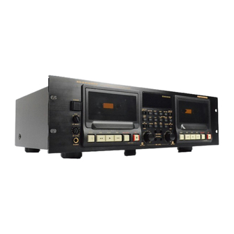
- Page 1 Model PMD520 User Guide 3-Head Double Cassette Deck...
- Page 2 CAUTION RISK OF ELECTRIC SHOCK DO NOT OPEN CAUTION: TO REDUCE THE RISK OF ELECTRIC SHOCK, DO NOT REMOVE COVER (OR BACK) NO USER-SERVICEABLE PARTS INSIDE REFER SERVICING TO QUALIFIED SERVICE PERSONNEL The lightning flash with arrowhead symbol, within an equilateral triangle, is intended to alert the user to the presence of uninsulated “dangerous voltage”...
- Page 3 SAFETY INSTRUCTIONS READ BEFORE OPERATING EQUIPMENT This product was designed and manufactured to meet strict 12. Grounding or Polarization — The precautions that should quality and safety standards. There are, however, some in- be taken so that the grounding or polarization means of an stallation and operation precautions which you should be par- appliance is not defeated.
- Page 4 FIG. 1 EXAMPLE OF ANTENNA GROUNDING ACCORDING TO NATIONAL ELECTRICAL CODE INSTRUCTIONS CONTAINED IN ARTICLE 810 - “RADIO AND TELEVISION EQUIPMENT” ANTENNA LEAD IN WIRE GROUND CLAMP ANTENNA DISCHARGE UNIT (NEC SECTION 810–20) ELECTRIC GROUNDING CONDUCTORS SERVICE (NEC SECTION 810–21) EQUIPMENT GROUND CLAMPS POWER SERVICE GROUNDING...
- Page 5 Dolby noise reduction and HX Pro headroom extension are manufactured under license from Dolby Laboratories Licensing Corporation. HX Pro originated by Bang & Olufsen. “DOLBY” the double-D symbol and “HX PRO” are trademarks of Dolby Laboratories Licensing Corporation. is a registered trademark. Printed in Japan 98 / 10 MIT 418S851252...
-
Page 6: Table Of Contents
TABLE OF CONTENTS Page INTRODUCTION ................................6 PRECAUTIONS ................................6 FEATURES ..................................6 REAR PANEL CONNECTIONS ............................7 FRONT PANEL FEATURES ............................7 DISPLAYS ..................................9 OPERATION ................................. 10 PLAYBACK ................................10 PLAYBACK ON ONE WELL (Same procedure for Well A or Well B) OR BOTH WELLS ........10 CONTINUOUS PLAYBACK .......................... -
Page 7: Introduction
INTRODUCTION MULTIPLE UNITS By connecting several PMD520s in series by way of the cas- Thank you for selecting the Marantz Model PMD520 3-head In- cade connection, multiple units can play or record continu- dependent Dual Well Cassette Deck. ously for logging and other long-time recording applications. -
Page 8: Rear Panel Connections
CONTROL I/O Pin assign REAR PANEL CONNECTIONS Pin No. Function Pin No. Function A A A A A DECK A/B LINE INPUT REW A IN NORM IN These jacks should be connected to LINE OUTPUT of your REW B IN HIGH IN source. - Page 9 r r r r r i i i i i COUNTER BUTTONS TAPE SPEED BUTTONS These switches determine the playback/recording speed of ¡ TAPE TIME tapes in both Wells A and B. This button changes the reference time of tape (tape type) so that the time counter can show accurate time informa- ¡...
-
Page 10: Displays
!3 !3 !3 !3 !3 DISPLAYS TIMER This switch is used to set the timer operation mode. a a a a a TAPE TIME COUNTERS ¡ OFF No timer operation is used when the switch is set to this These counters display the tape position for each Well in position. -
Page 11: Operation
RECORDING OPERATION SINGLE WELL RECORDING PLAYBACK (Same procedure for Well A or Well B) PLAYBACK ON ONE WELL (Same procedure for Well 1. Insert a blank cassette into the cassette holder(s). A or Well B) OR BOTH WELLS 2. Reset the tape counter by pressing the RESET button. 1. -
Page 12: Continuous Recording
TIMER RECORDING CONTINUOUS RECORDING (Same procedure for Wells A and B) 1. Insert blank cassettes into both Wells. Be sure that both decks 1. Connect the power cord of this unit to a timer. are rewound. 2. Insert a blank cassette in the cassette holder(s). 2. -
Page 13: Cascade Operation
SYNCHRONOUS RECORDING Synchronous Recording is possible only when this unit is con- Refer to Fig. 5 nected with a Marantz Professional product equipped with the CASCADE CONTINUOUS PLAYBACK Sync Recording function. The Synchronous Recording connection consists of a single RCA 1. -
Page 14: Other Operations
OTHER OPERATIONS Error Message If a problem occurs during the AUTOMATIC BIAS routine, Caution: an Error message will appear on the display. Please refer ¡ If you must stop playback or recording in the middle of a tape, to the following table. be sure to press the STOP button first, then turn the power off. -
Page 15: Duplication Synchronization
DUPLICATION SYNCHRONIZATION HIGH SPEED DUPLICATION Refer to Fig. 6 1. Insert the master tape in Well A of unit #1. CONNECTION 2. Insert the blank cassettes in both Wells A and B of units #2 and after. 1. Connect the WRC220 * to the RC-5 IN jack of unit #1. 3. -
Page 16: Auto Bias & Eq System
Medium-frequency gain AUTO BIAS & EQ SYSTEM The internal oscillator outputs a 3 kHz signal in the range of ± 4 dB. This signal is recorded and played to adjust the recording System Operation Description gain at around 3 kHz so that the playback output becomes the This system sets the recording bias, recording gain, medium- standard level as shown by B in Figure 3. -
Page 17: Care And Maintenance
Only the most competent and qualified technicians should be This section describes the care and maintenance tasks that allowed to service your unit. Marantz and its factory trained must be performed to optimize the operation of your Marantz warranty station personnel have the knowledge and special equipment. -
Page 18: Technical Specifications
RC-5 Command Table TECHNICAL SPECIFICATIONS Command RC-5 Code 1800 Track System ........... 4 Track, 2 Channel 1801 Head System 1802 Rec Play Head ........Hard Permalloy 1803 Erase Head ........... Dual Gap Ferrite 1804 Approx Head Life ..........1000H 1805 Recording/Erasure System ...... - Page 19 Figure 4 MODEL NO. PMD520 AC120V 60Hz 0.25A LOOP MADE IN JAPAN THROUGH DECK B DECK A REMOTE A OUT LINE LINE RC-5 CONTROL I / O INPUT SELECT FILTER A. B A FULLY INDEPENDENT DOUBLE CASETTE DECK PMD520 DOLBY B–C NR HX PRO 0 3 +6dB 0 3 +6dB POWER...
- Page 20 CASCADE OPERATION Figure 5 IN 1 IN 2 IN 3 MIXER MODEL NO. PMD520 AC120V 60Hz 0.25A LOOP M A D E I N J A P A N THROUGH DECK B DECK A REMOTE A OUT LINE LINE RC-5 C O N T R O L I / O INPUT SELECT...
- Page 21 DUPLICATION SYNCHRONIZATION WRC220 Figure 6 TAPE A TAPE B AUTO TAPE A TAPE B AUTO PREV NEXT BIAS PLAY STOP NORMAL HIGH RECORD RECORD AUTO SPEED SPEED RECORD MUTE BIAS UNIT #1 MODEL NO. PMD520 AC120V 60Hz 0.25A LOOP M A D E I N J A P A N THROUGH DECK B DECK A...
- Page 22 Metal tape detection hole High tape detection hole Figure 7 Figure 8 Figure 9 Be sure to close the casette holder cover when the unit is not to be used for a long period of time. Figure 10...
Need help?
Do you have a question about the Professional PMD520 and is the answer not in the manual?
Questions and answers