Table of Contents
Advertisement
Quick Links
Service
Manual
SECTION
1. TECHNICAL SPECIFICATIONS ................................................................................................................ 1
2. BLOCK DIAGRAM ...................................................................................................................................... 2
3. WIRING DIAGRAM AND ADJUSTMENT POINTS .................................................................................... 3
4. SCHEMATIC DIAGRAM AND PARTS LOCATION (Pattern Side) ............................................................. 5
5. EXPLODED VIEW AND PARTS LIST ...................................................................................................... 15
6. DISASSEMBLY ........................................................................................................................................ 20
7. TEST EQUIPMENT REQUIRED FOR SERVICING ................................................................................. 21
8. ELECTRICAL ADJUSTMENTS ................................................................................................................ 22
9. MICROPROCESSOR AND IC DATA ....................................................................................................... 27
10. ELECTRICAL PARTS LIST ...................................................................................................................... 28
11. XLR511PMD Kit ........................................................................................................................................ 37
Please use this service manual with referring to the user guide (D.F.U) without fail.
Printed in Japan
All manuals and user guides at all-guides.com
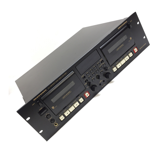
Fully Independent Double Cassette Deck
FULLY INDEPENDENT DOUBLE CASETTE DECK PMD511
EJECT
L
-
R
POWER
DOLBY NR
OFF B C
MEMO
A+B
CONT.
A
B
CASCADE
/CD SYNC
HP SELECT
PITCH
PLAY
STOP
PLAY
REC
5
4
3
HP LEVEL
2
1
0
HEADPHONE
TABLE OF CONTENTS
model PMD511
L
20
15
10
6
3
0 3 +6dB
-
20
15
10
6
3
0 3 +6dB
R
DOLBY NR
RESET
RESET
MEMO
OFF B C
TAPE SPEED
QMS
A+B
HIGH
NORM
MIC MIX
LEVEL
ALC (LINE)
PITCH
0
10
5
PLAY
STOP
PLAY
6
4
6
7
3
7
REC
BALANCE
8
2
8
9
1
9
10
0
10
PMD511 /
PMD511 U,F
EJECT
REC
DOLBY B C NR HX PRO
PAGE
479T855010 AO
3120 785 22230
First lssue 1999.11
N1B
Advertisement
Table of Contents

Related Manuals for Marantz PMD511


Summary of Contents for Marantz PMD511
-
Page 1: Table Of Contents
All manuals and user guides at all-guides.com Service PMD511 / PMD511 U,F Manual Fully Independent Double Cassette Deck FULLY INDEPENDENT DOUBLE CASETTE DECK PMD511 EJECT EJECT 0 3 +6dB 0 3 +6dB POWER DOLBY NR DOLBY NR OFF B C... - Page 2 MARANTZ Parts for your equipment are generally available to our National Marantz Subsidiary or Agent. ORDERING PARTS : Parts can be ordered either by mail or by Fax.. In both cases, the correct part number has to be specified.
-
Page 3: Technical Specifications
All manuals and user guides at all-guides.com 1. TECHNICAL SPECIFICATIONS 2. BLOCK DIAGRAM Track System .......... 4 Track, 2 Channel Head System L/MONO MIX LEVEL Rec Play Head ........Hard Permalloy OUTPUT SELECT AT CONT. MODE DECK A A-DECK Erase Head ........... Dual Gap Ferrite MIC INPUT REC CAL B-DECK... - Page 4 All manuals and user guides at all-guides.com 3. WIRING DIAGRAM WY03 RK55 HX-PRO ADJ DECK B L CH. J951 R951 L951 L CH. R/P FREQ ADJ DECK B L CH. MIC INPUT L CH. R/P LEVEL ADJ L651 L CH. R CH.
-
Page 5: Schematic Diagram And Parts Location (Pattern Side)
All manuals and user guides at all-guides.com 4. SCHEMATIC DIAGRAM AND PARTS LOCATION (Pattern Side) JY03 PY01 JE04 JE06 JE03 RE33 -1/2 RE71 RE49 MIC MIX CE09 DE01 LEVEL 100/10V RE27 ISS301 L/MONO RE17 RE25 QE03 CE11 RE39 3.9K RE19 100/10V 2SC2712 3.9M... - Page 6 All manuals and user guides at all-guides.com TO PE01-1/2 P-ON D801 VY01 Q801 R801 PY01-2/2 SY01 ISS301 TO QU01 DTC114EE 2.2k B-RESET Q802 DTC114EE R805 J802 TO PE01-1/2 DY01 ISS300 R803 C801 D802 2.2k 1/50V R808 D3SB20 C812 CONT 10/100V 1/4W 0 3 +6dB +6dB...
- Page 7 All manuals and user guides at all-guides.com QJ01,QJ51 ( ) :REC WD01 TO JU03 PIN No. 0 (5) QJ02,QJ52,QE01,QE02,QE05,QE06,QE10,QE51,QE52,QE53,QG01,QG51, JD02 PIN No. QD01 74HC165FP Q901,Q951 PIN No. QD02 CD01 RD43 -3.5 TAPE -3.5 TAPE TAPE TAPE 74HC165FP 0.022U -6.2 TAPE TAPE TAPE -3.5...
- Page 8 All manuals and user guides at all-guides.com PD01 PY01 P871 QD01 RD34 RD02 J872 RD28 RD04 RD08 QD01 RD03 RD29 RD32 RD30 JY01 JY02 L001 RD05 RD06 RD31 RD07 RD33 VY01 QD02 RD09 WG479T204-2 RD10 RD36 P871 RD35 RD12 QD02 RD11 RD37 RD38...
- Page 9 All manuals and user guides at all-guides.com QE03~QE06 QE09 QE08 Q653~Q658 QG51 Q652 Q671 Q672 QJ53 Q951 QL51 Q961~Q965 QE51 QE52 QE53 QE07 Q759~Q761 Q676~Q678 QG52 Q901 QL52 Q912~Q915 Q751~Q754 Q603~Q608 QG01 Q621~Q628 Q621 QJ01 QL01 Q702 Q701 QE01 QE02 QE10 Q659 Q602 QJ03...
-
Page 10: Exploded View And Parts List
All manuals and user guides at all-guides.com 5. EXPLODED VIEW AND PARTS LIST 5 1 5 0 U ONL Y W 0 0 1 3 X8 ( U ) ( N , F ) 5 1 2 8 5 1 2 8 3 X8 ( U) ( U ) 3 X8 ( U ) - Page 11 CHASSIS, MAIN ASSY 002G CHASSIS, MAIN 003G LID, BOTTOM 005G 4822 462 10312 176H057040 009G CLAMPER, FOR TRANSF 015G 4822 403 71086 LINK, FOR POWER SW. 011D121010 NOTE : =PART IS LISTED FOR REFERENCE ONLY, MARANTZ WILL NOT SUPPLY THESE PARTS.
- Page 12 All manuals and user guides at all-guides.com 150M 160M...
- Page 13 All manuals and user guides at all-guides.com POS. VERS. PART NO. POS. VERS. PART NO. PART NO. PART NO. DESCRIPTION DESCRIPTION COLOR (PCS) COLOR (PCS) (MJI) (MJI) 106M 4822 466 92366 STOPPER, EJECT HOOK 415T114010 H075 4822 249 10495 REC./PL-ER HEAD, ASSY LH500030R LEVER [HADKH5560A]...
-
Page 14: Disassembly
All manuals and user guides at all-guides.com 6. DISASSEMBLY 6.1 REMOVING THE TOP COVER 6.3 REMOVING THE MECHANISM Remove the screws 1 ~ 6 . Remove the screws 1 ~ 8 . 6.2 REMOVING THE FRONT PANEL 6.4 REMOVING THE MAIN P.W. BOARD Remove the screws 1 ~ 5 . -
Page 15: Test Equipment Required For Servicing
All manuals and user guides at all-guides.com 7. TEST EQUIPMENT REQUIRED FOR SER- VICING For measuring or checking your Cassette Deck, the following instruments and materials are necessary. Audio Oscillator (AF OSC) Attenuator (600 Audio signal meter Oscilloscope Wow and Flutter Meter Torque Meter (Cassette Type) Digital Frequency Counter Blank Tapes (Completely erased with bulk eraser) -
Page 16: Electrical Adjustments
All manuals and user guides at all-guides.com 8. ELECTRICAL ADJUSTMENTS (A) Remark for adjustment 1) Make sure tape paths are clean & de-magnetized. 2) Tools used for adjustment should not be magnetized. (B) S.R.L/Standard Recording Level 1. The Standard Recording Level is a signal of 250nWb/m on a tape at *OPEN CIRCUIT MAGNETIC FLUX. - Page 17 All manuals and user guides at all-guides.com ADJUSTMENT FLOW CHART Start TAPE SPEED Adjustment AZIMUTH Adjustment PLAY-BACK LEVEL Adjustment LINE LEVEL Adjustment MPX Filter Adjustment BIAS FREQUENCY Adjustment BIAS OSC Coil HX Coil REC/PB FREQUENCY Response Adjust. NORMAL Tape HIGH POSITION Tape METAL Tape REC/PB LEVEL Adjustment REC/PB FREQUENCY Response check...
- Page 18 All manuals and user guides at all-guides.com 8.1 TAPE SPEED ADJUSTMENT 1) Playback the middle of the Wow and Flutter test tape. (TCC-112 or MTT-111) 2) Adjust the following semi-fixed resistor each direction. Normal speed for 3000Hz(2990Hz - 3010Hz). High speed for 6000Hz(5980 - 6020Hz) normal high normal...
- Page 19 All manuals and user guides at all-guides.com 8.4 LINE OUTPUT LEVEL ADJUSTMENT 1) Connect the audio oscillator to the LINE INPUT jacks. 2) Connect the VTVM to LINE OUTPUT jacks. 3) Set the REC Pause mode. 4) Set the REC volume to the center click position. 5) Supply 100 mV to the LINE INPUT jacks.
- Page 20 All manuals and user guides at all-guides.com 8.7 REC/PLAY-BACK FREQUENCY RESPONSE ADJUSTMENT 1) Insert the AC-225 tape in the holder. 2) Set the REC volume to the center position. 3) Supply 1kHz 30mV to the line input jacks. 4) Record the 400Hz and 12.5kHz signals by turns. 5) Playback the section just recorded, and adjust the fol- lowing semi-fixed resistor so that the level of differ- ences between 400Hz and 12.5kHz are within 1.0dB;...
-
Page 21: Microprocessor And Ic Data
All manuals and user guides at all-guides.com 9. MICROPROCESSOR AND IC DATA QU01 : U-COM QM08, QM58 : BU4052BCF Pin. No. Port Name Description Active Power down detect High EXT.IN Ext Remote input REVB Reverse play for B deck. High LEVEL BINARY TO 1 OF 4 HIGH-A... -
Page 22: Electrical Parts List
All manuals and user guides at all-guides.com 10. ELECTRICAL PARTS LIST NOTE ON SAFETY FOR FUSIBLE RESIST OR : ASSIGNMENT OF COMMON PARTS CODES. RESISTORS The suppliers and their type numbers of fusible resistors are as 1) GD05 x x x 140, Carbon film fixed resistor, 5% 1/4W follows ;... - Page 23 All manuals and user guides at all-guides.com POS. VERS. PART NO. POS. VERS. PART NO. PART NO. PART NO. DESCRIPTION DESCRIPTION COLOR (PCS) COLOR (PCS) (MJI) (MJI) PD01-SUB CIRCUIT BOARD CE08 4822 126 11704 CER. 0.022 F +80% -20% 50V DK98223300 PD01-CAPACITORS CE09 4822 124 90353 ELECT 100 F 20% 10V...
- Page 24 All manuals and user guides at all-guides.com POS. VERS. PART NO. POS. VERS. PART NO. PART NO. PART NO. DESCRIPTION DESCRIPTION COLOR (PCS) COLOR (PCS) (MJI) (MJI) CK08 ELECT 4.7 F 25V EJ47502510 C653 ELECT 10 F 16V EJ10601610 CK09 4822 122 33753 CER.
- Page 25 All manuals and user guides at all-guides.com POS. VERS. PART NO. POS. VERS. PART NO. PART NO. PART NO. DESCRIPTION DESCRIPTION COLOR COLOR (PCS) (PCS) (MJI) (MJI) C954 FILM 0.022 F 5% 50V DF15223350 RE65 C955 FILM 0.033 F 5% 50V DF15333310 4822 051 30682 CHIP 6.8k 5% 1/16W...
- Page 26 All manuals and user guides at all-guides.com POS. VERS. PART NO. POS. VERS. PART NO. PART NO. PART NO. DESCRIPTION DESCRIPTION COLOR (PCS) COLOR (PCS) (MJI) (MJI) RK06 4822 100 11351 TRIMMING 10k RA01030780 RU13 4822 051 30221 CHIP 220 5% 1/16W NN05221610 RK07...
- Page 27 All manuals and user guides at all-guides.com POS. VERS. PART NO. POS. VERS. PART NO. PART NO. PART NO. DESCRIPTION DESCRIPTION COLOR (PCS) COLOR (PCS) (MJI) (MJI) R682 4822 051 30272 CHIP 2.7k 5% 1/16W NN05272610 PE01-SEMICONDUCTORS R683 4822 051 30562 CHIP 5.6k 5% 1/16W NN05562610 DE01...
- Page 28 All manuals and user guides at all-guides.com POS. VERS. PART NO. POS. VERS. PART NO. PART NO. PART NO. DESCRIPTION DESCRIPTION COLOR (PCS) COLOR (PCS) (MJI) (MJI) QJ53 4822 209 17155 IC NJM2068M HC10102090 QU03 4822 130 62601 DIG. TRS. DTC114EE RN1102 BA21102000 QL01 4822 130 43954 CHIP TRS.
- Page 29 All manuals and user guides at all-guides.com VERS. VERS. POS. PART NO. POS. PART NO. PART NO. PART NO. DESCRIPTION DESCRIPTION COLOR (PCS) COLOR (PCS) (MJI) (MJI) Q707 4822 130 62599 DIG. TRS. DTA144EE RN2104 BA12104000 L951 4822 157 63829 OSC TRANSF. BIAS 105KHz TC10110030 47K-47K L952...
- Page 30 All manuals and user guides at all-guides.com POS. VERS. PART NO. POS. VERS. PART NO. PART NO. PART NO. DESCRIPTION DESCRIPTION COLOR COLOR (PCS) (PCS) (MJI) (MJI) PY01-SEMICONDUCTORS P781-SEMICONDUCTORS DY01 Q781 4822 209 61187 IC BA15218F DUAL OPE AMP HC10088210 4822 130 80522 CHIP DIODE DAP202U 1SS300 HZ21006000 Q782 4822 209 17155 IC NJM2068M...
-
Page 31: Xlr511Pmd Kit
All manuals and user guides at all-guides.com 11. XLR511PMD Kit L CH INPUT COLD R CH INPUT COLD QA53 QA10 QA12 QA06 QA05 QA52 QA09 QA11 QA07 QA02 QA04 QA01 QA03... - Page 32 All manuals and user guides at all-guides.com COLD COLD LINE OUT A COLD LOOP THRUGH OUT A COLD LINE IN A COLD COLD COLD COLD LINE OUT B LINE IN B COLD COLD QW51 QW53 QW01 QB01 QW56 QW54 QW58 QB51 QW06 QW08 QW04 QW05 QW07...
- Page 33 All manuals and user guides at all-guides.com POS. VERS. PART NO. POS. VERS. PART NO. PART NO. PART NO. DESCRIPTION DESCRIPTION COLOR (PCS) COLOR (PCS) (MJI) (MJI) PA01-XLR MIC SA01 4822 277 21559 SLIDE SW. BAL/UNBAL SS02021150 CIRCUIT BOARD SA02 4822 277 21559 SLIDE SW.
-
Page 34: Specifications
All manuals and user guides at all-guides.com SPECIFICATIONS VERS. PART NO. POS. PART NO. DESCRIPTION COLOR (PCS) (MJI) Rated output ............+4 dBu Output impedance ..........150 PB01-MISCELLANEOUS Input sensitivity ............ +4 dBu JB01 JACK,NC3FAH2 4P CANON YJ01004340 Input impedance ........... 22 k JB02 JACK,NC3FAH2 4P CANON YJ01004340...
Need help?
Do you have a question about the PMD511 and is the answer not in the manual?
Questions and answers