Advertisement
Table of Contents
- 1 Table of Contents
- 2 Servicing the DR6000
- 3 Technical Specifications
- 4 Warnings
- 5 Service Hints
- 6 Service Tools
- 7 Faultfinding Trees
- 8 Faultfinding Guide
- 9 Wiring Diagram
- 10 Block Diagram
- 11 Schematic Diagram and Parts Location
- 12 Exploded View and Parts List
- 13 Electrical Parts List
- Download this manual
See also:
User Manual
Service
Manual
www.electronicsrepair.net
REMARK : This service manual explains them by extracting specifications
designed for the model DR6050 only. The explanation for CD-R module
"MAR775" (Loader : CDL4009' + CD-R Main board) is not mentioned on this
service manual.
The CD-R module information is described in the service manual of CD-R
modules <MAR770/MAR775>.
SECTION
MAIN UNIT
1. Servicing the DR6000 ................................................................................................................................ 1
2. TECHNICAL SPECIFICATIONS ................................................................................................ . .............. 3
3. WARNINGS .............................................................................................................................................. 4
4. SERVICE HINTS ....................................................................................................................................... 5
5. SERVICE TOOLS ..................................................................................................................................... 5
6. SIAGNOSTIC SOFTWARE ....................................................................................................................... 6
7. FAULTFINDING TREES ...................................................................................................... ................... 10
8. FAULTFINDING GUIDE ...................................................................................................... .................... 16
9. WIRING DIAGRAM ................................................................................................................................. 32
10. BLOCK DIAGRAM ................................................................................................................................... 35
11. SCHEMATIC DIAGRAM AND PARTS LOCATION ................................................................................. 37
12. EXPLODED VIEW AND PARTS LIST............................................................................................. ........ 43
13. ELECTRICAL PARTS LIST.................................................................................................... ................. 46
Please use this service manual with referring to the user guide ( D.F .U. ) without fail.
Printed in Japan
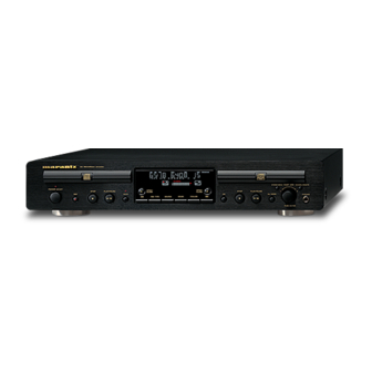
CD RECORDER DR6050
Recordable
ReWritable
STANDBY
POWER
ON/OFF
OPEN/
STOP
PLAY/PAUSE
CLOSE
REC
CDR
REC TYPE
TABLE OF CONTENTS
DR6050
DR6050 /
Compact Disc Recorder
STORE/MENU
OPEN/
STOP
PLAY/PAUSE
CLOSE
CD
DJ MODE
SOURCE
ERASE
FINALIZE
F1N, /K1G, /N1G
/F1B, /K1B, /N1B, /U1B
EASY JOG
CANCEL/DELETE
PHONES
PUSH ENTER
PAGE
R
386K855010 MIT
3120 785 22370
First Issue 2000.12
Advertisement
Table of Contents

Related Manuals for Marantz DR6050 series


Summary of Contents for Marantz DR6050 series
-
Page 1: Table Of Contents
Service DR6050 / F1N, /K1G, /N1G /F1B, /K1B, /N1B, /U1B Manual Compact Disc Recorder www.electronicsrepair.net CD RECORDER DR6050 Recordable ReWritable STANDBY STORE/MENU EASY JOG CANCEL/DELETE POWER ON/OFF OPEN/ OPEN/ STOP PLAY/PAUSE STOP PLAY/PAUSE CLOSE CLOSE DJ MODE PHONES REC TYPE SOURCE ERASE FINALIZE... - Page 2 MARANTZ Parts for your equipment are generally available to our National Marantz Subsidiary or Agent. ORDERING PARTS : Parts can be ordered either by mail or by Fax.. In both cases, the correct part number has to be specified.
-
Page 3: Servicing The Dr6000
1. Servicing the DR6050 1.1 INTRODUCTION: The DR6050 is the consumer version of a CD recorder, this means that the SCMS (Serial Copy Management System) is included. The DR6050 can only record on the Audio CDRs (Consumer Use). The DR6050 is suitable for recording and playback of CD-R W discs (CD-Re Writable disc). Playback &... - Page 4 1.2.1 CDR loader (CDR main module CDL4009 or MAR770): This complete CDR loader is considered as not repairable in the field. therefore this module will be repaired centrally. A module exchange procedure will be set up for this purpose. The module can be removed from the product by removing 4 screws and the transformer (see demounting the CDR module on page 1-7), and loosing the connectors.
-
Page 5: Technical Specifications
2 TECHNICAL SPECIFICATIONS GENERAL System ....................Compact disc digital audio Number of channels ................2 (stereo) Applicable discs ..................CD, CD-R (digital audio), CD-RW (digital audio) Power Requirement F version ................... AC 100 V 50 / 60 Hz K version ................... AC 110 V / 220 V 50 /60 Hz N version ................... -
Page 6: Warnings
3. WARNINGS WARNING WAARSCHUWING All ICs and many other semiconductors are susceptible to Alle IC´s en vele andere halfgeleiders zijn gevoelig voor electrostatic discharges (ESD). Careless handling during electrostatische ontladingen (ESD). repair can reduce life drastically. Onzorgvuldig behandelen tijdens reparatie kan de levensduur When repairing, make sure that you are connected with the drastisch doen vermindern. -
Page 7: Service Hints
4. SERVICE HINTS 5. SERVICE TOOLS Audio signals disc 4822 397 30184 Disc without errors (SBC444)+ Disc with DO errors, black spots and fingerprints (SBC444A) 4822 397 30245 Disc (65 min 1kHz) without no pause 4822 397 30155 Max. diameter disc (58.0 mm) 4822 397 60141 Torx screwdrivers Set (straight) - Page 8 Diangostic Software Dealer mode 6.2.2 Requirements to perform the test • Working keyboard to start up the test. The purpose of the dealer mode is to prevent people taking out • Working local display to check the output messages. the CD inside the player at exhibitions, showrooms etc.. This mode disables the open/close function of the player.
- Page 9 Electrical service diagnostics ELECTRICAL SERVICE DIAGNOSTICS (software versions, test for defective components) If power ON, switch power OFF Load CD-DA disc (SBC444A) Press <PLAY> + <F FWD> simultaneously and switch ON unit PLAYER LOADER TESTS INFORMATION CDR LOADER TEST Display : ABORT TEST CD-DA disc must be loaded "PLAYER ID"...
- Page 10 6.3.1 Description disc test is executed to check focus control, disc motor control, radial control and jump grooves control. The disc test is performed by audio play-back of 5 seconds at the beginning, The intention of the electrical service diagnostics is to show the middle and end of the disc.
- Page 11 6.4.2 Requirements to perform the test 6.5.1 Description Working keyboard to cycle through the tests and to start up This test is initiated by pressing [ERASE] and [RECORD] the test. simultaneously while switching on the unit. The player will Working local display to check the output messages. erase a complete CD-RW disc (including PMA and ATIP lead out area) at speed N=2.
-
Page 12: Faultfinding Trees
Faultfinding trees CDR-Module NO DISC LOADED SWITCH ON POWER CHECK: MAINS, MAINS CABLE POWER SUPPLY (SEE FAULT FINDING GUIDE PSU) WIRING ON/OFF SWITCH FUSES VOLTAGES DISPLAY (SEE FAULT FINDING GUIDE DISPLAY BOARD) DISPLAY? WIRING SUPPLY VOLTAGES CLOCK SIGNAL 8MHz CONTROL SIGNALS KEYBOARD STANDBY LED ELECTRICAL SERVICE DIAGNOSTICS:... - Page 13 CD-DA DISC LOADED CHECK: WIRING POWER SUPPLY VOLTAGES DISC ELECTRICAL SERVICE DIAGNOSTICS: DETECTION & READING? REPLACE CDR MODULE IF "DERRn" OR "BERRn" ERROR OCCURS CHECK: DISC: DIRT, SCRATCHES, DAMAGED... DISPLAY: ELECTRICAL SERVICE DIAGNOSTICS: “CD” & REPLACE CDR MODULE IF "DERRn" T.O.C.
- Page 14 CD-R DISC LOADED CHECK: DISC WIRING DETECTION & POWER SUPPLY VOLTAGES READING? ELECTRICAL SERVICE DIAGNOSTICS: REPLACE CDR MODULE IF "DERRn" OR "BERRn" ERROR OCCURS CHECK: DISPLAY: DISPLAY: DISC: DIRT, SCRATCHES, DAMAGED... “CD R” & “CD” & ELECTRICAL SERVICE DIAGNOSTICS: OPC INFO? T.O.C.
- Page 15 CD-RW DISC LOADED CHECK: DISC WIRING DETECTION & POWER SUPPLY VOLTAGES READING? ELECTRICAL SERVICE DIAGNOSTICS: REPLACE CDR MODULE IF "DERRn" OR "BERRn" ERROR OCCURS CHECK: DISPLAY: DISPLAY: DISC: DIRT, SCRATCHES, DAMAGED... “CD RW” & “CD” & ELECTRICAL SERVICE DIAGNOSTICS: OPC INFO? T.O.C.
- Page 16 CD Module CD MODULE NO DISC POWER ON CHECK FLEX CONNECTION FROM CDR MAIN BOARD POWER SUPPLY +5V, +12V AT TESTPOINTS 28 AND 27 +5V AT CONN. 1000 PINS 1 AND 3 +5V AT IC7005 PIN 14 +3V3 AT IC7000 PINS 5,17,21,57, CHECK SAFETY RESISTORS DISC +5V AT IC7020 PIN 25 DETECTION...
- Page 17 CD MODULE PLAYBACK PRESS <PLAY> DAC 7309 TESTPOINTS 20, 21, 22 : I 2 S AT INPUT OF DAC 7309 CHECK POWER SUPPLY PINS 4, 13 CHECK CLK11 AT PIN 6 : 11.2896MHz AUDIO? PIN 11 : MUTE HIGH? TESTPOINTS 23, 24 : ANALOG OUTPUT? REPLACE DAC 7309 OPAMP 7120 TESTPOINTS 23, 24 : ANALOG OUTPUT?
-
Page 18: Faultfinding Guide
Faultfinding Guide Display controller TMP87C874F Display Board TMP87CH74F ( QY01) is a high speed and high performance 8-bit single chip microprocessor, containing 8-bit A/D 8.1.1 Description of display board conversion inputs and a VFT (Vacuum Fluorescent Tube) driver. In this application, its functions are : General description slave microprocessor. - Page 19 8.1.2 Test instructions Grid lines Level and timing of all grid lines, G1-->G15, can be checked either at the FTD itself or at the display controller. Grid lines Supply voltages G13, G14 and G15 each have an extra current amplifier in line The display board receives several voltages via connector : QY02 for G13, QY03 for G14 and QY04 for G15.
- Page 20 The pulses created this way arrive at pin 16 and 17 of the display controller. The first pulse to arrive tells the controller the PM3392A direction of the rotation. Counting the pulses reveals the amount of rotation. Combining and decoding this information, the display controller will execute the appropriate task.
- Page 21 8.1.3 Display board troubleshooting guide SWITCH POWER ON, EXIT STAND BY MODE CHECK : SUPPLY VOLTAGES -35V ± 5 % at conn. JY01-2 ± 10% bet ween conn. JY01-1 and JY01-3 DISPLAY? ± 5 % at conn. JY01-10 CLOCK SIGNAL 8Mhz at pins 8, 9 of QY01 CONTROL SIGNALS RESETN 3V3 (high) at conn.
- Page 22 Power Supply Unit P816 cycle is regulated so that the output voltages are independent of load or input voltage variations. The controlling device MC44603 is an integrated pulse width modulator. A clock 8.2.1 Description of P816 signal initiates power pulses at a fixed frequency. The termination of each output pulse occurs when a feedback MOSFET Q825 is used as a power switch controlled by the signal of the inductor current reaches a threshold set by the...
- Page 23 Pin function description Description Name This pin is the positive supply of the IC. The operating voltage range after start-up is 9.0 to 14.5 V. The output high state (VOH) is set by the voltage applied to this pin. Peak currents up to 750 mA can be sourced or sunk, suitable for driving either MOSFET or bipolar transistors. Output The groundpin is a single return, typically connected back to the power source.
- Page 24 Block diagram of MC44603 Vref Iref Vref DEMAGNETISATION enable DETECT DEMAGNETISATION REFERENCE SUPPLY UVL01 MANAGEMENT BLOCK INITIALISATION BLOCK Iref VOSC PROT VOSC SYNC INPUT OSCILLATOR 1Set BUFFER LATCH RF STANDBY Vstby 1Reset STANDBY RP STANDBY (REDUCED FREQUENCY) 2.5V THERMAL SHUTDOWN Vref Iref VS8 OUT...
- Page 25 is switched off when the current sense level exceeds the level at the output of the error amplifier. TimeON phase : A drain current will flow from the positive CH1 2 supply at pin 2 of the transformer through the transformer's PM3394B CH3 2 V~ ALT MTB5.00us- 0.90dv ch1- primary winding, the MOSFET and Rsense to ground.
- Page 26 Circuit description of P816 Demagnetisation The auxiliary winding (7-9) voltage is used to detect magnetic saturation of the transformer core and connected via R801 to Input circuit pin 8 of Q810. During the demagnetisation phase, the output The input circuit consists of a lightning protection circuit and an will be disabled.
- Page 27 8.2.2 Troubleshooting P816 Check fuse F820 and replace if necessary Check DC voltages Power supply unit OK +5V, +12V, -8V, VFTD (-35V),VDC1-VDC2 (3V8) Disconnect power supply unit from CDR main board Connect dummy load resistors 10W, 15 ohm at +5V, +12V and ground Check DC voltages Power supply is OK +5V, +12V, -8V, VFTD, VDC1-VDC2...
- Page 28 Connect on pin 2 of position 1208 a clock signal of 8.4672 MHz ( 100ppm minimum rise time of 50ns and at TTL level CDM V AM1250 Loader assy (0V and +5V). HF amp. Keep microprocessor 7202 in reset by forcing pin 7 at Trig enta Diode signals position 1208 to +5V.
- Page 29 Pin Configuration Location Value DC 7022 5.8V ± 10% 7022 5.8V SBSY 7022 5.8V HFREF SFSY 7022 5.8V HFIN 7021 5.8V ISLICE 7021 5.8V SSA1 7021 TRAY- 5.8V TEST3 DDA1 7021 TRAY+ 5.8V STATUS CL96532086_054.eps SILD 080999 SAA7324 Figure 8-25 RESET 8.3.5 BA6856FP Turn Table Motor Driver (7020)
- Page 30 Motor controller truth table Input conditions conn 1006 pin Outputs conn 1006 Test points on driver UCOIL VCOIL WCOIL HALL_U HALL_V HALL_W CL96532086_055.eps 080999 Figure 8-26 Hall-elements input signal voltage levels Input voltage Level Tolerance Unit CL96532086_056.eps 080999 Figure 8-27 8.3.6 Tray Control Description...
- Page 31 8.3.7 HF Path another amplification and filtering circuit. The filtering again is controlled by the S1 and S2 lines, dependant on whether the disc starts up (speed n=1, S1 and S2 Low), disc plays at speed Description n=1 (S1 Low, S2 High) or disc plays at speed n=2 (S1 and S2 The pre-amplified HF-signal is presented to both n=1 and n=2 High).
- Page 32 Transfer Characteristics function generator as a sine wave generator with output level Set the power and reset connections as described above in of 1Vtt. Check this AC value with an AC mV-meter connected "1.1.1. Supply Voltages". Connect a function generator via a to the input (pin 2) of the CD10 (7000) : serial resistor of 1k5 to pin 4 of connector 1000.
- Page 33 Measurements 1200 - 17 AMPLIFIER CLK11 1200 - 19 NMUTE CL96532086_062.eps 080999 Figure 8-33 Keep processor 7202 in reset by forcing pin 7 of connector 1208 to +5V. This puts the processor outputs in tristate. Check the reset at pin 4 of processor 7202 to make sure that the processor is in reset.
-
Page 34: Wiring Diagram
9. WIRING DIAGRAM DISMOUNTING ADDITIONAL CABLES De-soldering and remove cables W651 from the loader PCB. W651 REMARK When replace the CDR module MAR775 to + side 2430 the new one. It is necessary to add removed cables at same positions as follows; + side 2424 .. - Page 35 W801 WY01(at conn.F934of WY02 WY03 WY04 POWER SUPPLY PCB TERMINAL PCB CDR main board) P816 PP16 J801 VDC2 STAND BY J851 JJ01 VFTD JF52 J682 VDC1 PULS J652 SYS RESET PULS IIC DATA WC02 IIC CLOCK DISPL INT WC03 1410 1500 1708 F934...
-
Page 36: Block Diagram
10. BLOCK DIAGRAM CDR MAIN BOARD CDL 4009 LOADER ASSY 7703 7330 1500 CDM3800 0205 1330 FLASH HALL +12V 11 WIRES POWER SUPPLY DRIVE, HALL FEEDBACK MOTOR FLEX 11P DRIVER VDC1, VDC2, VFTD UNIT BA6856FP TURN ADDRESS DATA TABLE 7702 DISPLAY ASSY 7008 7300... -
Page 37: Schematic Diagram And Parts Location
11. SCHEMATIC DIAGRAM AND PARTS LOCATION C701 PY16 J701 PP16 DISPLAY 100p L701 L702 ANALOG JJ01 INPUT C702 R655 R651 R653 LT03 100p 100k L651 DOBM QN51 C651 2SC2878A RN53 100p COAX 2.2K QN53 RN51 J651 2SC2878A 2.2K C653 220/16V RN54 2.2K MUTE... - Page 38 SWITCHING POWER SUPPLY PCB. (P816) Q851 L831 LM317 L854 µH L831 L853 D851 µH D802 Q892 AG01 C892 S1WB R853 PC123F 100/25 L825 D806 C819 C825 470pF R819 G815 C820 250V R852 C855 /400V 330k C827 C854 0.01 0.22 Q825 J801 470pF C851...
- Page 39 PP16 P916 QN54 QN53 QN58 QN57 QF52 QF51 Q311 Q681 QN52 QN51 QG56 QN55 DIGITAL ANALOG REC-IN CD/CDR COAX CDR/CD ANALOG DIGITAL L902 J901 SF51 JT02 JT52 J681 L681 J311 JT01 LT01 J301 J701 J651 JT51 JF51 RC-5 LT51 U071 L901 C301 CT03...
-
Page 40: Exploded View And Parts List
12. EXPLODED VIEW AND PARTS LIST W8 0 1 5 1 2 6 3 X8 ( M) MARK MAT ERIAL / F INISH SYMBO L ST YL E PART S NAME 5 1 2 8 5 1 1 0 + B. H. M. SCREW ( M ) ST EEL / COPPER 3 X8 ( M) - Page 41 PACKING 001B GOLD 9964 000 06396 FRONT PANEL AL GLD 386K248110 001T /F USER MANUAL F 386K851110 002B 4822 454 11825 BADGE MARANTZ BL PAINT 185J251010 001T /K USER MANUAL ENG/CHI 386K851350 003B 9965 000 01393 LENS STANDBY LED 312J355010 001T /N 9965 000 06373 USER MANUAL 9 LANG.
-
Page 42: Electrical Parts List
13. ELECTRICAL PARTS LIST NOTE ON SAFETY FOR FUSIBLE RESISTOR : ASSIGNMENT OF COMMON PARTS CODES. RESISTORS The suppliers and their type numbers of fusible resistors : 1) GD05 × × × 140, Carbon film fixed resistor, ±5% 1/4W are as follows; : 2) GD05 ×... - Page 43 VERS. PART NO. VERS. POS. POS. PART NO. PART NO. PART NO. DESCRIPTION DESCRIPTION COLOR COLOR (FOR PCS) (FOR PCS) (MJI) (MJI) P816-POWER P816-RESISTORS (COMMON) CIRCUIT BOARD CARBON FILM FIXED RES. P816-CAPACITORS ±5% 1/6W : R801-R808 R810 C801 9965 000 06375 CER. 82 pF J 500V CH DD15820550 R814 R815 R829 R851-R853 C810...
- Page 44 VERS. PART NO. VERS. POS. POS. PART NO. PART NO. PART NO. DESCRIPTION DESCRIPTION COLOR COLOR (FOR PCS) (FOR PCS) (MJI) (MJI) PP16-REAR PANEL JT02 4822 267 31369 OPT. CONNECTOR YJ15000090 CIRCUIT BOARD GP1F32T OPTICAL OUTPUT PP16-CAPACITORS JT51 4822 290 81638 TERMINAL 14X14 RA 1L1P BLK YT02010790 C301 4822 124 41539 ELECT.
- Page 45 VERS. POS. PART NO. PART NO. DESCRIPTION COLOR (FOR PCS) (MJI) SY15 4822 276 13732 PUSH SWITCH SKQNAE SP01013310 SY21 H/5MM 160GF VX01 9965 000 05916 DISPLAY UNIT FTD BJ727GNK HQ31208410 15GRID X 22ANODE XY01 4822 242 72066 SERAMIC VIB. CST8.0MHZ MT FQ08004010 ZY01 4822 130 11494 IR SENSOR RPM6936-V4 HW10004210...
Need help?
Do you have a question about the DR6050 series and is the answer not in the manual?
Questions and answers