Table of Contents
Advertisement
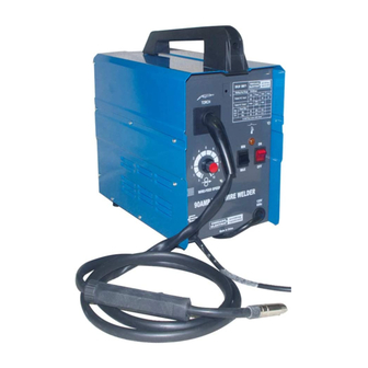
90 Amp flux wire
welDer
44567
ASSEMBLY AND OPERATING INSTRUCTIONS
®
3491 Mission Oaks Blvd., Camarillo, CA 93011
Visit our Web site at http://www.harborfreight.com
TO PREVENT SERIOUS INjURY,
READ AND UNDERSTAND ALL WARNINGS
AND INSTRUCTIONS BEFORE USE.
Copyright
2000 by Harbor Freight Tools
. All rights reserved. No portion of this manual or any
©
®
artwork contained herein may be reproduced in any shape or form without the express written
consent of Harbor Freight Tools.
For technical questions and replacement parts, please call 1-800-444-3353.
Revised Cover Page 02/03; Manual revised 09/05
Advertisement
Table of Contents

Related Manuals for Chicago Electric 44567


Summary of Contents for Chicago Electric 44567
- Page 1 90 Amp flux wire welDer 44567 ASSEMBLY AND OPERATING INSTRUCTIONS ® 3491 Mission Oaks Blvd., Camarillo, CA 93011 Visit our Web site at http://www.harborfreight.com TO PREVENT SERIOUS INjURY, READ AND UNDERSTAND ALL WARNINGS AND INSTRUCTIONS BEFORE USE. Copyright 2000 by Harbor Freight Tools .
-
Page 2: Table Of Contents
Contents Specifications ................3 General Safety Rules ..............3 Specific Safety Rules ................5 Grounding....................8 Symbology ................... 10 Unpacking ..................11 Assembly ..................11 Installing the Wire Reel ................ 12 Changing Wire feed roller ..............13 Trigger Switch Replacement ............... 14 Operation ..................15 Before You Start Welding .............. -
Page 3: Specifications
SPECIFICATIONS Welding Current 63 ~ 68 amps; High setting: 79 ~ 90 amps 10% at 80 amps; 18% at 60 amps Duty Cycle (See explanation of Duty Cycle on page 15.) 120 VAC, 24 amps peak, single phase Power Consumption Should be connected to a 20 amp minimum dedicated circuit Heat Control 2 settings... -
Page 4: Electrical Safety
Distractions can cause you to lose control. Protect others in the work area from debris such as chips and sparks. Provide barriers or shields as needed. Electrical Safety Avoid body contact with grounded surfaces such as pipes, radiators, ranges, and refrigerators. -
Page 5: Specific Safety Rules
Use clamps (not included) or other practical ways to secure and support the workpiece to a stable platform. Holding the work by hand or against your body is unstable and may lead to loss of control. Do not force the tool. Use the correct tool for your application. The correct tool will do the job better and safer at the rate for which it is designed. - Page 6 Unplug before performing maintenance. Always unplug the Welder from its electrical outlet before performing any inspection, maintenance, or cleaning procedures. Never leave the Welder unattended while energized. Turn power off if you have to leave the Welder. Maintain a safe working environment. Keep the work area well lit. Make sure there is adequate surrounding workspace.
- Page 7 easily visible smoke or flame may not be present for some time after the fire has started. Do not weld or cut in atmospheres containing dangerously reactive or flam- mable gases, vapors, liquids, and dust. Provide adequate ventilation in work areas to prevent accumulation of flammable gases, vapors, and dust.
-
Page 8: Grounding
Protect yourself from electric shock. Do not use outdoors. Insulate yourself from the workpiece and ground. Use nonflammable, dry insulating material if possible, or use dry rubber mats, dry wood or plywood, or other dry insulating material big enough to cover your full area of contact with the work or ground. WARNING! People with pacemakers should consult their physician(s) before using this product. -
Page 9: Extension Cords
Your tool must be plugged into an appropriate outlet, properly installed and grounded in accordance with all codes and ordinances. The plug and outlet should look like those in the following illustration. (See Figure A.) FIGURE A DOUBLE INSULATED TOOLS: TOOLS WITH TWO PRONG PLUGS Tools marked “Double Insulated”... -
Page 10: Symbology
cord contains at least the minimum wire size required. (See Figure C.) If you are using one extension cord for more than one tool, add the nameplate amperes and use the sum to determine the required minimum cord size. (See Figure C.) If you are using an extension cord outdoors, make sure it is marked with the suffix “W- A”... -
Page 11: Unpacking
UNPACKING When unpacking, check to make sure the following parts are included: Flux Wire Welder, Shade #10 Face Shield (38), Torch (1), Ground Cable (33), Wire Brush / Hammer (39), Power Cord (32), Wire Spool, Spare Welding Tip, and Contact Tip Wrench (43). This unit is packed with a protective light film of oil, wipe the unit of with a clean rag prior to assembly. -
Page 12: Installing The Wire Reel
Wire Feed Tension Adjusting Adjusting Wire Sheath Screw (37) Spring (36) Cover (31) Handle (30) Cover Locking Spring (8) Wire Reel (27) INSTALLING THE WIRE REEL WARNING! Turn the welder OFF and unplug it before proceeding. Press on the Cover Locking Spring (8), then lift the Cover (31) using Handle (30), to expose the Wire Feed Unit (23). -
Page 13: Changing Wire Feed Roller
Turn the Nozzle (3) counterclockwise while pulling to remove. Using the third oval hole on the provided Wrench (43), turn the Contact Tip (2b) counterclockwise and remove. Lay the Torch Cable out in a straight line so that the wire moves through it easily. -
Page 14: Trigger Switch Replacement
Remove the Wire Feed Roller (34) and install one with the proper size (.030”) facing Reassemble the Roller Bracket (44), Screws (45), and Washers (46). Put the welding wire into the top groove on the Roller, if it is not already in place. Swing the Wire Feed Adjusting Spring (36) down while pressing it forward to latch it over the Tension Adjusting Screw (37). -
Page 15: Operation
Connect the new Switch (1c); polarity does not matter. When reinstalling, make sure that the new Switch fits securely in place. Reassemble, reversing the steps on the previous page. Put on appropriate safety equipment, as explained in the safety section of this manual. After the unit is fully assembled, plug the Welder back in and turn it back ON. -
Page 16: Setting Up The Weld
SETTING UP THE WELD WARNING! Use care not to touch the welding tip to grounded material whenever the unit is plugged in. This unit is what is referred to as a “hot tip” welder, meaning that current is available to the wire at all times that the power Switch (7a) is in the ON position. -
Page 17: Holding The Torch
objects, turn the Power Switch to the ON position. Orient yourself on the area to be welded, then place the Face Shield over your eyes. Warning: Never look at the ignited arc without ANSI approved, arc shaded, eye protec- tion in a full face shield. Permanent eye damage or blindness can occur. Skin burns can occur. -
Page 18: Weld Settings Chart
For technical questions, please call 1-800-444-3353; SKU 44567 Page 18 Troubleshooting section at end of manual. -
Page 19: Weld Diagnosis
WELD DIAGNOSIS WELD PENETRATION ExCESS OR BURN-THROUGH PROPER INADEqUATE Weld droops on top and Weld is visible underneath and Weld does not contact the joint underneath, or falls through bulges slightly on top. fully, just on the surface. entirely, making a hole. Cross seCtIons POSSIBLE CAUSES AND SOLUTIONS POSSIBLE CAUSES AND SOLUTIONS... - Page 20 POROSITY CROOKED/WAVY BEAD Small cavities or holes in the bead. VIew VIew POSSIBLE CAUSES AND SOLUTIONS POSSIBLE CAUSES AND SOLUTIONS 1. Stickout too long: 1. Stickout too long: Reduce stickout. Reduce stickout. 2. Inaccurate welding: 2. Dirty workpiece or welding wire: Use two hands or rest hand on steady Make certain that workpiece and wire are surface.
-
Page 21: Maintenance
MAINTENANCE Warning: Before performing any maintenance on the Welder, unplug the Power Cord from the electrical outlet and allow all parts of the welder to cool thoroughly. Periodically remove the Right and Left side panels (12 and 13), and using compressed air, blow out all dust from the interior. -
Page 22: Parts Lists And Diagrams
PARTS LISTS AND DIAGRAMS WIRING SCHEMATIC For technical questions, please call 1-800-444-3353; SKU 44567 Page 22 Troubleshooting section at end of manual. -
Page 23: Parts List
PARTS LIST Part Description q’ty Part Description q’ty Back Handle Wire Feed Unit Front Handle Reel Spring Trigger Switch Wing Nut, M6 Handle Lock Ring Reel Locking Knob Torch Tube Wire Reel .9 mm Contact Tip Reel Holder Nozzle Self-tapping Screw, ST4.2*25 Liner Handle Fixing Pole (A) for Gun Body... -
Page 24: Assembly Diagram
ASSEMBLY DIAGRAM NOTE: Some parts are listed and shown for illustration purposes only and are not avail- able individually as replacement parts. For technical questions, please call 1-800-444-3353; SKU 44567 Page 24 Troubleshooting section at end of manual. - Page 25 REV 10/06 For technical questions, please call 1-800-444-3353; SKU 44567 Page 25 Troubleshooting section at end of manual.
-
Page 26: Troubleshooting
TROUBLESHOOTING IMPORTANT! Be CERTAIN to shut off the Welder, disconnect it from power, and discharge the torch to ground before adjusting, cleaning, or repairing the unit. WIRE FEED MOTOR RUNS BUT WIRE DOES NOT FEED PROPERLY POSSIBLE CAUSES AND SOLUTIONS 1. - Page 27 TROUBLESHOOTING (continued) IMPORTANT! Be CERTAIN to shut off the Welder, disconnect it from power, and discharge the torch to ground before adjusting, cleaning, or repairing the unit. POWER SWITCH (7A) DOES NOT LIGHT WHEN SWITCHED ON POSSIBLE CAUSES AND SOLUTIONS 1.
-
Page 28: Weak Arc Strength
TROUBLESHOOTING (continued) IMPORTANT! Be CERTAIN to shut off the Welder, disconnect it from power, and discharge the torch to ground before adjusting, cleaning, or repairing the unit. WIRE FEEDS, BUT ARC DOES NOT IGNITE POSSIBLE CAUSES AND SOLUTIONS 1. Improper ground connection: Make certain that the workpiece is contacted properly by the Ground Clamp and that the workpiece is properly cleaned near the ground clamp and the welding location.
Need help?
Do you have a question about the 44567 and is the answer not in the manual?
Questions and answers