Duerkopp Adler 609 Instruction Manual
Hide thumbs
Also See for 609:
- Service instructions manual (36 pages) ,
- Instruction manual (26 pages) ,
- Parts list (22 pages)
Table of Contents
Advertisement
Quick Links
Download this manual
See also:
Instruction Manual
Postfach 17 03 51, D-33703 Bielefeld • Potsdamer Straße 190, D-33719 Bielefeld
Telefon +49 (0) 521 / 9 25-00 • Telefax +49 (0) 521 / 9 25 24 35 • www.duerkopp-adler.com
Ausgabe / Edition:
Änderungsindex
10/2007
Rev. index: 01.0
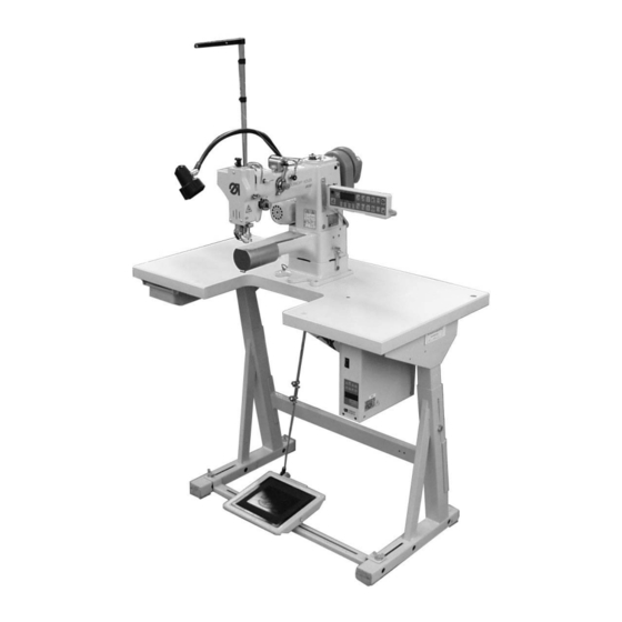
Spezialnähmaschine
Printed in Federal Republic of Germany
609
Betriebsanleitung
Instruction manual
Teile-Nr./Part.-No.:
0791 609741
D
GB
Advertisement
Table of Contents

Related Manuals for Duerkopp Adler 609


Summary of Contents for Duerkopp Adler 609
-
Page 1: Instruction Manual
Spezialnähmaschine Betriebsanleitung Instruction manual Postfach 17 03 51, D-33703 Bielefeld • Potsdamer Straße 190, D-33719 Bielefeld Telefon +49 (0) 521 / 9 25-00 • Telefax +49 (0) 521 / 9 25 24 35 • www.duerkopp-adler.com Ausgabe / Edition: Änderungsindex Teile-Nr./Part.-No.: 10/2007 Rev. - Page 2 Alle Rechte vorbehalten. Eigentum der Dürkopp Adler AG und urheberrechtlich geschützt. Jede, auch auszugsweise Wiederverwendung dieser Inhalte ist ohne vorheriges schriftliches Einverständnis der Dürkopp Adler AG verboten. All rights reserved. Property of Dürkopp Adler AG and copyrighted. Reproduction or publication of the content in any manner, even in extracts, without prior written permission of Dürkopp Adler AG, is prohibited.
- Page 3 Foreword This instruction manual is intended to help the user to become familiar with the machine and take advantage of its application possibilities in accordance with the recommendations. The instruction manual contains important information on how to operate the machine securely, properly and economically. Observation of the instructions eliminates danger, reduces costs for repair and down-times, and increases the reliability and life of the machine.
-
Page 4: General Safety Instructions
General safety instructions The non-observance of the following safety instructions can cause bodily injuries or damages to the machine. 1. The machine must only be commissioned in full knowledge of the instruction book and operated by persons with appropriate training. 2. -
Page 5: Table Of Contents
Content Page: Part 2: Installation Instructions Class 609 Scope of delivery ..........General and transport packing . -
Page 7: Scope Of Delivery
Scope of delivery What items are supplied depends on your order. Prior to assembling, please check that all the required parts are present. This instruction applies to a special sewing machine of which all individual components are delivered by the Dürkopp Adler AG. Basic equipment: –... -
Page 8: Assembling The Stand
Assembling the stand 3.1 Assembling the stand components (MG55-3 stand) – Assemble the components as shown in the illustration above. – Turn the set screw 2 to ensure the stand’s stability. Each of the stand’s four feet must touch the ground! –... -
Page 9: Assembling The Table Plate And Mounting The Control Unit
3.2 Assembling the table plate and mounting the control unit The positions of the components that are to mounted are indicated in the following sketch. Punch-mark for the stand Control Mains socket (optional add-on kit) Cable channel Punch-mark for set value initiator Drawer The measures in brackets are auxiliary sizes defined by the components. - Page 10 – Screw on the drawer 4 with the sockets underneath the left half of the table plate. – Fix the control unit 1 with three woodscrews (5x30) underneath the right half of the table plate . – Screw on the holder for the strain relief of the mains cable underneath the table plate.
-
Page 11: Setting The Working Height
3.3 Setting the working height – The working height can be adjusted between 740 and 900 mm (measure to the upper edge of the table plate). – Undo screws 1 on the stand braces. – Adjust the table plate horizontally to the desired working height. In order to prevent tilting, the table plate must be pulled out or pushed in regularly on both sides. -
Page 12: Mounting The Machine Head
Mounting the machine head 4.1 Fitting the machine head on the table plate Fixing the machine head on the table plate – Fix the socket 2 of the machine head with the four screws 3 (M6X60), washers and nuts onto the table plate. Tilting the machine head –... -
Page 13: Earthing
4.2 Earthing The earthing cable conducts static electricity charges of the machine head via the sewing drive to the ground. – Connect the earthing cable with push-on contact, flat plug, toothed washer onto the earthing connection 2 of the control. –... -
Page 14: Mounting The Table And Pedal Extension (Optional Equipment)
Mounting the table and pedal extension (optional equipment) 5.1 Mounting the table extension Mount the table extension according to the sketch below: Preassembling the bracket – Preassemble the bracket according to the sketch on left. Preassembling the table extension – Turn the table plate upside down and put the insert plate into the cutout provided for it. -
Page 15: Mounting The Pedal Extension
Fix the table extension on the table plate – Screw the clamp levers into the thread insert, in order to leave an interstice of > 4 mm. Shift the table extension without the insert plate but with the 4 in a –... -
Page 16: Sewing Drive
Sewing drive 6.1 Connecting the HoHsing HVP 70-4-ED-2-CE sewing drive ATTENTION! Only qualified electricians or other persons with an adequate training may work on the electrical equipment of this special sewing machine. The mains plug must be removed! The instruction manual of the drive’s manufacturer must imperatively be respected! 6.1.1 Connecting the control unit Connector sockets HoHsing HVP 70-4-ED-2-CE... -
Page 17: Mounting And Connecting The External Operating Panel C300
6.1.2 Mounting and connecting the external operating panel C300 – Screw the external operating panel 2 on the mounting bracket 1. – Screw the mounting bracket 1 laterally on the machine head. – Bring the connection cable downwards through the cutout in the table plate . -
Page 18: Connecting The Control Connection Of The Thread Trimmer And Thread Tension Release
6.1.4 Connecting the control connection of the thread trimmer and thread tension release – Bring the connection cable upwards through the hole of the table plate underneath the machine head base. – Connect the cables according to the attached 609 wiring diagram, part number 9890 609001 B and connect the cables to both plugs with two pins 1. -
Page 19: Checking The Mains Voltage And Connecting The Machine
Checking the mains voltage and connecting the machine ATTENTION! The rated voltage mentioned on the type plate and the actual mains voltage must be identical. – Fix an appropriate power plug on the cable end – Effectuate a power supply with 1x230V 50/60Hz Setting the sewing drive 8.1 Setting the HoHsing HVP 70-4-ED-2-CE sewing drive 8.1.1 Setting parameters of the control unit... - Page 20 Checking the positioning: – Turn on the main switch. – Briefly push the pedal forward. The sewing machine positions in thread lever upper dead center. – Push the pedal completely backwards and keep it pushed. The thread is trimmed. The sewing machine positions in thread lever upper dead center, if the needle return function is deactivated.
-
Page 21: Lubrication
Lubrication Caution: danger of injury ! Oil can cause skin eruptions. Avoid protracted contact with the skin. In the event of contact, thoroughly wash the affected area. CAUTION ! The handling and disposal of mineral oils is subject to legal regulation. Deliver used oil to an authorised collection point. -
Page 22: Sewing Test
10. Sewing test After completing the setting-up a sewing test must be carried out. – Insert the mains plug. Caution: danger of injury ! Turn off the main switch. The needle and hook thread may only be threaded in with the sewing machine switched off.
Need help?
Do you have a question about the 609 and is the answer not in the manual?
Questions and answers