Duerkopp Adler 669 Premium Operating Instruction
Hide thumbs
Also See for 669 Premium:
- Parts list (56 pages) ,
- Service instructions manual (52 pages) ,
- Instruction manual (46 pages)
Table of Contents
Advertisement
Quick Links
Download this manual
See also:
Instruction Manual
Advertisement
Table of Contents

Related Manuals for Duerkopp Adler 669 Premium


Summary of Contents for Duerkopp Adler 669 Premium
- Page 1 669 PREMIUM Operating Instructions...
- Page 2 IMPORTANT READ CAREFULLY BEFORE USE KEEP FOR FUTURE REFERENCE All rights reserved. Property of Dürkopp Adler AG and protected by copyright. Any reuse of these contents, including extracts, is prohibited without the prior written approval of Dürkopp Adler AG. Copyright © Dürkopp Adler AG 2016...
-
Page 3: Table Of Contents
Selecting the quick access function (softkey menu)......52 5.4.2 Setting the Speed parameter (Max. Speed) ........55 5.4.3 Setting the Thread cutter parameter (Thread Trim) ......56 5.4.4 Setting the Thread clamp parameter (Thread Clamp)...... 56 Operating Instructions 669 PREMIUM - 00.0 - 11/2016... - Page 4 Assembling the pedal and setpoint device ........107 Tabletop .................... 108 7.5.1 Completing the tabletop ..............108 7.5.2 Assembling the tabletop to the stand ..........109 Setting the working height ..............110 Assembling the control ..............111 Operating Instructions 669 PREMIUM - 00.0 - 11/2016...
- Page 5 Customer Service ................129 10.2 Messages of the software ..............130 10.2.1 Information messages ............... 130 10.2.2 Error messages ................. 134 10.3 Errors in sewing process ..............141 Technical data ................. 143 Appendix ..................147 Operating Instructions 669 PREMIUM - 00.0 - 11/2016...
- Page 6 Table of Contents Operating Instructions 669 PREMIUM - 00.0 - 11/2016...
-
Page 7: About These Instructions
Specifically, the chapter Setup p. 105 is important for specialists. Service Instructions are supplied separately. With regard to minimum qualification and other requirements to be met by personnel, please also follow the chapter Safety ( p. 9). Operating Instructions 669 PREMIUM - 00.0 - 11/2016... -
Page 8: Representation Conventions - Symbols And Characters
Lists are marked by bullet points. Result of performing an operation Change to the machine or on the display/control panel. Important Special attention must be paid to this point when performing a step. Operating Instructions 669 PREMIUM - 00.0 - 11/2016... -
Page 9: Other Documents
Each manufacturer has performed a hazard assessment for these purchased parts and confirmed their design compliance with applicable European and national regulations. The proper use of the built-in components is described in the corresponding manufacturer's instructions. Operating Instructions 669 PREMIUM - 00.0 - 11/2016... -
Page 10: Liability
This will ensure any claims against the transport company. Report all other complaints to Dürkopp Adler immediately after receiving the product. Operating Instructions 669 PREMIUM - 00.0 - 11/2016... -
Page 11: Safety
The power plug may only be assembled to the power cable by qualified specialists. Obligations Follow the country-specific safety and accident prevention regu- of the operator lations and the legal regulations concerning industrial safety and the protection of the environment. Operating Instructions 669 PREMIUM - 00.0 - 11/2016... -
Page 12: Signal Words And Symbols Used In Warnings
Signal words Signal words and the hazard they describe: Signal word Meaning DANGER (with hazard symbol) If ignored, fatal or serious injury will result WARNING (with hazard symbol) If ignored, fatal or serious injury can result Operating Instructions 669 PREMIUM - 00.0 - 11/2016... - Page 13 NOTICE (without hazard symbol) If ignored, property damage can result Symbols The following symbols indicate the type of danger to personnel: Symbol Type of danger General Electric shock Puncture Crushing Environmental damage Operating Instructions 669 PREMIUM - 00.0 - 11/2016...
- Page 14 Consequences of non-compliance. Measures for avoiding the danger. This is what a warning looks like for a hazard that could result in moderate or minor injury if the warning is ignored. Operating Instructions 669 PREMIUM - 00.0 - 11/2016...
- Page 15 Type and source of danger! Consequences of non-compliance. Measures for avoiding the danger. This is what a warning looks like for a hazard that could result in environmental damage if ignored. Operating Instructions 669 PREMIUM - 00.0 - 11/2016...
- Page 16 Safety Operating Instructions 669 PREMIUM - 00.0 - 11/2016...
-
Page 17: Machine Description
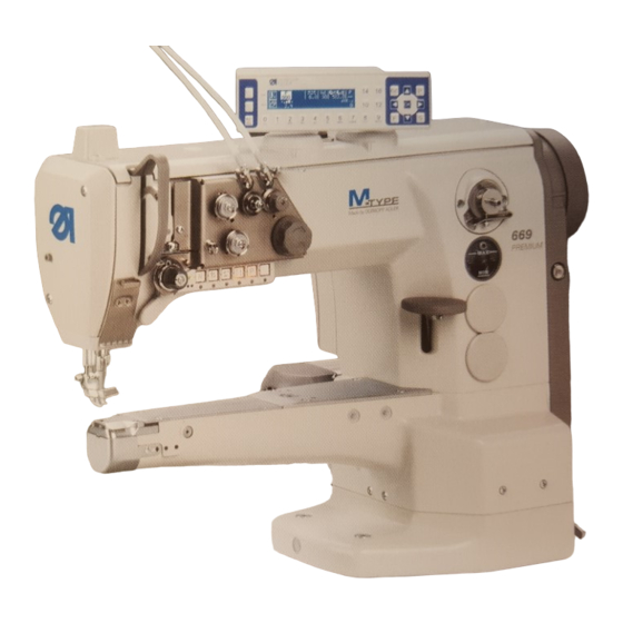
③ (1) - Programmable (4) - Oil level indicator thread tension (5) - Winder (2) - Push buttons (6) - Electronic handwheel (3) - Stitch adjustment lever (7) - Control panel OP3000 Operating Instructions 669 PREMIUM - 00.0 - 11/2016... -
Page 18: Proper Use
DIN EN 60204-31. Only authorized persons may work on the machine. Dürkopp Adler cannot be held liable for damages resulting from improper use. Operating Instructions 669 PREMIUM - 00.0 - 11/2016... -
Page 19: Declaration Of Conformity
Machine description Declaration of Conformity The machine complies with European regulations ensuring health, safety, and environmental protection as specified in the declara- tion of conformity or in the declaration of incorporation. Operating Instructions 669 PREMIUM - 00.0 - 11/2016... - Page 20 Machine description Operating Instructions 669 PREMIUM - 00.0 - 11/2016...
-
Page 21: Operation
Complete the following steps in preparation of sewing before starting to work: • Inserting/changing the needle • Threading the needle thread • Inserting and winding on the hook thread • Setting the thread tensions Operating Instructions 669 PREMIUM - 00.0 - 11/2016... -
Page 22: Switching On And Off The Machine
The indicator LED (1) and the POWER LED (3) illuminate. Switching off the machine To switch off the machine: Press the switch (2) to the O position. The indicator LED (1) and the POWER LED (3) go out. Operating Instructions 669 PREMIUM - 00.0 - 11/2016... -
Page 23: Switching On And Off The Sewing Lamp
Press button (2) if the sewing lamp is not yet illuminated. Switching off the dimmable sewing lamp To switch off the dimmable sewing lamp: Press switch (1) or (3) to the O position. The dimmable sewing lamp goes out. Operating Instructions 669 PREMIUM - 00.0 - 11/2016... -
Page 24: Inserting/Changing The Needle
Check the distance to the hook tip after inserting a needle with a different thickness. Fig. 4: Inserting/changing the needle ① ② ③ ④ (1) - Needle bar (3) - Groove (2) - Screw (4) - Hook Operating Instructions 669 PREMIUM - 00.0 - 11/2016... - Page 25 An incorrect hook distance can cause the following disturbances: • Changing to a thinner needle: • Missing stitches • Thread damage • Changing to a thicker needle: • Damage to the hook tip • Damage to the needle Operating Instructions 669 PREMIUM - 00.0 - 11/2016...
-
Page 26: Threading The Needle Thread
Turn off the machine before threading the thread. Fig. 5: Threading the needle thread (1) ① ② (1) - Hose guide (2) - Thread guide To thread the needle thread: Fit the thread reel on the reel stand. Operating Instructions 669 PREMIUM - 00.0 - 11/2016... - Page 27 Feed the thread clockwise around tensioner 2 (7). Feed the thread under the thread guide (6) to the thread tension spring (5). Lift the tightening lever (3) with the thread. Pull the thread under the spring tip (4). Operating Instructions 669 PREMIUM - 00.0 - 11/2016...
- Page 28 For machines with thread clamp (optional) 15. Insert the left thread through the left hole of the guide above the thread clamp. 16. Insert the thread through the left hole of the guide below the thread clamp. Operating Instructions 669 PREMIUM - 00.0 - 11/2016...
- Page 29 18. Feed the thread through the thread guide (14) on the needle bar. 19. Insert the thread through the needle eye in such a way that the loose thread end faces the hook. Operating Instructions 669 PREMIUM - 00.0 - 11/2016...
-
Page 30: Winding The Hook Thread
Turn off the machine before threading the thread. Fig. 9: Winding the hook thread (1) ① ② (1) - Thread guide (2) - Hose guide To wind the hook thread: Fit the thread reel on the reel stand. Operating Instructions 669 PREMIUM - 00.0 - 11/2016... - Page 31 Guide the thread to the bobbin (6). Fig. 11: Winding the hook thread (3) ⑨ ⑧ ⑦ (7) - Bobbin lever (9) - Cutter (8) - Bobbin shaft Operating Instructions 669 PREMIUM - 00.0 - 11/2016...
- Page 32 The cutter is automatically moved into its basic vertical position. 13. Pull off the full bobbin. 14. Tear off the thread behind the cutter (9). 15. Insert the full bobbin into the hook ( p. 31). Operating Instructions 669 PREMIUM - 00.0 - 11/2016...
-
Page 33: Changing The Bobbin
Move the needle to the top dead center. Pull off the hook cover (6) and fold it down. Remove the bobbin case upper section (2) with the empty bobbin. Remove the empty bobbin. Operating Instructions 669 PREMIUM - 00.0 - 11/2016... -
Page 34: Thread Tension
② ③ DA150018_V52_XX (1) - Identical needle thread and hook thread tension (2) - Hook thread tension higher than needle thread tension (3) - Needle thread tension higher than hook thread tension Operating Instructions 669 PREMIUM - 00.0 - 11/2016... -
Page 35: Setting The Needle Thread Tension
The hook thread tension must be set so that the resulting seam pattern is uniform. The basic setting for the tension spring is performed as follows: • When the bobbin case contains a full bobbin it must sink slowly under its own weight. Operating Instructions 669 PREMIUM - 00.0 - 11/2016... - Page 36 Set the tension spring (2) using the adjusting screw (3). • To increase the tension: Turn the adjusting screw (3) clockwise • To reduce the tension: Turn the adjusting screw (3) counterclockwise Operating Instructions 669 PREMIUM - 00.0 - 11/2016...
-
Page 37: Setting The Needle Thread Regulator
• To increase the tension: Slide the needle thread regulator (2) to the right • To reduce the tension: Slide the needle thread regulator (2) to the left Tighten the screw (1). Operating Instructions 669 PREMIUM - 00.0 - 11/2016... -
Page 38: Lifting The Sewing Feet
The thread cutter is activated, and the sewing feet are raised. 4.11 Sewing backwards with the stitch adjustment lever (optional) The electronic stitch adjustment lever on the machine arm reduces the stitch length down to sewing backwards in the lower end position. Operating Instructions 669 PREMIUM - 00.0 - 11/2016... - Page 39 To sew backwards with the stitch adjustment lever: Slowly push the stitch adjustment lever (1) down. The stitch length becomes smaller. In the lower end position, the machine sews backwards with the set stitch length. Operating Instructions 669 PREMIUM - 00.0 - 11/2016...
-
Page 40: Setting Quick Stroke Adjustment
The elevated sewing foot stroke is retained as long as the knee button is pushed to the right. • To switch off the elevated sewing foot stroke: Release the knee button (1). Operating Instructions 669 PREMIUM - 00.0 - 11/2016... -
Page 41: Quick Functions On The Push Buttons
Activating a function Press the desired button. The function is activated. The button lights up. Deactivating a function Press the desired button again. The function is deactivated. The button turns off. Operating Instructions 669 PREMIUM - 00.0 - 11/2016... - Page 42 Fully customizable The button is fully customizable. The machine comes configured so that the machine will switch to the next seam section when the button is pressed. Operating Instructions 669 PREMIUM - 00.0 - 11/2016...
-
Page 43: Assigning A Function To The Favorite Button
Turn all screws to their initial position (3) so that the slots of the screws are horizontal. Turn the screw (2) under the desired button 90° so that the slot is vertical (4). Operating Instructions 669 PREMIUM - 00.0 - 11/2016... -
Page 44: Sewing
• Press the pedal halfway back (position -1) The sewing feet are lifted. the sewing material • Position the sewing material. • Release the pedal. Sewing feet are lowered onto the sewing material. At seam beginning Operating Instructions 669 PREMIUM - 00.0 - 11/2016... - Page 45 • Press the pedal fully back (position -2) and keep it seam and there. End bartack is sewn, and thread is cut (if set). remove the Machine stops. sewing Needle is up. Sewing feet up. material • Remove the sewing material. Operating Instructions 669 PREMIUM - 00.0 - 11/2016...
- Page 46 Operation Operating Instructions 669 PREMIUM - 00.0 - 11/2016...
-
Page 47: Programming
Control panel OP3000 Fig. 23: Control panel ① ② (1) - Softkey button (2) - Softkey menu button All settings in the software for the 669 PREMIUM are performed using the OP3000 control panel. Button Function Numeric • Inputting the parameter value... - Page 48 Display on the control panel The display shows the menu items that can be selected. The activated menu point is shown inverted. Fig. 24: The active entry is shown inverted (example) 4 +000 +00 -013 Operating Instructions 669 PREMIUM - 00.0 - 11/2016...
-
Page 49: Switching On The Machine
Switching on the machine Fig. 25: Switching on the machine ① (1) - Main switch To switch on the machine: Switch on the main switch (1). The display briefly shows the software versions: Operating Instructions 669 PREMIUM - 00.0 - 11/2016... -
Page 50: Software Operating Modes
Fig. 28: Display in Manual mode 5 3.0 Software operating modes The software of the 669 PREMIUM has 3 available operating modes: • Manual mode (program 000) ( p. 50) Manual mode is the simplest operating mode. There are no programs/seam programs and no inputs for individual seam sections. - Page 51 Edit mode can be used to adjust, delete and copy seam programs. The individual modes and their uses are explained in detail later on. Operating Instructions 669 PREMIUM - 00.0 - 11/2016...
-
Page 52: Using Manual Mode
• Use ▲/▼ to change the stitch length Needle thread tension Value range: 01 - 99 • Use ◄/► to select the Needle thread tension parameter • Use ▲/▼ to change the needle thread tension Operating Instructions 669 PREMIUM - 00.0 - 11/2016... - Page 53 After the thread has been cut off, the display is retained. Measurement/counting restarts when sewing starts again. • Cancel the function • Exit the menu (changes remain saved) to return to the starting level • Confirm the settings • Activate the input Operating Instructions 669 PREMIUM - 00.0 - 11/2016...
-
Page 54: Selecting The Quick Access Function (Softkey Menu)
You can also assign a function to the softkey button. To select a quick access function: Press the softkey menu button. The following display appears: Fig. 30: Softkey menu To select a function: Press the numeric button under the desired function. Operating Instructions 669 PREMIUM - 00.0 - 11/2016... - Page 55 If sewing is stopped within the seam, the needle is posi- tioned up or down. Programming Activation of programming mode. BEFORE the seam Thread cutter Function active or inactive. IN the seam Operating Instructions 669 PREMIUM - 00.0 - 11/2016...
- Page 56 Possible button assignment for the softkey button (Automatic mode) Symbol Meaning Threading mode The needle bar moves to the defined position. The pedal is temporarily locked. Reset daily piece counter. Automatic stitch counting Function active or inactive. Operating Instructions 669 PREMIUM - 00.0 - 11/2016...
-
Page 57: Setting The Speed Parameter (Max. Speed)
It is possible to reduce the maximum speed at this point. The value of the maximum speed can be set in the software at technician level. Menu item Setting option (Max. Speed) 0050 – 3800 [rpm] Speed depending on subclass Operating Instructions 669 PREMIUM - 00.0 - 11/2016... -
Page 58: Setting The Thread Cutter Parameter (Thread Trim)
The value entered here corresponds to the degree number on the handwheel. Menu item Setting option (PointPos.°) 000 – 359 [°] Initial alignment stitch function Operating Instructions 669 PREMIUM - 00.0 - 11/2016... -
Page 59: Setting The Start Bartack Parameter (Start Tack)
Value range Speed Speed in bartack 0000 – 2000 ON/OFF Pedal Stop, Single stitches per pedal p. 59 ON/OFF Value range Thr.Tens.Def., Default needle thread tension 01 - 99 p. 59 Operating Instructions 669 PREMIUM - 00.0 - 11/2016... - Page 60 If this function is active, the same stitch length is used for the bartack as the one set in Manual mode. If this function is deacti- vated, a custom input can be entered. Operating Instructions 669 PREMIUM - 00.0 - 11/2016...
- Page 61 – even number of sections) or against the sewing direction (back- wards – odd number of sections), depending on the number of sections. Setting this parameter inverts the sewing direction of the bartack. Operating Instructions 669 PREMIUM - 00.0 - 11/2016...
-
Page 62: Set End Bartack Parameter (End Tack)
Value range Speed Speed in bartack 0000 – 2000 ON/OFF Pedal Stop, Single stitches per pedal p. 59 ON/OFF Value range Thr.Tens.Def., Default needle thread tension 01 - 99 p. 59 Operating Instructions 669 PREMIUM - 00.0 - 11/2016... - Page 63 This function is useful for the short stitch for the short thread cutter, for example. In this case, one less stitch is sewn in the last section. Operating Instructions 669 PREMIUM - 00.0 - 11/2016...
-
Page 64: Setting The Sewing Foot Lift Parameter (Foot)
Settings that are more complex and therefore require further explanation are described in more detail after the table. Menu items Setting option 1 Setting option 2 Value range 0000 – 5000 [ms] Monitor, t Clean p. 63 Operating Instructions 669 PREMIUM - 00.0 - 11/2016... - Page 65 If the parameter is not activated, only the LEDs on the machine arm give a warning if the bobbin is empty. Operating Instructions 669 PREMIUM - 00.0 - 11/2016...
- Page 66 LEDs on the machine arm give a warning if the bobbin is empty. It is only possible to resume sewing after ResetNeces ON/OFF changing the bobbin and confirming the message on the control panel. Operating Instructions 669 PREMIUM - 00.0 - 11/2016...
-
Page 67: Setting The Information Parameter (Info)
Menu item Meaning no display Pedal position Pedal (Value range 24 – -2) Material thickness detection Thick Handwheel position (Value range 000 – 359 [°]) Current speed Speed Bobbin stitch counter Bobbin Operating Instructions 669 PREMIUM - 00.0 - 11/2016... -
Page 68: Setting The Edge Stop Parameter (Edge Guide)
Menu items Setting option 1 Setting option 2 ON/OFF Stitchlen., Stitch length p. 69 linear Stitchlen. Min. speed Max. speed 2.OnOff Min. speed 2.On Min. speed Operating Instructions 669 PREMIUM - 00.0 - 11/2016... - Page 69 Thr.Tens., Needle thread tension p. 70 linear Thr.Tens. Min. speed Max. speed 2.OnOff Min. speed 2.On Min. speed FootPress., Sewing foot pressure p. 70 linear FootPress. Min. speed Max. speed Operating Instructions 669 PREMIUM - 00.0 - 11/2016...
- Page 70 DOES NOT switch to the base value for the parameter. Only after finishing the seam by cutting the thread is the base value for the parameter set again. Operating Instructions 669 PREMIUM - 00.0 - 11/2016...
- Page 71 Speed from which the 2 stitch Value range length should be used. 0000 – 4000 [rpm] 2.On Min. speed Speed from which the 2 stitch Value range length should be used. 0000 – 4000 [rpm] Operating Instructions 669 PREMIUM - 00.0 - 11/2016...
- Page 72 Min. speed Value range sewing foot pressure should start. 0000 – 4000 [rpm] Speed up to which the increase in Max. speed Value range sewing foot pressure should occur. 0000 – 4000 [rpm] Operating Instructions 669 PREMIUM - 00.0 - 11/2016...
-
Page 73: Setting The Material Thickness Detection Parameter (Fabric Thickness)
Stroke ThickMin ThickMax 2.OnOff ThickMin 2.On ThickMin Stitchlen., Stitch length p. 75 linear Stitchlen. ThickMin ThickMax 2.OnOff ThickMin 2.On ThickMin Thr.Tens., Needle thread tension p. 76 linear Thr.Tens. ThickMin ThickMax Operating Instructions 669 PREMIUM - 00.0 - 11/2016... - Page 74 Menu items Setting option 1 Setting option 2 2.OnOff ThickMin 2.On ThickMin FootPress., Sewing foot pressure p. 76 linear FootPress. ThickMin ThickMax Max.Speed, Speed p. 76 linear Max.Speed ThickMin ThickMax Operating Instructions 669 PREMIUM - 00.0 - 11/2016...
- Page 75 DOES NOT switch to the base value for the parameter. Only after finishing the seam by cutting the thread is the base value for the parameter set again. Operating Instructions 669 PREMIUM - 00.0 - 11/2016...
- Page 76 Value range 00.0 – 10.0 [mm] which the 2 sewing foot stroke height should be used. Material thickness from 2.On ThickMin Value range 00.0 – 10.0 [mm] which the 2 sewing foot stroke height should be used. Operating Instructions 669 PREMIUM - 00.0 - 11/2016...
- Page 77 Value range 00.0 – 10.0 [mm] which the 2 stitch length should be used. Material thickness from 2.On ThickMin Value range 00.0 – 10.0 [mm] which the 2 stitch length should be used. Operating Instructions 669 PREMIUM - 00.0 - 11/2016...
- Page 78 Value range 00.0 – 10.0 [mm] the increase in sewing foot pressure should start. Material thickness up to ThickMax Value range 00.0 – 10.0 [mm] which the increase in sewing foot pressure should occur. Operating Instructions 669 PREMIUM - 00.0 - 11/2016...
-
Page 79: Using Automatic Mode
0 – 9 and confirm with the OK button If you select program 000, the control selects Manual mode, p. 50. Seam sections Number of seam sections contained in the current program. Operating Instructions 669 PREMIUM - 00.0 - 11/2016... -
Page 80: Sewing In Automatic Mode
The number under the current seam section shows the number of stitches yet to be sewn / the outstanding length of the seam section. The program bar shows half the current seam section in bold. Operating Instructions 669 PREMIUM - 00.0 - 11/2016... - Page 81 Technician level. The s.p.m. option is set at the factory. Stop at the end of the seam section with thread cutting Switch between two seam sections without stopping Switch between two seam sections, with a stop, but without thread cutting Operating Instructions 669 PREMIUM - 00.0 - 11/2016...
- Page 82 Seam section forwards/backwards or go to start of seam section. Pedal halfway Lift sewing foot. back Pedal fully Cut off or cancel the program. back The program remains stopped at the cutoff point. Softkey menu, p. 52. Operating Instructions 669 PREMIUM - 00.0 - 11/2016...
-
Page 83: Canceling A Program In Automatic Mode
Press the OK button to load the program number. Choose a different program number using ▲/▼ or enter one with the numeric buttons 0 – 9 and then press the OK button Operating Instructions 669 PREMIUM - 00.0 - 11/2016... -
Page 84: Creating A Program Using Keyboard Input
The following display is shown, with preset values which can be specified at technician level. Fig. 38: Programming mode display 5 2.0 Operating Instructions 669 PREMIUM - 00.0 - 11/2016... - Page 85 Repeat steps 6 and 7 to define up to 30 seam sections if necessary. Press the ESC button. The program is saved. The machine switches to Automatic mode and the newly created program is selected. Operating Instructions 669 PREMIUM - 00.0 - 11/2016...
-
Page 86: Creating A Program Using Teach-In
• Use ◄/► to select the Stroke height parameter • Use ▲/▼ to change the stroke height Press the pedal and complete the seam section up to the desired position on the material. Operating Instructions 669 PREMIUM - 00.0 - 11/2016... -
Page 87: Adjusting Parameters For The Current Seam Section
OK button. Parameters for the current seam section: Symbol Description StitchCount Length of the seam section 0 = Manually step through > 1 = Number of stitches or length in mm Operating Instructions 669 PREMIUM - 00.0 - 11/2016... - Page 88 Lifting height of the sewing foot when sewing stops on the seam section. Backwards Backward stitches; when the parameter is activated, the section is sewn backwards. Center Guide Seam middle guide (only on 2-needle machines) Operating Instructions 669 PREMIUM - 00.0 - 11/2016...
-
Page 89: Adjusting Parameters For The Selected Program
Press the OK button to activate or deactivate the parameter ▲/▼ or use to edit the value and confirm the change by press- ing the OK button. Operating Instructions 669 PREMIUM - 00.0 - 11/2016... - Page 90 Daily piece counter, can be set to count either up or down. When the daily piece counter is activated, it must be reset once after entering a value using the function in the softkey menu to ensure it counts correctly. Operating Instructions 669 PREMIUM - 00.0 - 11/2016...
-
Page 91: Editing Programs
Press the P button. The control switches to Edit mode. The following information is shown, and the P in the program number field flashes: Fig. 40: Display in editing mode 5 2.0 Operating Instructions 669 PREMIUM - 00.0 - 11/2016... -
Page 92: Copying The Program
The P above the program number will flash. Press the softkey menu button. The softkey menu appears. Fig. 41: Softkey menu Press the numeric button under The following display appears: Operating Instructions 669 PREMIUM - 00.0 - 11/2016... - Page 93 5 2.0 If necessary, make changes to the newly copied program. Press the ESC button. The program is saved. The machine switches to Automatic mode and the newly created program is selected. Operating Instructions 669 PREMIUM - 00.0 - 11/2016...
-
Page 94: Deleting The Program
▲/▼ To delete further programs, select the program using repeat from step 3. Press the ESC button to go to Automatic mode. The machine switches to Automatic mode. Operating Instructions 669 PREMIUM - 00.0 - 11/2016... -
Page 95: Maintenance
Advanced maintenance work may only be carried out by qualified specialists ( Service Instructions). Maintenance interval Work to be carried out Operating hours Cleaning Removing lint and thread remnants Lubricating Lubricating the machine head Lubricating the hook Operating Instructions 669 PREMIUM - 00.0 - 11/2016... -
Page 96: Cleaning
Make sure no particles fly into the oil pan. NOTICE Property damage from soiling! Lint and thread remnants can impair the operation of the machine. Clean the machine as described. Operating Instructions 669 PREMIUM - 00.0 - 11/2016... - Page 97 • Hook (2) • Area around the needle (1) Cleaning steps: Switch off the machine at the main switch. Remove any lint and thread remnants using a compressed air gun or a brush. Operating Instructions 669 PREMIUM - 00.0 - 11/2016...
-
Page 98: Lubricating
For topping off the oil reservoir, use only lubricating oil DA 10 or oil of equivalent quality with the following specifications: • Viscosity at 40 °C:10 mm • Flash point: 150 °C Operating Instructions 669 PREMIUM - 00.0 - 11/2016... -
Page 99: Lubricating The Machine Head
If the inspection glass lights up red, the machine is not suffi- ciently supplied with oil. If the oil level is below the minimum level marking (3): Pour oil through the refill opening (1) but no higher than the maximum level marking (2). Operating Instructions 669 PREMIUM - 00.0 - 11/2016... -
Page 100: Lubricating The Hook
• clockwise: less oil is released Important The released amount of oil does not change until the operating time has run a few minutes. Sew for several minutes before you check the setting again. Operating Instructions 669 PREMIUM - 00.0 - 11/2016... -
Page 101: Servicing The Pneumatic System
The operating pressure cannot deviate by more than ± 0.5 bar. Check the operating pressure on a daily basis. Fig. 48: Setting the operating pressure ① ② (1) - Pressure controller (2) - Pressure gage Operating Instructions 669 PREMIUM - 00.0 - 11/2016... -
Page 102: Draining The Water Condensation
Water condensation accumulates in the water separator (2) of the pressure controller. Proper setting Water condensation must not rise up to the level of the filter element (1). Check the water level in the water separator (2) on a daily basis. Operating Instructions 669 PREMIUM - 00.0 - 11/2016... - Page 103 Place the collection tray under the drain screw (3). Loosen the drain screw (3) completely. Allow water to drain into the collection tray. Tighten the drain screw (3). Connect the machine to the compressed air supply. Operating Instructions 669 PREMIUM - 00.0 - 11/2016...
-
Page 104: Cleaning The Filter Element
Loosen the water separator (2). Loosen the filter element (1). Blow out the filter element (1) using a compressed air gun. Wash out the filter tray using benzine. Tighten the filter element (1). Operating Instructions 669 PREMIUM - 00.0 - 11/2016... -
Page 105: Parts List
Tighten the drain screw (3). 10. Connect the machine to the compressed air supply. Parts list A parts list can be ordered from Dürkopp Adler. Or visit our website for further information at: www.duerkopp-adler.com Operating Instructions 669 PREMIUM - 00.0 - 11/2016... - Page 106 Maintenance Operating Instructions 669 PREMIUM - 00.0 - 11/2016...
-
Page 107: Setup
Remove all transport locks before setting up the machine: • Lashing straps and wooden blocks from the machine head, the table and the stand • Supporting wedges between machine arm and throat plate Operating Instructions 669 PREMIUM - 00.0 - 11/2016... -
Page 108: Assembling The Stand
Important: Turn the adjusting screw (3) so that the stand has even contact with the ground. * Stand components for long arm machines have 2 cross bars, and the other stand components have 1 cross bar. Operating Instructions 669 PREMIUM - 00.0 - 11/2016... -
Page 109: Assembling The Pedal And Setpoint Device
Screw the setpoint device (5) onto the bracket (6). Attach the pedal rod (1) with the ball sockets to the setpoint device (5) and to the pedal (4). Pull the pedal rod (1) to the correct length: Operating Instructions 669 PREMIUM - 00.0 - 11/2016... -
Page 110: Tabletop
( p. 147). Fig. 53: Completing the tabletop ① ④ ② ③ (1) - Cable duct (3) - Oil pan (2) - Drawer (4) - Reel stand Operating Instructions 669 PREMIUM - 00.0 - 11/2016... -
Page 111: Assembling The Tabletop To The Stand
To assemble the tabletop to the stand: Place the tabletop on the head sections (1) of the inner bars. Use the screws (2) to fasten the tabletop at the screw holes of the head sections. Operating Instructions 669 PREMIUM - 00.0 - 11/2016... -
Page 112: Setting The Working Height
The working height is continuously adjustable between 750 and 900 mm (clearance between the floor and upper edge of the tabletop). Fig. 55: Setting the working height ① (1) - Screws Operating Instructions 669 PREMIUM - 00.0 - 11/2016... -
Page 113: Assembling The Control
Screw the control (2) onto the 4 screw holders (3) under the tabletop. Clamp the power cable of the control (2) into the strain relief mechanism (1). Screw the strain relief mechanism (1) under the tabletop. Operating Instructions 669 PREMIUM - 00.0 - 11/2016... -
Page 114: Placing The Machine Head
Fig. 57: Placing the machine head (1) ① (1) - Screws To place the machine head: Place and align the machine head (2) on the tabletop. Tighten the machine head using the screws (1). Operating Instructions 669 PREMIUM - 00.0 - 11/2016... -
Page 115: Assembling The Control Panel
(2) - Plug To assemble the control panel: Tighten the control panel (1) on the bracket (3). Insert the plug (2) of the connecting cable into the socket of the control panel (1). Operating Instructions 669 PREMIUM - 00.0 - 11/2016... -
Page 116: Assembling The Knee Button
Guide the connecting cable (2) to the back between the oil pan and the control. Insert the plug (3) of the connecting cable into the socket of the control. Operating Instructions 669 PREMIUM - 00.0 - 11/2016... -
Page 117: Electrical Connection
Unprotected contact with electricity can result in serious injuries or death. Only qualified specialists may perform work on electrical equipment. Important The voltage on the type plate of the sewing motor must correspond to the mains voltage. Operating Instructions 669 PREMIUM - 00.0 - 11/2016... -
Page 118: Connecting The Sewing Lamp Transformer
Screw the sewing lamp transformer (1) in place at the pre-drilled holes under the tabletop. Assemble the connecting cable under the tabletop using cable ties. Establish the plug connection to the supply line for the sewing lamp. Operating Instructions 669 PREMIUM - 00.0 - 11/2016... - Page 119 Loosen the adapter cover screws (2). Connect the supply line: • for additional sewing lamps to be assembled to the X3 port (5) • for integrated LED sewing lamps connected to the 24V/X5 port (4) Operating Instructions 669 PREMIUM - 00.0 - 11/2016...
-
Page 120: Establishing Equipotential Bonding
Feed the equipotential bonding cable from the connection (1) on the rear side of the control through the slot in the tabletop and plug it onto the tab connector (2) on the base plate. Operating Instructions 669 PREMIUM - 00.0 - 11/2016... -
Page 121: Connecting The Control
Disconnect the power plug before connecting the control. Ensure the power plug cannot be unintentionally reinserted. To connect the control: Connect the control as specified in the wiring diagram ( p. 147). Operating Instructions 669 PREMIUM - 00.0 - 11/2016... -
Page 122: Pneumatic Connection (Optional)
The pneumatic connection package is available under part num- ber 0797 003031. It consists of: • System connection hose (length 5 m, diameter 9 mm) • Hose connectors and hose clamps • Coupling socket and coupling plug Operating Instructions 669 PREMIUM - 00.0 - 11/2016... -
Page 123: Assembling The Compressed Air Maintenance Unit
(1) of the stand using the bracket, screws and clip. Connect the machine hose (4) coming out of the machine head to the maintenance unit (3) at the top right. Connect the system connection hose (2) to the pneumatic system. Operating Instructions 669 PREMIUM - 00.0 - 11/2016... -
Page 124: Setting The Operating Pressure
± 0.5 bar. Fig. 64: Setting the operating pressure ① ② (1) - Pressure controller (2) - Pressure gage To set the operating pressure: Pull the pressure controller (1) up. Operating Instructions 669 PREMIUM - 00.0 - 11/2016... -
Page 125: Checking The Lubrication
Check at the inspection glass (3) whether the warning indica- tor is lit red or the oil level has dropped below the minimum marking (1). If this is the case, top off oil ( p. 97). Operating Instructions 669 PREMIUM - 00.0 - 11/2016... -
Page 126: Performing A Test Run
11. Transfer the desired quick function from the push button to the favorite button ( p. 39). 12. Start the sewing test at low speed. 13. Gradually increase the speed until the working speed is reached. Operating Instructions 669 PREMIUM - 00.0 - 11/2016... -
Page 127: Decommissioning
Remove residual oil from the oil pan using a cloth. Cover the control panel to protect it from soiling. Cover the control to protect it from soiling. Cover the entire machine if possible to protect it from contam- ination and damage. Operating Instructions 669 PREMIUM - 00.0 - 11/2016... - Page 128 Decommissioning Operating Instructions 669 PREMIUM - 00.0 - 11/2016...
-
Page 129: Disposal
When disposing of the machine, be aware that it consists of a range of different materials (steel, plastic, electronic components, etc.). Follow the national regulations when disposing these materials. Operating Instructions 669 PREMIUM - 00.0 - 11/2016... - Page 130 Disposal Operating Instructions 669 PREMIUM - 00.0 - 11/2016...
-
Page 131: Troubleshooting
Contact for repairs and issues with the machine: Dürkopp Adler AG Potsdamer Str. 190 33719 Bielefeld, Germany Tel. +49 (0) 180 5 383 756 Fax +49 (0) 521 925 2594 Email: service@duerkopp-adler.com Internet: www.duerkopp-adler.com Operating Instructions 669 PREMIUM - 00.0 - 11/2016... -
Page 132: Messages Of The Software
OP3000 connection lost • Check connection to OP3000 • Replace OP3000 • Replace the control 4441 OP3000 DAC receiver • Check connection to OP3000 timeout • Replace OP3000 • Replace the control Operating Instructions 669 PREMIUM - 00.0 - 11/2016... - Page 133 • Replace the control 5001 Incorrect class • Change class • Perform reset 5002 Incorrect class or machine • Change class ID error • Perform reset 5003 Outdated data version • Perform reset Operating Instructions 669 PREMIUM - 00.0 - 11/2016...
- Page 134 LEDs are off and are not compatible with then switch on again the external data storage • Perform software update device, emergency operating features only) 6365 Internal EEprom defective • Replace the control Operating Instructions 669 PREMIUM - 00.0 - 11/2016...
- Page 135 6367 Internal EEprom defective • Replace the control and external EEprom not connected (emergency operating features only) 7270 External CAN • Check connection cables • Perform software update • Replace CAN slave Operating Instructions 669 PREMIUM - 00.0 - 11/2016...
-
Page 136: Error Messages
• Check machine class (parameter t 51 04) 1007 Error in the reference run • Replace the encoder • Eliminate stiff movement in the sewing machine 1008 Encoder error • Replace the encoder Operating Instructions 669 PREMIUM - 00.0 - 11/2016... - Page 137 • Replace the encoder • Replace the sewing motor 1120 Sewing motor Init fault • Perform software update • Check class 1121 Sewing motor watchdog • Perform software update • Check class Operating Instructions 669 PREMIUM - 00.0 - 11/2016...
- Page 138 DA stepper card X excess • Check for stiff movement current 2201 DA stepper card 2 • Check reference sensor reference run timeout 2205 DA stepper card Y stepper • Check for stiff movement motor blocked Operating Instructions 669 PREMIUM - 00.0 - 11/2016...
- Page 139 • Perform software update responding • Replace the control 2331 DA stepper card Z Init fault • Perform software update • Check class 2352 DA stepper card Z excess • Check for stiff movement current Operating Instructions 669 PREMIUM - 00.0 - 11/2016...
- Page 140 U24 V short circuit • Disconnect magnetic plug; replace control if error is not corrected 3022 • One or several magnets U24 V (I T) overload defective 3030 Motor phase error • Replace the control Operating Instructions 669 PREMIUM - 00.0 - 11/2016...
- Page 141 • Check connection to OP3000 buffer overflow • Replace OP3000 • Replace the control 4445 OP3000: DAC output • Check connection to OP3000 buffer overflow • Replace OP3000 • Replace the control Operating Instructions 669 PREMIUM - 00.0 - 11/2016...
- Page 142 Material thickness sensor • Check connection cables not connected • Perform software update • Replace material thickness sensor 9922 Service stop • Check service stop switch • Check 24 V • Replace the control Operating Instructions 669 PREMIUM - 00.0 - 11/2016...
-
Page 143: Errors In Sewing Process
( p. 32). Thread-guiding parts, such Check threading path as thread guides, are ( p. 24). sharp-edged Throat plate or hook have Have parts reworked by been damaged by the qualified specialists needle Operating Instructions 669 PREMIUM - 00.0 - 11/2016... - Page 144 ( p. 24, p. 31). thread have not been threaded correctly Needle Needle thickness is Use recommended needle breakage unsuitable for the sewing thickness ( p. 143). material or the thread Operating Instructions 669 PREMIUM - 00.0 - 11/2016...
-
Page 145: Technical Data
Single-needle double lockstitch free-arm sewing machine with bottom feed, needle feed and alternating foot-top feed. With thread cutter, 2nd stitch length and automatic bartack. Max. stitch length 5, 6 or 9mm depending on equipment. Needle thicknesses Nm 80-150. Operating Instructions 669 PREMIUM - 00.0 - 11/2016... - Page 146 • Automatic wick lubrication with an inspection glass housed in the arm for lubricating the machine and the hook (including low oil level warning light) Operating Instructions 669 PREMIUM - 00.0 - 11/2016...
- Page 147 30 individual seam sections each. Sequential mode for a maximum of 9 interlinked seam programs • Service button for service routines with the sewing motor switched off. Operating Instructions 669 PREMIUM - 00.0 - 11/2016...
- Page 148 Technical data Operating Instructions 669 PREMIUM - 00.0 - 11/2016...
-
Page 149: Appendix
Appendix 12 Appendix Fig. 66: Tabletop drawing (1) Operating Instructions 669 PREMIUM - 00.0 - 11/2016... - Page 150 Appendix Fig. 67: Tabletop drawing (2) Operating Instructions 669 PREMIUM - 00.0 - 11/2016...
- Page 151 Appendix Fig. 68: Tabletop layout Operating Instructions 669 PREMIUM - 00.0 - 11/2016...
- Page 152 Appendix Operating Instructions 669 PREMIUM - 00.0 - 11/2016...
- Page 154 DÜRKOPP ADLER AG Potsdamer Str. 190 33719 Bielefeld Germany Phone: +49 (0) 521 925 00 Email: service@duerkopp-adler.com www.duerkopp-adler.com...
Need help?
Do you have a question about the 669 Premium and is the answer not in the manual?
Questions and answers
I need a error code list and solution
Here are the error codes and their corresponding solutions for the Duerkopp Adler 669 Premium:
- 1012 Synchronizer fault: Replace the synchronizer.
- 1054 Internal short circuit: Replace the control.
- 1055 Sewing motor overload: Eliminate stiff movement, replace encoder, replace sewing motor.
- 1060 / 1061 Sewing motor overload: Check for excess voltage/current, replace control, encoder, and sewing motor.
- 1120 Sewing motor Init fault: Perform software update, check class.
- 1121 Sewing motor watchdog: Perform software update, check class.
- 1203 Position not reached: Check and adjust controller settings, make mechanical changes (e.g., thread cutting, belt tension).
- 1302 Sewing motor voltage error: Check service stop switch, eliminate stiff movement, replace encoder and sewing motor.
- 1330 No response from sewing motor: Perform software update, replace control.
- 2101 DA stepper card 1: Check reference.
- 3104 Pedal not in position 0: Take foot off the pedal when switching control on.
- 3109 Operation lock: Check tilt sensor.
- 3110 Right thread tension magnet not connected: Check connection of the magnet.
- 6361 No external EEprom connected: Connect machine ID.
- 6362 No valid data on internal EEprom: Check machine ID connection, switch off and on, perform software update.
- 6363 No valid data on internal and external EEprom: Check machine ID connection, switch off and on, perform software update.
- 6364 No valid data on internal EEprom and no external EEprom connected: Check machine ID connection, switch off and on, perform software update.
- 6365 Internal EEprom defective: Replace the control.
- 6366 Internal EEprom defective and external data not valid: Replace the control.
This answer is automatically generated