Table of Contents
Advertisement
Quick Links
Manufacturer:
Dürkopp Adler Manufacturing (Shanghai) Co., Ltd.
1201 Luoshan Road, Pudong New Area, Shanghai 200135, China
Contact:
Dürkopp Adler AG, PO Box 17 03 51, D-33703 Bielefeld, Potsdamerstr. 190, D-33719 Bielefeld,
Phone +49 (0) 521 9 25 00, Fax +49 (0) 521 9 25 24 35, www.duerkopp-adler.com
Ausgabe / Edition:
Änderungsindex
01/2009
Rev. index: 00.0
Spezialnähmaschine
Serviceanleitung
Service Instructions
Service Instructions
Printed in China
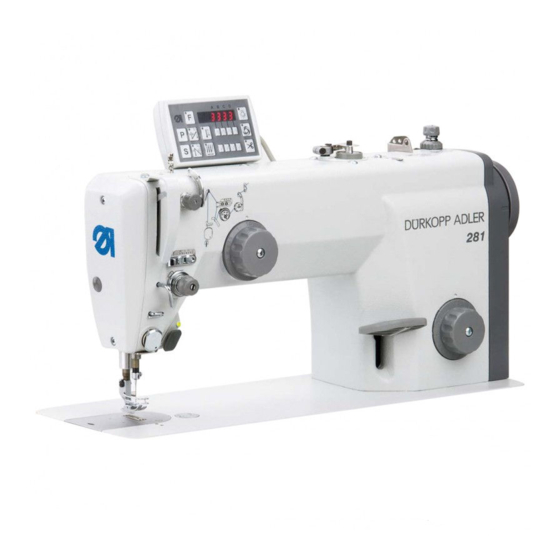
281
D
GB
CN
Teile-Nr./Part.-No.:
0791 281641
Advertisement
Table of Contents

Related Manuals for Duerkopp Adler 281


Summary of Contents for Duerkopp Adler 281
-
Page 1: Service Instructions
Spezialnähmaschine Serviceanleitung Service Instructions Service Instructions Manufacturer: Dürkopp Adler Manufacturing (Shanghai) Co., Ltd. 1201 Luoshan Road, Pudong New Area, Shanghai 200135, China Contact: Dürkopp Adler AG, PO Box 17 03 51, D-33703 Bielefeld, Potsdamerstr. 190, D-33719 Bielefeld, Phone +49 (0) 521 9 25 00, Fax +49 (0) 521 9 25 24 35, www.duerkopp-adler.com Manufacturer: Dürkopp Adler Manufacturing (Shanghai) Co., Ltd. - Page 2 Alle Rechte vorbehalten. Eigentum der Dürkopp Adler und urheberrechtlich geschützt. Jede, auch auszugsweise Wiederverwendung dieser Inhalte ist ohne vorheriges schriftliches Einverständnis der Dürkopp Adler verboten. All rights reserved. Property of Dürkopp Adler and copyrighted. Reproduction or publication of the content in any manner, even in extracts, without prior written permission of Dürkopp Adler, is prohibited.
-
Page 3: General Safety Instructions
General safety instructions The non-observance of the following safety instructions can cause bodily injuries or damages to the machine. 1. The machine must only be commissioned in full knowledge of the instruction book and operated by persons with appropriate training. 2. -
Page 5: Table Of Contents
Contents Page: Part 3: Service Instructions Class 281 (Edition 01/2009) General Tools and Gauges ..........Adjusting aids . - Page 6 Contents Page: Setting the bobbin winder Switching off the bobbin winder ........Winding form of the bobbin .
-
Page 7: General
General The present service instruction describes the adjustment of the special sewing machine 281. ATTENTION! The operations described in the service instructions must only be executed by qualified staff or correspondingly instructed persons respectively! Caution: Risk of injury ! In case of repair, alteration or maintenance work turn off the main switch and make sure to protect the machine from powering up accidentally. -
Page 8: Tools And Gauges
1.1 Tools and Gauges Size Figure Allen key Screw driver Flat tip 0.7 x 4,5 Flat tip 0.3 x 3 Flat tip 0.7 x 4.5 Cross tip B2 -H Open-end wrench Gauge Needle bar height 0281 801819 for needle diameter 1.62 mm Gauge Needle bar height 0281 800300... -
Page 9: Adjusting Aids
1.2 Adjusting aids The sewing machine can be locked in six different setting positions with the locking pin 1 and the arresting notches 2 on the arm shaft crank 3. The crank has six notches which are marked on the handwheel by the figures 1, 2, 3, 4, 5 and 6. -
Page 10: Feeding And Sewing Equipment
Feeding and sewing equipment 2.1 Timing of the thrust eccentric Caution: Risk of injury ! Turn the main switch off! Check and set the feed standstill only when the machine is switched off. ATTENTION! The thrust eccentric in the gear box 3 is already optimally set ex factory. -
Page 11: Timing Of The Lifting Cam
2.2 Timing of the lifting cam Caution: Risk of injury ! Turn the main switch off! Check and set the lifting cam only when the machine is switched off. Standard checking With the sewing machine arrested at locking position “2", align the notches 1 (of the lifting cam 2) and 4 (of the traction rod 5). -
Page 12: Feed Dog Height And Inclination
2.3 Feed dog height and inclination Fig. A Fig. B Standard checking Fig. A The emerging height of the feed dog over the throat plate, its angle of climb or the parallelism to the throat plate can be set via eccentrics 7 and 8. -
Page 13: Feed Dog Position Within The Throat Plate
Caution: Risk of injury ! Turn the main switch off! Check and set the feed dog height and inclination only with the sewing machine switched off. Correction feed dog height – Arrest the sewing machine at locking position “2". – Loosen screws 6 and 9. -
Page 14: Stitch Length Limitation
2.5 Stitch length limitation Caution: Risk of injury! Turn off the main switch! Check and set the stitch length limitation only with the sewing machine switched off. Standard checking The maximum stitch length for the sewing machine is 4.5 mm. With sewing equipment designed for smaller stitch length, the stitch length must also be limited accordingly, in order to avoid damaging the sewing machine or the sewing equipment. -
Page 15: Stitch Length Symmetry
2.6 Stitch length symmetry Caution: Risk of injury! Turn off the main switch! Check and set the stitch length symmetry only with the sewing machine switched off. Standard checking The forward and reverse stitch length (4.0 mm) are already set ex factory. -
Page 16: Sewing Foot Height And Sewing Foot Lifting
Sewing foot height and sewing foot lifting The maximum sewing foot lifting stroke amounts to: · 12 mm with machines with electromagnetic sewing foot lifting. · 14 mm with machines with knee lever. · 9 mm factory setting. 3.1 Pressure-bar height Caution: Risk of injury! Turn off the main switch! Check and set the pressure-bar height only with the sewing machine... -
Page 17: Mechanical Sewing Foot Lifting
3.2 Mechanical sewing foot lifting 3.2.1 Lifting motion and lifted sewing foot height Caution: Risk of injury! Turn off the main switch! Check and set the knee lever only with the sewing machine switched off. Standard checking With the sewing foot resting on the throat plate, before the lifting movement begins a lost motion should be perceptible at the knee lever. -
Page 18: Electromagnetic Sewing Foot Lifting
3.3 Electromagnetic sewing foot lifting 3.3.1 Sewing foot lifter solenoid position Caution: Risk of injury! Turn off the main switch! Check and set the sewing foot lifting only with the sewing machine switched off. Standard checking When operated, the anchor 2 of the solenoid 1 must always reach its internal final position, because its power consumption will be reduced to 30% after a sewing foot lifting. -
Page 19: Mounting The Sewing Foot Lifting Solenoid
3.3.2 Mounting the sewing foot lifting solenoid – Unscrew the handwheel 3, covering 2 and cover 1. – Unclamp the spring 4. – Loosen the screws 6 and remove the mounting flange 5. – Screw the holder 10 to the solenoid 8 using the screws 9 provided. –... - Page 20 18 17 – Tilt the machine head backwards. – Loosen screw 14. – Using the mounting aid 13, push the pre-assembled sewing foot lifting solenoid upwards in a way that the push rod 15 gets engaged in the upper guide bore hole. –...
-
Page 21: Replacing The Shock Absorbing Washer Of The Sewing Foot Lifter Solenoid
1 - 3 – Connect the cable of the sewing foot lifting solenoid to the terminal blocks, one wire to one of the terminal from 1 to 3 and the second one to the terminal 5. – If necessary, set the sewing foot height anew (see chapter 3.3.1). –... -
Page 22: Sewing Foot Pressure
3.4 Sewing foot pressure Standard checking The figures on the setting wheel 1 gives the sewing foot pressure in “N”. (1kp = approx. 10N). The required sewing foot pressure depends on the following parameters: · Sewing speed · Damping characteristics of the material to be sewn ·... -
Page 23: Thread-Guiding Parts
Thread-guiding parts 4.1 Releasing the needle thread tension Caution: Risk of injury! Turn off the main switch! Check and set the releasing of the needle thread tension only when the machine is switched off. Standard checking Pressing on the axle 3 opens the thread tensioner by approx. 1 mm. With the thread tensioner closed and with no thread between the tension discs the axle 3 should have a clearance of approx. -
Page 24: Thread Take-Up Spring
4.2 Thread take-up spring Caution: Risk of injury! Turn off the main switch! Check and set the thread take-up spring only with the sewing machine switched off. Standard checking The thread take-up spring 2 should keep the needle thread under tension at least until the needle point has penetrated the material to be sewn. -
Page 25: Thread Regulator
4.3 Thread regulator Caution: Risk of injury! Turn off the main switch! Check and set the thread regulator only when the machine is switched off. Standard checking The setting of the thread regulator 2 depends on: · Material thickness · Thread size ·... -
Page 26: Needle Bar Height
Needle bar height Caution: Risk of injury! Turn off the main switch! Check and set the needle bar height only with the sewing machine switched off. ATTENTION RISK OF BREAKAGE! It is not permitted to fix an adjusting block on the needle bar of the class 281. -
Page 27: Hook Setting
Hook setting 6.1 Looping stroke and distance between the hook point and needle Caution: Risk of injury! Turn off the main switch! Check and set the looping stroke and the distance between the hook point and needle only with the sewing machine switched off. Standard checking The loop stroke is the distance covered by the needle bar from the bottom dead center up to the point where the hook tip 2 coincides with... -
Page 28: Bobbin Case Support
6.2 Bobbin case support Caution: Risk of injury! Turn off the main switch! Check and set the bobbin case support only with the sewing machine switched off. Standard checking The bobbin case support is factory set. After a replacement of the support, the new support may eventually need to be adjusted. -
Page 29: Thread Trimmer
Thread trimmer The control cam 3 determines the stroke and the timing of the knife motion. The timing thus coincides with the motion of the needle. The thread trimmer is switched on electromagnetically. 7.1 Control cam for the knife motion 7.1.1 Control cam position Caution: Risk of injury! -
Page 30: Distance Between The Roller And Thread Trimmer Cam
7.1.2 Distance between the roller and thread trimmer cam Caution: Risk of injury! Turn off the main switch. Check and set the control cam only with the sewing machine switched off. Standard checking At the external end position of the thread trimmer lever 5 there should be a distance of 0,2 + 0,1 mm between the external diameter of the control cam 3 and the roller 1. -
Page 31: Hooked Knife
7.2 Hooked knife Caution: Risk of injury! Turn off the main switch. Check and set the hooked knife only with the sewing machine switched off. Standard checking The hooked knife 2 must lie against both screws 1 in the direction of the arrow. -
Page 32: Setting The Cutting Pressure
7.3 Setting the cutting pressure Caution: Risk of injury! Turn off the main switch. Check and set the cutting pressure only with the sewing machine switched off. When performing setting tasks within the hook area, both knives should preferably remain in the machine. Thus avoiding unnecessary adjustment work. -
Page 33: Setting The Bobbin Winder
Setting the bobbin winder 8.1 Switching off the bobbin winder Caution: Risk of injury! Turn the main switch off! Check and set the bobbin winder only with the sewing machine switched off. Standard checking The bobbin winder should stop automatically, when the bobbin is filled up to approx. -
Page 34: Winding Form Of The Bobbin
8.2 Winding form of the bobbin Caution: Risk of injury! Turn the main switch off! Check and set the bobbin winder only with the sewing machine switched off. Standard checking The winding form depends on the position of the gap 3 between both thread guide sleeves. -
Page 35: Filling Up Oil (Gear Box)
Filling up oil (gear box) Caution: Risk of injury! Oil can cause skin eruptions. Avoid protracted contact with the skin. In event of contact, thoroughly wash the affected area. ATTENTION ! The handling and disposal of mineral oils is subject to legal regulation. Deliver used oil to an authorised collection point. -
Page 36: Hook Lubrication
10. Hook lubrication (only subclasses with oil lubricated hook) Caution: Risk of injury! Oil can cause skin eruptions. Avoid protracted contact with the skin. In event of contact, thoroughly wash the affected area. ATTENTION ! The handling and disposal of mineral oils is subject to legal regulation. Deliver used oil to an authorised collection point. -
Page 37: Setting The Oil Quantity For The Hook
10.1 Setting the oil quantity for the hook The hook lubrication is insured by the oil wick inside a silicone rubber hose, going from the hook oil reservoir to the spray cone on the back of the hook. The oil quantity can be reduced through the adjustment screw 1. By pressing the hose, the adjustment screw throttles the oil quantity for the hook. -
Page 38: Maintenance
11. Maintenance Caution: Risk of injury! Turn the main switch off! The maintenance of the sewing machine must only be done when the machine is switched off. The daily or weekly maintenance work (cleaning and oiling) to be carried out by the operators of the sewing machine is described in the operating instructions (part 1).
Need help?
Do you have a question about the 281 and is the answer not in the manual?
Questions and answers