Table of Contents
Advertisement
Advertisement
Table of Contents

Related Manuals for Samson MDR1064


Summary of Contents for Samson MDR1064
- Page 1 TEN CHANNEL MIXER...
- Page 2 Safety Instructions/Consignes de sécurité/Sicherheitsvorkehrungen/Instrucciones de seguridad WARNING: To reduce the risk of fire or electric shock, do not expose this unit to ATTENTION: Pour éviter tout risque d’électrocution ou d’incendie, ne pas rain or moisture. To reduce the hazard of electrical shock, do not remove cover or exposer cet appareil à...
-
Page 3: Table Of Contents
Operating the MDR1064 12–14 System Set-ups 15–16 MDR1064 Wiring Guide Specifications Block Diagram Notes Copyright 2004, Samson Technologies Corp. Printed February, 2004 Samson Technologies Corp. 575 Underhill Blvd. P.O. Box 9031 Syosset, NY 11791-9031 Phone: 1-800-3-SAMSON (1-800-372-6766) Fax: 516-364-3888 www.samsontech.com... -
Page 4: Introduction
Should your unit ever require servicing, a Return Authorization number (RA) must be obtained before shipping your unit to Samson. Without this number, the unit will not be accepted. Please call Samson at 1-800-3SAMSON (1-800-372-6766) for a Return Authorization number prior to shipping your unit. Please retain the original packing... -
Page 5: Mdr1064 Features
MDR1064 Features The Samson MDR1064, ten-channel mixer is a comprehensive, all-in-one solution for live sound, recording, fixed installation and post production applications. Here are some of its main features: • Eight Channels – Six Mic/Line plus two Stereo inputs with mic pre’s. -
Page 6: Front And Rear Panel Layout
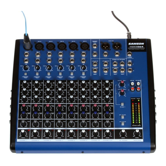
Front and Rear Panel Layout... -
Page 7: Front And Rear Panel Controls
Front and Rear Panel Controls 20 AUX SEND 1 – Line level output from the Auxiliary 1 FRONT PANEL bus. MIC IN – Input connector for Low-Noise Microphone pre- 21 AUX SEND 2 – Line level output from the Auxiliary 2 amp. -
Page 8: Controls And Functions
Controls and Functions MONO/STEREO INPUT CHANNEL SECTION The following section details each part of the MDR1064’s MONO INPUT CHANNELS including the GAIN con- trol, LOW CUT switch, 3-BAND EQ, AUX sends, PEAK LED, PAN and LEVEL controls. The input channels one through six on the MDR1064 feature high quality, discrete transistor pre-amp providing transparency and extended dynamic range. - Page 9 Controls and Functions (MONO/STEREO INPUT CHANNEL CONTINUED) NOTE: The channel’s AUX 2 signal is sent to the AUX 2 bus from a location in the signal path after the channel’s LEVEL control. This is commonly referred to as a POST FADER send. This means that the amount of signal that is sent to the AUX 2 bus will be affected not only by the setting of the AUX 2 knob control, but it will also be affected by the setting of the LEVEL control.
-
Page 10: Master Section
Controls and Functions MASTER SECTION MAIN LEVEL The master MAIN control is the overall volume control for the left and right mix bus. These line level signals are output from the MAIN MIX jacks. PHONES / CR The PHONES / CR control is used to set the level sent to the control room outputs, and also to the headphone jack. - Page 11 Controls and Functions MASTER SECTION (continued) AUX RET 2 The AUX RETURN 2 adjusts the level of the signal present at the AUX 2 RET jacks. This signal is summed, or mixed in to the main L/R MIX bus. TO AUX 1 This routes the signal that is present on the AUX 2 RETURN jacks to AUX 1 so that the effects can be heard in the monitor mix.
-
Page 12: Mdr1064 Input And Output Connections
MDR1064 Input and Output Connections CHANNEL 1 – 6 MIC and LINE INPUTS The MDR1064’s channel 1 through 6 mono inputs each have a 1/4-inch connector for line level signals and XLR connectors for the MIC signals. Channels 7/8 and 9/10 stereo inputs each have 1/4-inch connectors for line level inputs. -
Page 13: Mdr1064 Input And Output Connections
MDR1064 Input and Output Connections MAIN MIX LEFT/RIGHT XLR OUTPUTS In a live sound application, the LEFT/ RIGHT MIX outputs are connected to a power amplifier or powered speak- ers. In a recording application, the LEFT/ RIGHT MIX outputs are used to connect to the inputs of a stereo device such as computer sound card, DAT, or cassette recorder. -
Page 14: Operating The Mdr1064
Operating the MDR1064 BASIC OPERATION The following section explains the basic operation of the MDR1064. CONNECTING MICROPHONES AND INSTRUMENTS 1. Before connecting mics or instruments, make sure that the power of all your systems components including the MDR1064 is turned off. Also, make sure that the MAIN LEVEL and PHONES / CR controls are turned all the way down. - Page 15 This allows you to create a mix for the monitors that is independent of the main LEFT and RIGHT MIX. 2. In order to get the most gain from your monitor mix, use an external graphic equalizer (like a Samson S curve 131) to cut out any frequencies that cause feedback.
-
Page 16: Operating The Mdr1064
Operating the MDR1064 USING AN EXTERNAL EFFECT If you prefer to use an external device for effects process- ing, you can easily connect the unit using the MDR1064 AUX 2 bus. Follow the simple steps below to interface your processor: 1. -
Page 17: System Set-Ups
MDR1064 System Set-Ups MDR1064 LIVE SOUND SET-UP... - Page 18 MDR1064 System Set-Ups MDR1064 RECORDING SET-UP...
-
Page 19: Mdr1064 Wiring Guide
MDR1064 Wiring Guide CONNECTING THE MDR1064 The are several ways to interface the MDR1064 to support a variety of applications. The MDR1064 features bal- anced inputs and outputs, so connecting balanced and unbalanced signals is possible. Unbalanced 1/4” Connector Balanced TRS 1/4” Connector XLR Balanced Wiring Guide 1/4-inch TRS “Y”... -
Page 20: Specifications
MDR1064 Specifications Mono input channels Microphone input electronically balanced, discrete input con- figuration Frequency response 10Hz to 45kHz Distortion (THD & N) 0.005% at 4dBu, 1kHz Gain range 0dB to +40dB (MIC) SNR (Signal to Noise Ratio) 105dB Line input electronically balanced Frequency response 10Hz to 45kHz... -
Page 21: Block Diagram
MDR1064 Block Diagram... -
Page 22: Notes
Notes... - Page 24 Samson Technologies Corp. 575 Underhill Blvd. P.O. Box 9031 Syosset, NY 11791-9031 Phone: 1-800-3-SAMSON (1-800-372-6766) Fax: 516-364-3888 www.samsontech.com...
Need help?
Do you have a question about the MDR1064 and is the answer not in the manual?
Questions and answers
How many volts I must use and what indicates that the mixer Is powerd on
The Samson MDR1064 mixer requires different voltages based on the region:
- USA/Canada: 108 - 132V, 60Hz
- Europe: 210 - 230V, 50Hz
- U.K./Australia: 240V, 50Hz
You can tell if the mixer is powered on by checking the Phantom Power LED and the Output Level Meter. The Phantom Power LED lights up when the 48V phantom power is enabled, and the Output Level Meter displays the signal level being sent to the MIX OUT jacks.
This answer is automatically generated