Integra DTR-7.8 Instruction Manual
Av
Hide thumbs
Also See for Integra DTR-7.8:
- Instruction manual (128 pages) ,
- Service manual (339 pages) ,
- Service manual (339 pages)
Table of Contents
Advertisement
Quick Links
Advertisement
Chapters
Table of Contents

Subscribe to Our Youtube Channel
Related Manuals for Integra Integra DTR-7.8


Summary of Contents for Integra Integra DTR-7.8
- Page 1 AV Receiver DTR-7.8 Instruction Manual...
-
Page 2: Important Safety Instructions
Thank you for purchasing an Integra AV Receiver. Please read this manual thoroughly before making connections and plugging in the unit. Following the instructions in this manual will enable you to obtain optimum performance and listening enjoyment from your new AV Receiver. Please retain this manual for future reference. - Page 3 Precautions 1. Recording Copyright —Unless it’s for personal use For U.S. models only, recording copyrighted material is illegal with- FCC Information for User out the permission of the copyright holder. CAUTION: 2. AC Fuse —The AC fuse inside the unit is not user- The user changes or modifications not expressly serviceable.
- Page 4 We, ONKYO EUROPE ELECTRONICS GmbH LIEGNITZERSTRASSE 6, 82194 GROEBENZELL, GERMANY declare in own responsibility, that the ONKYO product described in this instruction manual is in compliance with the corresponding technical standards such as EN60065, EN55013, EN55020 and EN61000-3-2, -3-3. GROEBENZELL, GERMANY K.
-
Page 5: Table Of Contents
Connecting the Power Cords of Other Components Zone 2/Zone 3 Out Settings ........114 (North American model only) .........41 Using Zone 2 and Zone 3 ......... 114 Connecting Integra/Onkyo Components ....42 Using the 12V Triggers ........... 117 Connecting the Power Cord ........42 Using the Remote Controller in Zone 2/3 Turning On the AV Receiver ...... -
Page 6: Features
• HDMI upconversion of composite video, S-Video, and component video sources (720p capable) • Component video upconversion of composite video Theater-Dimensional is a trademark of Onkyo Corporation. and S-Video sources *6 Re-Equalization and the “Re-EQ” logo are trademarks of THX •... -
Page 7: Supplied Accessories
Supplied Accessories Features —Continued Make sure you have the following accessories: ©2005 SIRIUS Satellite Radio Inc. “SIRIUS,” SiriusConnect, the SIRIUS dog logo, channel names and logos are trademarks of SIRIUS Satellite Radio Inc. Available only in the contiguous United States (excluding Alaska and Hawaii) and Canada. Remote controller and three batteries (AA/R6) Manufactured under license from Audyssey Laboratories. -
Page 8: Multiroom Capability
Multiroom Capability You can use three speaker systems with this AV receiver —a surround-sound speaker system (up to 7.1 channels) in your main listening room, a stereo speaker system in a second room, or Zone 2, as we call it, and another stereo speaker system in a third room that we call Zone 3 (external power amplifier required). -
Page 9: Getting To Know The Av Receiver
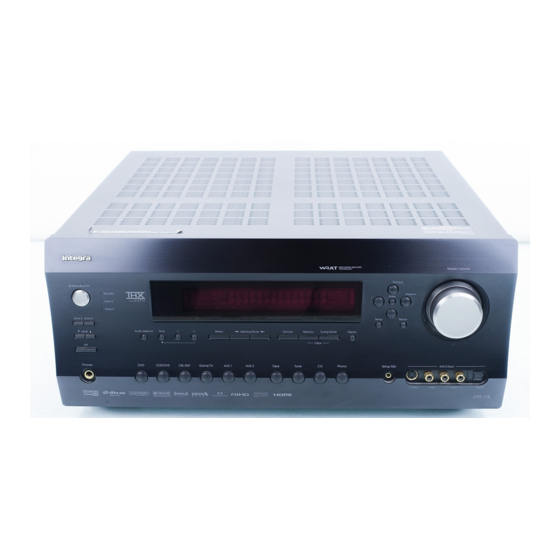
Getting to Know the AV Receiver Front Panel North American model J K L M N Other models The actual front panel has various logos printed on it. They are not shown here for clarity. For detailed information, see the pages in parentheses. Standby/On button (43) Ready indicator (109) Sets the AV receiver to On or Standby. - Page 10 Getting to Know the AV Receiver —Continued Zone 3 indicator (115) Phones jack (80) Flashes when Zone 3 is being set. Lights up when This 1/4-inch phone jack is for connecting a stan- Zone 3 is on. dard pair of stereo headphones for private listening. Remote-control sensor (14) Audio Selector button (81) Receives control signals from the remote controller.
-
Page 11: Display
Getting to Know the AV Receiver —Continued Display For detailed information, see the pages in parentheses. Speaker/channel indicators (87) Headphone indicator (80) Indicate the speaker configuration and channels Lights up when a pair of headphones are plugged used by the current input source. into the PHONES jack. -
Page 12: Rear Panel
-capable Inte- The HDMI inputs are for connecting components gra/Onkyo component for remote and system with an HDMI output, such as a DVD player, DVD control. recorder, or DVR (digital video recorder). They’re To use... - Page 13 Getting to Know the AV Receiver —Continued IR IN A/B and OUT CBL/SAT IN A commercially available IR receiver can be con- A cable or satellite receiver can be connected here. nected to the IR IN A or B jack, allowing you to There’s S-Video and composite video input jacks control the AV receiver while you’re in Zone 2, or for connecting the video signal.
-
Page 14: Remote Controller
Remote Controller Installing the Batteries Using the Remote Controller When using the remote controller, point it toward the AV To open the battery compartment, press receiver’s remote control sensor, as shown below. the small hollow and slide open the cover. Remote control sensor Standby indicator AV receiver... -
Page 15: About The Remote Controller Modes
As well as the AV receiver, you can also use the remote Receiver/Tape mode is used to control the AV receiver. controller to control your other AV components. The It can also be used to control an Onkyo cassette recorder remote controller has a specific operating mode for use connected via with each type of component. - Page 16 Remote Controller —Continued For detailed information, see the pages in parentheses. L Night button (91) Turns the Late Night function on or off. Standby button (43) Audio Sel button (81) Sets the AV receiver to Standby. Selects the audio input: analog, digital, HDMI, or multichannel.
-
Page 17: Dvd Mode
Remote Controller —Continued Standby button DVD Mode Sets the DVD player to Standby. To set the remote controller to DVD mode, press the On button [DVD] Remote Mode button. Turns on the DVD player. Number buttons Used to enter title, chapter, and track numbers, and to enter times for locating specific points. -
Page 18: Cd/Md/Cdr Modes
[CD] Remote Mode button to select the Used to enter track numbers and times for locating CD/MD/CDR remote controller mode. specific points. In order to control an Onkyo MD recorder or CD recorder, or a component made by another manufacturer, Arrow [ ] and Enter buttons you must first enter the appropriate remote control code... -
Page 19: Dock Mode
Remote Controller —Continued Standby button Dock Mode Turns off the iPod. Dock mode is for controlling an Apple iPod in an Onkyo On button* RI Dock that’s connected via Turns on the iPod. When Using an RI Dock: Top Menu button •... -
Page 20: Connecting Your Speakers
You can enjoy DVDs featuring Dolby Digital or DTS. With analog or digital TV, you can enjoy Dolby Pro Logic IIx, DTS Neo:6, or Onkyo’s original DSP listening modes. -
Page 21: Connecting Your Speakers
Connecting Your Speakers —Continued Connecting a Powered Subwoofer Connecting Your Speakers Using a suitable cable, connect the AV receiver’s SUB- Speaker Configuration WOOFER PRE OUT to the input on your powered sub- woofer. If your subwoofer is unpowered and you’re For the best surround-sound experience, you should con- using an external amplifier, connect the SUBWOOFER nect seven speakers and a powered subwoofer. - Page 22 Connecting Your Speakers —Continued Speaker Connection Precautions Read the following before connecting your speakers: • Unnecessarily long or very thin speaker cables may affect the sound quality and should be avoided. • You can connect speakers with an impedance of •...
-
Page 23: Bi-Amping The Front Speakers
Connecting Your Speakers —Continued Bi-amping Speaker Hookup Bi-amping the Front Speakers The FRONT L/R and SURR BACK L/R terminal posts Connect the AV receiver’s FRONT R positive (+) can be used with front speakers and surround back terminal to the right speaker’s positive (+) tweeter speakers respectively, or bi-amped to provide separate (high) terminal. -
Page 24: Connecting Antennas
Connecting Antennas This section explains how to connect the supplied indoor If you cannot achieve good reception with the supplied FM antenna and AM loop antenna, and how to connect indoor FM antenna, try a commercially available out- commercially available outdoor FM and AM antennas. door FM antenna instead (see page 25). -
Page 25: Connecting An Outdoor Fm Antenna
Connecting Antennas —Continued Connecting an Outdoor FM Antenna Connecting an Outdoor AM Antenna If you cannot achieve good reception with the supplied If good reception cannot be achieved using the supplied indoor FM antenna, try a commercially available out- AM loop antenna, an outdoor AM antenna can be used in door FM antenna instead. -
Page 26: Connecting Your Components
Connecting Your Components AV Connection Color Coding About AV Connections RCA-type AV connections are usually color coded: red, • Before making any AV connections, read the manuals white, and yellow. Use red plugs to connect right- supplied with your other AV components. channel audio inputs and outputs (typically labeled “R”). -
Page 27: Connecting Audio And Video Signals To The Av Receiver
Connecting Your Components —Continued Connecting Audio and Video Signals to the AV Receiver By connecting both the audio and video outputs of your DVD player and other AV components to the AV receiver, you can switch the audio and video signals simultaneously simply by changing the input source on the AV receiver. : Signal Flow Video Video... - Page 28 Connecting Your Components —Continued ■ HDMI Monitor Setting Set to No With the HDMI Monitor setting set to No (see Video Signal Flow Chart page 45), video input signals flow through the DVD player, etc. AV receiver as shown, with composite video and S-Video sources being upconverted for the component video output.
-
Page 29: Connecting A Tv Or Projector
Connecting Your Components —Continued Connecting a TV or Projector Step 1: Video Connection Choose a video connection that matches your TV ( , , or ), and then make the connection. Step 2: Audio Connection Choose an audio connection that matches your TV ( , , or ), and then make the connection. -
Page 30: Connecting A Dvd Player
Connecting Your Components —Continued Connecting a DVD player Step 1: Video Connection Choose a video connection that matches your DVD player ( , , or , and then make the connection. If you use connection , you must connect the AV receiver to your TV with the same type of connection. Step 2: Audio Connection Choose an audio connection that matches your DVD player ( , , or... - Page 31 Connecting Your Components —Continued Hooking Up the Multichannel Input If your DVD player supports multichannel audio formats such as DVD-Audio and SACD, and it has a multichannel analog audio output, you can connect it to the AV receiver’s multichannel input. Use a multichannel analog audio cable, or several normal audio cables, to connect the AV receiver’s MULTI CH FRONT L/R, CENTER, SURR L/R, SURR BACK L/R, and SUBWOOFER jacks to the 7.1-channel analog audio output on your DVD player.
-
Page 32: Connecting A Vcr Or Dvr For Playback
Connecting Your Components —Continued Connecting a VCR or DVR for Playback With this hookup, you can use the tuner in your VCR or DVR to listen to your favorite TV programs Hint! via the AV receiver, which is useful if your TV has no audio outputs. Step 1: Video Connection Choose a video connection that matches your VCR or DVR ( , , or... -
Page 33: Connecting A Vcr Or Dvr For Recording
Connecting Your Components —Continued Connecting a VCR or DVR for Recording Step 1: Video Connection Choose a video connection that matches your VCR or DVR ( ), and then make the connection. The video source to be recorded must be connected to the AV receiver via the same type of connection. Step 2: Audio Connection Choose an audio connection that matches your VCR or DVR ( ), and then make the connection. -
Page 34: Connecting A Satellite, Cable, Or Terrestrial Set-Top Box Or Other Video Source
Connecting Your Components —Continued Connecting a Satellite, Cable, or Terrestrial Set-top box or Other Video Source With this hookup, you can use your satellite or cable receiver to listen to your favorite TV programs Hint! via the AV receiver, which is useful if your TV has no audio outputs. Step 1: Video Connection Choose a video connection that matches the video source ( , , or... -
Page 35: Connecting Components With Hdmi
Connecting Your Components —Continued Connecting Components with HDMI About HDMI Designed to meet the increased demands of digital TV, HDMI (High Definition Multimedia Interface) is a new digital interface standard for connecting TVs, projectors, DVD players, set-top boxes, and other video components. Until now, several separate video and audio cables have been required to connect AV components. -
Page 36: Audio Signals
Connecting Your Components —Continued Making HDMI Connections Step 1: Use HDMI cables to connect the AV receiver’s HDMI jacks to your HDMI-compatible DVD player, TV, projector, and so on. Step 2: Assign each HDMI IN to an input selector. See “HDMI Input Setup” on page 46. ■... -
Page 37: Connecting A Game Console
Connecting Your Components —Continued Connecting a Game Console Step 1: Video Connection Choose a video connection that matches your game console ( , , or , and then make the connection. If you use connection , you must connect the AV receiver to your TV with the same type of connection. Step 2: Audio Connection Choose an audio connection that matches your DVD player ( , , or... -
Page 38: Connecting A Camcorder Or Other Av Component
Connecting Your Components —Continued Connecting a Camcorder or Other AV Component Step 1: Video Connection Choose a video connection that matches your camcorder ( ), and then make the connection. Step 2: Audio Connection Choose an audio connection that matches your camcorder ( ), and then make the connection. -
Page 39: Connecting A Cd Player
Connecting Your Components —Continued Connecting a CD Player Step 1: Choose a connection that matches your CD player ( , , or ), and then make the connection. HDMI AC INLET ASSIGNABLE IN 3 IN 2 IN 1 RS232 ETHERNET ANTENNA MONITOR OUT 2 COMPONENT VIDEO... -
Page 40: Connecting A Cassette, Cdr, Minidisc, Or Dat Recorder
Connecting Your Components —Continued Connecting a Cassette, CDR, MiniDisc, or DAT Recorder Step 1: Choose a connection that matches your recorder ( , , or ), and then make the connection. COAXIAL HDMI AC INLET ASSIGNABLE IN 2 IN 3 IN 2 IN 1 RS232... -
Page 41: Connecting An Ri Dock
Bi-AMP GAME/TV IN 2 (CD) If you have an Onkyo DS-A1 RI Dock, connect its video output jack to the AV receiver’s GAME/TV IN S jack. Notes: • Connect the RI Dock to the AV receiver with an cable (see page 42). -
Page 42: Connecting Integra/Onkyo Components
Connecting Your Components —Continued Connecting Integra/Onkyo Components Step 1: Make sure that each Integra/Onkyo component is connected to the AV receiver with an analog audio cable (RCA). Step 2: Make the necessary connections (see illustration below). Step 3: If you’re using an MD, CDR, or RI DOCK component, change the Input Display (see page 49). -
Page 43: Turning On The Av Receiver
Input Setup” on page 48, or “Digital Input Setup” on page 50 respec- OPTICAL tively. ■ Did you connect an Onkyo MD recorder, CD recorder, or RI Dock? If you did, see “Changing the Input Display” on page 49. MD recorder, CD recorder,... -
Page 44: First Time Setup
First Time Setup This section explains the settings that you need to make before using the AV receiver for the very first time. Speaker Settings Use the Up and Down [ buttons to select “1. Speaker Set- AUX 1 AUX 2 TV CH Game tings,”... -
Page 45: Hdmi Monitor Setup
First Time Setup —Continued HDMI Monitor Setup Use the Up and Down [ buttons to select “1. Input/Output Assign,” and then press [Enter]. Enter The Input/Output Assign menu appears. Standby Input TV CH Game AUX 1 AUX 2 Enter Tape Tuner TV VOL Phono... -
Page 46: Hdmi Input Setup
First Time Setup —Continued HDMI Input Setup Use the Up and Down [ buttons to select “Monitor Out2,” and use the Left and Right Tape Tuner ] buttons to select: TV VOL Phono D.TUN Monitor: Select this if you’ve con- Clear --/--- 10 Input Selector... - Page 47 First Time Setup —Continued Notes: Press the [Receiver] button, fol- • Each HDMI IN cannot be assigned to more than one lowed by the [Setup] button. Receiver input selector. The main menu appears onscreen. • For composite video, S-Video, and component video upconversion for the HDMI OUT, the HDMI Monitor setting must be set to Yes (see page 45).
-
Page 48: Component Video Input Setup
First Time Setup —Continued Component Video Input Setup Press the [Receiver] button, fol- lowed by the [Setup] button. Receiver The main menu appears onscreen. Standby Input AUX 1 AUX 2 TV CH Game Use the Up and Down [ Tape Tuner buttons to select “1. -
Page 49: Changing The Input Display
Press the [Setup] button. Setup closes. If you connect an -capable Onkyo MiniDisc recorder, CD recorder, or RI Dock to the TAPE IN/OUT jacks, or connect an RI Dock to the GAME/TV jacks, for to work properly, you must change this setting. -
Page 50: Digital Input Setup
First Time Setup —Continued Digital Input Setup Use the Up and Down [ buttons to select “1. Input/Output Assign,” and then press [Enter]. Enter The Input/Output Assign menu appears. Standby Input TV CH Game AUX 1 AUX 2 Enter Tape Tuner TV VOL Phono... - Page 51 First Time Setup —Continued Press the [Setup] button. Setup closes. Notes: • Only FRONT can be assigned to the AUX 2 input selector. • The TUNER input selector cannot be assigned and is fixed at the “- - -” option. •...
-
Page 52: Analog Input Setup
First Time Setup —Continued Analog Input Setup Use the Up and Down [ buttons to select “5. Analog Input,” and then press [Enter]. Enter The Analog Input menu appears. Standby 1-5.Analog Input Input Multich AUX 1 AUX 2 TV CH Game Enter Tape... -
Page 53: Automatic Speaker Setup (Audyssey Multeq Xt)
First Time Setup —Continued Using Audyssey MultEQ XT Automatic Speaker Setup (Audyssey MultEQ XT) Notes: With the supplied speaker setup microphone, Audyssey • If any of your speakers is 4 ohms, change the MultEQ XT can measure the number of speakers con- Speaker Impedance setting before running the nected, their sizes, crossover frequencies, and distances automatic speaker setup (see page 44). - Page 54 First Time Setup —Continued Turn on the AV receiver and the The speaker detect results connected TV. appear. On the TV, select the input to which the AUDYSSEY Auto Speaker Setup Enter AV receiver is connected. -----SP Detect Result----- FL : Yes FR : Yes Place the setup microphone at SL : Yes...
- Page 55 First Time Setup —Continued After the 6th or 7th measurement, the Review SP Distance: Review the following screen appears. speaker distance settings (see “Reviewing the Results” on AUDYSSEY Auto Speaker Setup Enter page 57). Review SP Level: Review the speaker Please select “Next”, when measuring next position, and select “finish”, level settings (see “Reviewing...
- Page 56 First Time Setup —Continued Speaker Detect Error AUDYSSEY Auto Speaker Setup AUDYSSEY Auto Speaker Setup -----Speaker Detect Error----- -----Speaker Detect Error----- FL : Error FR : Yes FL : Yes FR : Yes SL : Yes SR : Yes SL : Yes SR : Yes SBL : Yes SBR : Yes...
- Page 57 First Time Setup —Continued Changing the Speaker Settings Manually Reviewing the Results In some cases, the measurements taken by the automatic Use the Up and Down [ speaker setup may not provide usable results. If running buttons to select the settings that the speaker setup a second time doesn’t help, you’ll have you want to review, and then Enter...
-
Page 58: Tv Format Setup (Not North American Models)
First Time Setup —Continued TV Format Setup Use the Up and Down [ (not North American models) buttons to select “2. OSD Setup,” and then press [Enter]. Enter The OSD Setup menu appears. 6-2.OSD Setup Immidiate Display Standby Monitor Type Input Display Position Bottom... -
Page 59: Am Frequency Step Setup(On Some Models)
First Time Setup —Continued AM Frequency Step Setup Use the Up and Down [ (on some models) buttons to select “3. Tuner,” and then press [Enter]. Enter The Tuner menu appears. 7-3.Tuner AM Freq Step 9kHz Standby Input Enter TV CH AUX 1 AUX 2 Game... -
Page 60: Playing Your Av Components
Playing Your AV Components Basic AV Receiver Operation Standby Input AUX 1 AUX 2 TV CH Game Tape Tuner TV VOL Phono D.TUN Clear --/--- 10 Input Selector Macro Zone 3 Remote Mode Zone 2 CDR/MD Cable Dock Receiver Tape/AMP Dimmer Sleep Enter... -
Page 61: Listening To The Radio
Listening to the Radio ■ Manual Tuning Mode Listening to AM/FM Stations Press the [Tuning Mode] button so that the AUTO indicator disap- Tuning Mode pears from the display. Tuning Press and hold the Tuning Up or Down [ ]/[ ] button. The frequency stops changing when you release the button. - Page 62 Listening to the Radio —Continued ■ Tuning into Stations by Frequency Displaying AM/FM Radio Information You can tune into AM and FM stations directly by enter- ing the appropriate frequency. Display Standby Input Number buttons TV CH Game AUX 1 AUX 2 Tape Tuner...
-
Page 63: Using Rds (Not North American Model)
Listening to the Radio —Continued Using RDS (not North American model) RDS only works in areas where RDS broadcasts are RDS Program Types (PTY) available. When tuned to an RDS station, the RDS indi- Type Display cator appears. None NONE RDS indicator News reports NEWS... - Page 64 Listening to the Radio —Continued Displaying Radio Text (RT) To start the search, press [Enter]. The AV receiver searches until it finds a RT/PTY/TP station of the type you specified, at which point it stops briefly before con- tinuing with the search. When a station you want to listen to is found, press [Enter].
-
Page 65: Listening To Xm Satellite Radio (North American Model Only)
Listening to the Radio —Continued Connecting the XM Mini-Tuner and Home ® Listening to XM Satellite Radio Dock (North American Model Only) To receive XM Satellite Radio, you need an XM Mini- Tuner and Home Dock, which includes a home antenna. Important XM Radio Information These are sold separately. - Page 66 Listening to the Radio —Continued Use the Up and Down [ buttons to select “3. Tuner,” and then press [Enter]. Standby Input Enter The Tuner screen appears. Number buttons TV CH Game AUX 1 AUX 2 7-3.Tuner Tape Tuner Satellite Radio None TV VOL Phono...
- Page 67 Listening to the Radio —Continued ■ Category Search Mode To sign up, go to: Press the [Receiver] Remote http://activate.xmradio.com Mode button, and then press the Or call: 1-800-967-2346 Receiver [Enter] button repeatedly to For XM Canada, go to: select Category Search mode. http://xmradio.ca Or call: 1-877-438-9677 Enter...
- Page 68 Listening to the Radio —Continued Displaying XM Radio Information Tuning Memory AV receiver Enter Return Press the [Display] button repeatedly to cycle through the available information. Remote controller Display Tuning Mode The following information can be displayed: Display Channel name ↓...
- Page 69 Listening to the Radio —Continued ❑ UPDATING Use the Up and Down [ XM is updating your Mini-Tuner with the latest buttons to select “4. Satellite encryption code. Wait a few seconds until the update Radio,” and then press [Enter]. is done.
-
Page 70: Listening To Sirius Satellite Radio ® (North American Models Only)
Listening to the Radio —Continued ® Listening to SIRIUS Satellite Radio Indoor/outdoor antenna (North American Models Only) with 21-foot cable Important SIRIUS Satellite Radio Information SiriusConnect AC power receiver SIRIUS is available in the US for subscribers with addresses in the continental US and is available in Canada for subscribers with a Canadian address. - Page 71 Listening to the Radio —Continued Use the Up and Down [ Enter Tuning buttons to select “3. Tuner,” and then press [Enter]. Enter The Tuner screen appears. 7-3.Tuner Satellite Radio None Enter Tuner Setup Use the Left and Right [ buttons to select “SIRIUS.”...
- Page 72 Listening to the Radio —Continued ■ Channel Search Mode Signing Up for SIRIUS Satellite Radio Before you can use SIRIUS Satellite Radio, you must Press the [Receiver] Remote first sign up for an account. You’ll need a major credit Receiver Mode button, and then press the card and your SIRIUS Satellite Radio ID, which you can [Enter] button repeatedly to...
- Page 73 Listening to the Radio —Continued Parental Lock Within 8 seconds, use the num- ber buttons to enter the channel With SIRIUS Parental Lock, you can lock out channels number. that you do not want to receive and use a 4-digit PIN For example, to select channel #20, number to prevent others from unlocking them.
- Page 74 Listening to the Radio —Continued Press the [Setup] button. Press the [D.TUN] button, and Setup closes. then use the number buttons to enter the 4-digit PIN number. D.TUN Clear Notes: Use the Left and Right [ • While a channel is locked, it cannot be selected for buttons to select a number on the listening.
- Page 75 Use the Up and Down [ Use the Up and Down [ buttons to select “4. Source buttons to select “Edit Code,” Setup,” and then press [Enter]. and then press [Enter]. Enter Enter The Source Setup menu appears. The New Code screen appears. 4-5.SIRIUS Parental Lock 4.Source Setup 1.IntelliVolume...
- Page 76 Listening to the Radio —Continued Tuning Positioning the SiriusConnect Home Enter Antenna You can check the strength of the SIRIUS Satellite Radio signal and adjust the position of the SiriusConnect Home antenna accordingly. Standby Input Press the [Receiver] Remote AUX 1 AUX 2 TV CH Game...
- Page 77 Listening to the Radio —Continued SIRIUS Satellite Radio Messages Position the SiriusConnect Home antenna so that as many bars as The following messages may appear while using possible (up to 3) appear on the SIRIUS Satellite Radio. SIRIUS Satellite signal strength ❑...
-
Page 78: Presetting Am, Fm, Xm, And Sirius Stations
Listening to the Radio —Continued Selecting Presets Presetting AM, FM, XM, and SIRIUS Stations Preset Standby Input 2, 4 TV CH Game AUX 1 AUX 2 Tape Tuner TV VOL Phono D.TUN Clear --/--- 10 Input Selector Macro Zone 3 Remote Mode Zone 2 CDR/MD... -
Page 79: Common Functions
Common Functions This section explains functions that can be used with any Adjusting Speaker Levels input source. TV CH AUX 1 AUX 2 You can adjust the volume of each speaker while listen- Game ing to an input source. These temporary adjustments are Tape Tuner cancelled when the AV receiver is set to Standby. -
Page 80: Using The Sleep Timer
Common Functions —Continued Using the Sleep Timer Displaying Source Information With the sleep timer, you can set the AV receiver so that You can display various information about the current it turns off automatically after a specified period. input source as follows. Press the remote controller’s Remote Press the [Display] button... -
Page 81: Selecting Audio Inputs
Common Functions —Continued Selecting Audio Inputs Specifying the Digital Signal Format Playlist Random Listening Mode Stereo Surround Repeat Audio Subtitle Play Mode Direct All ST Test Tone CH Sel Level- Level+ Open/Close Video Off Audio Sel Audio Sel L Night Re-EQ RC- 691 M Normally, the AV receiver detects the format of digital... -
Page 82: Using The Listening Modes
Using the Listening Modes Selecting with the Remote Controller Selecting the Listening Modes For a description of each listening mode, see “About the Listening Modes” on page 87. Enter Disc Album • The Dolby Digital and DTS listening modes Prev can only be selected if your DVD player is Display Muting... -
Page 83: Listening Modes Available For Each Source Format
Using the Listening Modes —Continued Listening Modes Available for Each Source Format Analog and PCM Sources Multichannel PCM Multi Source format 176.4/ channel 32–96 kHz 176.4/192 kHz 32–96 analog 192kHz* except */2 2ch 1/0, 1+1 Multichannel Media CD, TV, radio, Button Listening Mode ✔... - Page 84 Using the Listening Modes —Continued DSD, Dolby Digital, and Dolby Digital Plus Sources Dolby D Dolby Digital Plus Multichannel Multichannel Multichannel Source format 1/0, 1+1 1/0, 1+1 except except Media SACD DVD, DTV, etc. Blu-ray, HD DVD Button Listening Mode ✔...
- Page 85 Using the Listening Modes —Continued TrueHD and DTS Sources DTS, DTS96/24 TrueHD DTS-ES Multichannel Multichannel Source format Discrete/ 1/0, 1+1 except except Matrix Media Blu-ray, HD DVD DVD, CD, etc. Button Listening Mode ✔ ✔ ✔ ✔ ✔ ✔ ✔ ✔...
- Page 86 Using the Listening Modes —Continued DTS-HD Sources DTS-HD High Resolution DTS-HD Master Audio Source format Multichannel Multichannel except */2 except */2 Media Blu-ray, HD DVD Blu-ray, HD DVD Button Listening Mode ✔ ✔ ✔ ✔ ✔ ✔ ✔ ✔ [Direct] Direct ✔...
-
Page 87: About The Listening Modes
Using the Listening Modes —Continued Dolby Digital Plus About the Listening Modes Developed for use with HDTV, including the new video disc formats Blu-ray and HD DVD, this is the latest mul- The AV receiver’s listening modes can transform your tichannel audio format from Dolby. - Page 88 Note: round back channel output. • Since the Onkyo original DSP modes use the Dolby • THX Music Mode PLIIx and Neo:6 circuits for processing, when one of This mode is designed for use with music. It expands these modes is selected, the PLIIx indicator, or Neo:6 5.1-channel sources for 7.1-channel playback.
-
Page 89: Recording
Recording This section explains how to record the input source and Recording from Different AV Sources how to record audio and video from separate sources. You can overdub audio onto your video recordings by Notes: simultaneously recording audio and video from two sep- •... -
Page 90: Onscreen Setup Menus
Onscreen Setup Menus The onscreen setup menus appear on the connected TV and provide a conve- Menu nient way to change the AV receiver’s various settings. Settings are organized 1.Input/Output Assign into eight categories on the main menu , most containing a submenu . 2.Speaker Setup 3.Audio Adjust 4.Source Setup... -
Page 91: Adjusting The Listening Modes
Adjusting the Listening Modes Using the Late Night Function With the Late Night function, you can reduce the Standby dynamic range of Dolby Digital material so that you can Input still hear quiet parts even when listening at low volume levels—ideal for watching movies late at night when you AUX 1 AUX 2... -
Page 92: Audio Adjust
Adjusting the Listening Modes —Continued Tone Control Settings Audio Adjust You can adjust the tone (bass and treble) of the front, With the Audio Adjust functions and settings, you can center, surround, and surround back speakers individu- adjust the sound and listening modes as you like. ally. - Page 93 Adjusting the Listening Modes —Continued Direct Setting PLIIx/Neo:6 Settings Delay Enable PLIIx Music (2 ch Input) These settings apply to only 2-channel stereo sources. ■ DSD If you’re not using any surround back speakers, these This setting determines whether or not DSD (SACD) settings apply to Dolby Pro Logic II, not Dolby Pro audio signals are passed through the DSP for A/V Sync, Logic IIx.
-
Page 94: Listening Mode Presets
Adjusting the Listening Modes —Continued Dolby Digital Settings Listening Mode Presets ■ Dolby EX On the Listening Mode Preset menu, you can specify a default listening mode for each of the audio formats sup- This setting determines how Dolby EX signals are han- ported by each input selector. - Page 95 Adjusting the Listening Modes —Continued Dolby TrueHD: Specifies the default Use the Up and Down [ listening mode for Dolby TrueHD buttons to select an input selec- sources, such as Blu-ray or HD DVD tor, and then press [Enter]. (input via HDMI). Enter The audio formats supported by that input selector appear.
-
Page 96: Advanced Setup
Advanced Setup Speaker Setup Press the [Receiver] Remote Mode button, followed by the This section explains items on the Speaker Config menu. Receiver [Setup] button. Some of the speaker settings are set automatically by the The main menu appears onscreen. Automatic Speaker Setup function (see page 53). - Page 97 Advanced Setup —Continued Use the Up and Down [ Use the Up and Down [ buttons to select “Front,” and buttons to select “Surr Back Ch,” then use the Left and Right and then use the Left and Right Enter Enter ] buttons to select a ] buttons to select:...
- Page 98 Advanced Setup —Continued Low-Pass Filter for the LFE Channel Double Bass This setting is not set automatically by the Automatic This setting is not set automatically by the Automatic Speaker Setup function (see page 53). Speaker Setup function (see page 53). With this setting, you can specify the cutoff frequency of With this setting, you can boost bass output by feeding the LFE channel’s low-pass filter (LPF), which can be...
-
Page 99: Speaker Distance
Advanced Setup —Continued Speaker Distance Use the Up and Down [ buttons to select “Unit,” and then These settings are set automatically by the Automatic use the Left and Right [ Speaker Setup function (see page 53). Enter buttons to select: feet: Select if you want to enter With the Speaker Distance settings, you can specify the distances in feet. - Page 100 Advanced Setup —Continued Speaker Level Calibration Use the Up and Down [ buttons to select a speaker, and These settings are set automatically by the Automatic use the Left and Right [ Speaker Setup function (see page 53). Enter buttons to adjust the level. Levels can be adjusted from –12 to With the Level Calibration settings, you can adjust the +12 dB in 0.5 dB steps (–15 to +12 dB...
-
Page 101: Equalizer Settings
Advanced Setup —Continued Equalizer Settings Use the Left and Right [ buttons to set the “Equalizer” These settings are set automatically by the Automatic option to: Speaker Setup function (see page 53). Off: Equalizer off, flat response. Enter Manual: The equalizer for each With the Equalizer settings, you can adjust the tone of speaker can be set manually. - Page 102 Advanced Setup —Continued Use the Up [ ] button to select Use the Up and Down [ “Channel” again, and use the buttons to select “2. Speaker Left and Right [ ] buttons to Setup,” and then press [Enter]. Enter Enter select another speaker.
-
Page 103: Source Setup
Advanced Setup —Continued Use the Up and Down [ Press the [Setup] button. buttons to select “THX Sub- The main menu appears onscreen. woofer,” and use the Left and Enter Right [ ] buttons to select: No: Select this if you do not have a THX-certified subwoofer. -
Page 104: Name Edit
Advanced Setup —Continued Name Edit When you’ve finished, press the [Setup] button. You can enter a custom name for each individual input selector and radio preset for easy identification. When Setup closes. selected, the custom name will appear on the display. Select the input selector to which you want to give a custom name. -
Page 105: Satellite Radio
Advanced Setup —Continued Press the [Setup] button. Use the Up and Down [ Setup closes. buttons to select “Display,” and use the Left and Right [ Enter buttons to select: Default: The default name is dis- played. Custom: The custom name is dis- played. -
Page 106: Miscellaneous Setup
Advanced Setup —Continued Miscellaneous Setup Use the Up and Down [ buttons to select an item, and This section explains items on the Miscellaneous menu. use the Left and Right [ Enter buttons to change it. Clear --/--- 10 The items are explained below. Input Selector Macro Zone 3... -
Page 107: Osd Setup
Advanced Setup —Continued ■ Power On Volume OSD Setup This setting determines what the volume will be each ■ Immediate Display time the AV receiver is turned on. This setting determines whether operation details are When the Volume Display preference is set to Absolute, displayed onscreen immediately after an AV receiver the range is Last, Min, 1 to Max. -
Page 108: Hardware Setup
Setup Prev ■ Remote ID Display Muting When several Integra/Onkyo components are used in the same room, their remote ID codes may overlap. To dif- Playlist Random ferentiate the AV receiver from the other components, you can change its remote ID from 1, the default, to 2 or... -
Page 109: Analog Multich
Advanced Setup —Continued ■ Lip Sync Tuner The Lip Sync function can automatically synchronize ■ AM Freq Step (on some models) HDMI audio and video that’s gotten out of sync due to the complex digital video processing being performed by See “AM Frequency Step Setup (on some models)”... -
Page 110: Lock Setup
Advanced Setup —Continued • HDMI power control only works with HDMI-compat- ible components that support it and may not work properly with some components due to their settings or compatibility. • When set to Enable, the AV receiver consumes more power. -
Page 111: Zone 2 And Zone 3
Zone 2 and Zone 3 In addition to your main listening room, you can also enjoy playback in two other rooms, or as we call them, Zone 2 and Zone 3. And, you can select a different source for each room. Connecting Your Zone 2 Speakers to an Connecting Zone 2 Amp in Zone 2... -
Page 112: Connecting Zone 3
Zone 2 and Zone 3 —Continued Zone 2 Video Outputs Connecting Zone 3 The AV receiver features a composite video output and Zone 3 speakers must be connected to an amp in Zone 3. component video output for connection to a TV in Zone 2, so you can enjoy both audio and video in that Connecting Your Zone 3 Speakers zone. -
Page 113: Powered Zone 2 Setting
Zone 2 and Zone 3 —Continued Powered Zone 2 Setting Use the Up and Down [ buttons to select “2. Zone 2/ If you’ve connected your Zone 2 speakers to the AV Zone 3,” and then press [Enter]. receiver, as explained in “Connecting Your Zone 2 Enter The Zone 2/Zone 3 screen appears. -
Page 114: Zone 2/Zone 3 Out Settings
Zone 2 and Zone 3 —Continued Zone 2/Zone 3 Out Settings Press the [Setup] button. Setup closes. If you’ve connected your Zone 2 or Zone 3 speakers to an amp with no volume control, set the Zone 2 Out or Zone 3 Out setting, respectively, to Variable so that you can set the zone’s volume, balance, and tone on the AV receiver. - Page 115 Zone 2 and Zone 3 —Continued Selecting an Input Source for Zones • On the North American model, you can select a differ- ent radio source for each room. For example, XM for your main room, SIRIUS for Zone 2, and AM/FM for On the remote controller, press Zone 3.
- Page 116 Zone 2 and Zone 3 —Continued Adjusting the Volume of Zones Muting Zones Remote On the remote controller, press On the remote controller, press controller Zone 3 the [Zone 2] or [Zone 3] Remote the [Zone 2] or [Zone 3] Remote Zone 3 Mode button, and then use the Mode button, and then press the...
-
Page 117: Using The 12V Triggers
Zone 2 and Zone 3 —Continued Using the 12V Triggers Use the Up and Down [ buttons to select “12V Trigger A, The 12V triggers A, B, and C can be used to turn on 12V B, or C,” and then press [Enter]. trigger-capable components automatically when they are Enter The 12V Trigger A/B/C Setup screen... -
Page 118: Using The Remote Controller In Zone 2/3 And Multiroom Control Kits
Zone 2 and Zone 3 —Continued Using a Multiroom Kit with a Cabinet Using the Remote Controller in Zone 2/3 and Multiroom Control Kits In this setup, the IR receiver picks up the infrared signals from the remote controller and feeds them to the AV To control the AV receiver with the remote controller receiver located in the cabinet via the connecting block. -
Page 119: Controlling Other Components
• The Dock remote mode can only be used with the Repeat Audio Subtitle Play Mode Direct All ST Onkyo RI Dock at this time. Test Tone CH Sel Level- Level+ • The [DVD] and [CD] Remote Mode buttons are Open/Close... -
Page 120: Resetting The Remote Controller
AV receiver, and operate the component. Resetting the Remote Controller If you want to control an Integra/Onkyo component by You can reset the remote controller to its default settings. pointing the remote controller directly at it, or you want to control an Integra/Onkyo component that’s not connected... - Page 121 Controlling Other Components —Continued To control another component, point the remote controller at it and use the buttons explained below. (You must select the appropriate remote controller mode with the Remote Mode buttons first.) With some components, certain buttons may not work as expected, and some may not work at all. ■...
-
Page 122: Learning Commands
• Remote controller buttons such as Play, Stop, Pause, and so on are preprogrammed with commands for While holding down the Remote controlling Integra/Onkyo CD players, cassette decks, Mode button for the mode in Remote Mode and DVD players. However, they can learn new com-... -
Page 123: Using Macros
Controlling Other Components —Continued Using Macros Press the buttons whose actions you want to program into the You can program the remote controller’s Macro buttons macro in the order you want them to perform a sequence of remote control actions. performed. -
Page 124: Troubleshooting
Troubleshooting If you have any trouble using the AV receiver, look for a • Check the volume (page 60). The AV receiver is solution in this section. If you can’t resolve the issue designed for home theater enjoyment and has a wide yourself, contact the dealer from whom you purchased volume range for precise adjustment. - Page 125 Troubleshooting —Continued • Not much sound may be produced by the surround ing mode and the DTS indicator remains on. This is to back speakers with some sources. prevent noise when you use the pause, fast forward, or • Check the Speaker Configuration (page 96). fast reverse function on your player.
- Page 126 • With some AV components, certain buttons may not work as expected, and some may not work at all. Onkyo is not responsible for damages (such as CD • To control an Integra/Onkyo component that’s con- rental fees) due to unsuccessful recordings caused by...
-
Page 127: Specifications
Specifications Amplifier Section General Rated Output Power Power Supply AC 120 V, 60 Hz North American: AC 220-240 V, 50/60 Hz 130 watts minimum continuous power per channel, 8 ohm AC 220-240 V, 50/60 Hz loads, 2 channels driven from 20 Hz to 20 kHz, with a Power Consumption maximum total harmonic distortion of 0.05% (FTC) North American:... - Page 128 Integra Division of ONKYO CORPORATION Sales & Product Planning Div.: 2-1, Nisshin-cho, Neyagawa-shi, OSAKA 572-8540, JAPAN I0704-1 Tel: 072-831-8023 Fax: 072-831-8124 SN 29344459 (C) Copyright 2007 ONKYO CORPORATION Japan. All rights reserved. * 2 9 3 4 4 4 5 9 *...
Need help?
Do you have a question about the Integra DTR-7.8 and is the answer not in the manual?
Questions and answers