
Subscribe to Our Youtube Channel
Related Manuals for Belkin OmniView 5216K


Summary of Contents for Belkin OmniView 5216K
- Page 1 OmniView 5216K/5232K User Manual PM00020 - F1DP2XXG *OmniView is a registered trademark of Belkin International, Inc.
-
Page 2: Table Of Contents
Table Of COnTenTs sections table of contents 1 Introduction . . . . . . . . . . . . . . . . . . . . . . . . . . . . . . . . . . . . . . . . . . . 1 3 Web Interface . - Page 3 Table Of COnTenTs sections table of contents 4 Remote access . . . . . . . . . . . . . . . . . . . . . . . . . . . . . . . . . . . . . . . 28 5 local access .
-
Page 4: Introduction
This User Manual provides all the details you’ll need to install and operate your new OmniView IP 5216K/5232K Switch, in addition to expert troubleshooting advice—in the unlikely event of a problem. For quick and easy installation, please refer to the Quick Installation Guide included in your packaging. We appreciate your business and are confident that you will soon see for yourself why over 1 million Belkin OmniView KVM products are in use worldwide. OmniViewIP 5216K/5232K... -
Page 5: Key Features
InTROdUCTIOn sections table of contents Key features High-Performance Remote access • Access, switch, view, and control faster than before • Switch from one remote server to another instantly • Quicker performance over the Internet and congested networks • View all the information displayed during the post and boot process Web-browser based The Switch allows you to access your KVM switch and all connected servers from any computer connected to the LAN, WAN, or Internet using Firefox... -
Page 6: Omniviewip 5216K/5232K
Centralized Management Additional Switches can be added as your data center grows and the entire inventory can be managed under the Belkin Central Access Appliance 5000HQ. This is ideal for corporations operating servers at multiple sites such as testing labs, campuses, branch offices, and multi-floor facilities. -
Page 7: System Contents
Novell 5.x ® www.belkin.com/support for more information. • Sun Solaris™ 8.x and above* server Interface Modules *USB server interface module required Connecting the Switch to a server requires a custom Belkin OmniView SMB Server Interface Module and a standard CAT5 patch cable. OmniViewIP 5216K/5232K... -
Page 8: Terminology
The computers/servers that are accessed Target server remotely via the Switch. CaT5 Cables Belkin highly recommends you use Belkin Category 5e, FastCAT™ 5e, Client computer The PC running a remote session. or Category 6 Patch Cables for your OmniView IP 5216K/5232K Switch to help ensure the superior performance of your video. -
Page 9: Unit Display Diagrams
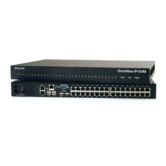
InTROdUCTIOn Digital sections table of contents Unit display diagrams Figure 1 illustrates the front panel of the OmniView IP 5232K Switch. Digital Figure 2 OmniView IP 5232K Switch – rear view Connector table Figure 1 OmniView IP 5232K Switch – front view Connector function led and button table... -
Page 10: Installation
InsTallaTIOn sections table of contents Pre-Installation Guidelines Mechanical loading Mount the equipment in the rack in such a way that a hazardous condition is not achieved due to uneven mechanical loading. • Place cables away from fluorescent lights, air conditioners, and machines that are likely to generate electrical noise. Circuit overloading When connecting the equipment to the supply circuit, consider the •... - Page 11 InsTallaTIOn sections table of contents Rack-mounting the sMb IP KVM switch Place the brackets toward the front of the unit so that the unit can be mounted front facing; or place the brackets toward the rear of the unit so that it can be mounted rear facing on the back of a rack. Figure 4 Rack-mount the Switch using the supplied rack-mount kit.
-
Page 12: Connecting The System
InsTallaTIOn sections table of contents Connecting the system OmniView IP 5216K/5232K Switch PS/2, USB, and Sun Servers Server Interface Modules TCP/IP Local User Remote User 1 Remote User 2 Figure 5 Switch’s system overview OmniViewIP 5216K/5232K... -
Page 13: The Server Interface Modules (Sims)
InsTallaTIOn sections table of contents The server Interface Modules (sIMs) Each computer/server is directly connected to the Switch via the appropriate SIM using CAT5 cables in a star configuration. No external power is needed at the remote SIMs. The SIMs draw their power from the computer’s keyboard port (PS/2 SIM) or from the USB port (USB SIM). The figures below illustrate the SIM PS/2 and USB. Figure 6 USB SIM2 (part no. -
Page 14: Connecting A Ps/2 Sim
InsTallaTIOn sections table of contents Connecting a Ps/2 sIM Connecting a Usb sIM Figure 8 illustrates the PS/2 SIM connections. The USB SIM supports Windows 2000 and later, Sun, SGI, and all modern Linux distributions. The connections for USB SIM are exactly Power down the server the same. Figure 9 illustrates the USB SIM and its connections. Connect the mouse connector to the computer’s mouse port. -
Page 15: Connecting To The Network
InsTallaTIOn sections table of contents Connecting to the network Connecting the power supply Connect the network cable to the LAN port of the Switch. This must be Using the power cord provided, connect the Switch to a socket done before powering on the Switch. outlet with a grounding connection. -
Page 16: Setting The Ip Address
InsTallaTIOn sections table of contents setting the IP address Press “F2”. The Settings window appears (see Figure 11). By default, the Switch boots with an automatically assigned IP address from a DHCP (Dynamic Host Configuration Protocol) server on the network. The DHCP server provides a valid IP address, gateway address, and subnet mask. -
Page 17: Changing The Network Parameters
InsTallaTIOn sections table of contents Changing the network parameters Enable DHCP – When a DHCP server is active on the same network to which the Switch is connected, DHCP provides automatic IP assignment. When DHCP is disabled (Recommended) – You can assign a fixed IP address to the Switch. Consult your network administrator regarding the use of the DHCP. When DHCP is disabled, enter the IP address, subnet Mask, and Gateway as given by your network administrator. -
Page 18: Web Interface
Windows Vista note! To log in to the web configuration interface with when Belkin’s root certificate is installed. Windows Vista, run Internet Explorer as “administrator.” To do this, On first connection, install the Belkin certificate and ActiveX control. You right-click the Internet Explorer icon on the task bar and select “Run” as must be logged in as an administrator on your computer to install the “administrator.”... -
Page 19: Logging In
Web InTeRfaCe sections table of contents logging in To complete the initial setup via the web configuration interface: Open your web browser (Internet Explorer version 6.0 or higher). Type the Switch’s system IP address—http or https://IP address/ - and press “Enter”. The login page appears (see Figure 13). Figure 14 Targets page By default, an administrator can access all connected Targets, so they all appear on the Targets page. -
Page 20: Connecting To A Target Server
Web InTeRfaCe sections table of contents Connecting to a target server network > Configuration To connect to a target, click the desired target in the Server Name Consult your network administrator for the network settings if necessary. column. The screen of the target appears inside the remote console window. The “Accessing a Target Server” section on page 28 explains device name –... -
Page 21: Omniview Ip Central Access Appliance 5000Hq
Web InTeRfaCe sections table of contents OmniView IP Central access appliance 5000HQ Under LAN in Figure 14, is the following: OmniView IP 5000HQ is a centralized, IP-based system for secure enable dHCP – When a DHCP server is active on the same network control of servers and network devices, power, and user administration to which the Switch is connected, DHCP provides automatic IP in the datacenter environment. -
Page 22: Administration > User Settings
Web InTeRfaCe sections table of contents administration > User settings administrator An administrator has unrestricted access to all windows and settings and can “take over” any active session. An administrator can change the From the menu, click “User Settings” and Figure 16 appears. name and password and target server permissions of all users. -
Page 23: Adding A User
Web InTeRfaCe sections table of contents adding a user editing a user To add a user: To edit a user: Click and type a name and a password. The password Select the user from the user drop-down menu. must be at least six characters (letters or numbers), and must not You can now change all the parameters—user name, permission, include the user name, even if other characters are added. -
Page 24: Administration > Server Name Edit
Web InTeRfaCe sections table of contents administration > server name edit In the “Server Name” section, change the name of the connected servers by selecting the server name and typing a new name. Click Give the servers connected to the Switch unique names, so that users to save changes. -
Page 25: Administration > Server Access List
Web InTeRfaCe sections table of contents administration > server access list Select a user from the user drop-down menu. Check the target servers the user can access (according to his or By default, access is allowed to all servers for administrators. For other her access permissions). -
Page 26: Security > Settings
Web InTeRfaCe sections table of contents security > settings Password Policy For local and remote users, you have the option of a standard or high security level of password. The table below shows the parameters of the Configure the security features, such as Account Blocking, Password two options. -
Page 27: Security > Ssl Certificate
Maintenance > switch Upgrade You can install an SSL certificate. Upgrade the Switch firmware to take advantage of new features. Download the firmware from the support section of Belkin’s website at To do so: www.belkin.com/support. Save the firmware file on the client computer. -
Page 28: Maintenance > Sim Upgrade
Upgrade the SIM firmware to take advantage of new features. Download You can restore the Switch to the factory settings. This restores the the firmware from the support section of the Belkin website at www. original Switch parameters, resetting all the information added by belkin.com/support. -
Page 29: Set Time And Date
Web InTeRfaCe sections table of contents set Time and date back Up and Restore The time and date set feature is used when recording log events. To set You can back up all configuration data to restore it at a later date. To the time and date: do so: From the menu, select “Time &... -
Page 30: Saving Changes And Logging Out
Web InTeRfaCe sections table of contents saving Changes and logging Out To save any configuration changes, click the relevant button on the current page. This could be or just To restart the Switch, press To exit the Configuration menu and close the session, click Only one administrator can log in to the Configuration area at a time. After the idle timeout (see the “Security >... -
Page 31: Remote Access
ReMOTe aCCess sections table of contents accessing a Target server On the remote console you have the following: server name – The currently accessed server identity can be checked any time by looking at the “Server name” on the Internet Explorer Log in to the web interface, as explained on page 16. The web interface title bar. opens at the Targets page (see Figure 14 on page 16). To connect to a target or serial device, click the desired target/device in the Toolbar icon –... -
Page 32: The Toolbar
ReMOTe aCCess sections table of contents The Toolbar Changing the performance settings To maximize the toolbar: You can alter the bandwidth settings from the toolbar. Click the arrow . Click again to minimize the toolbar. To alter the settings: When maximized, the toolbar can be dragged and dropped to anywhere From the toolbar, click . The “Settings...” dialog box appears (see on the screen, by dragging the icon . -
Page 33: Adjusting The Video Settings
ReMOTe aCCess sections table of contents bandwidth adjusting the video settings Choose from the following options: To change the video settings: adaptive – Automatically adapts to the best compression and colors From the toolbar, click . You have the following options: according to the network conditions. -
Page 34: Manual Video Adjust
ReMOTe aCCess sections table of contents Manual video adjust Use the manual video adjustment for fine-tuning the target server video settings after auto adjustment. This feature should also be used for adapting to a noisy environment, a non-standard VGA signal, or when in full-screen DOS/CLI mode. -
Page 35: Auto Video Adjust
ReMOTe aCCess sections table of contents auto video adjust To adjust the video automatically: Click “Auto Video Adjust”. The process takes a few seconds. If the process runs for more than three times, there is an abnormal noise level. Check the video cable and verify that no dynamic video application is running on the target server’s desktop. - Page 36 ReMOTe aCCess sections table of contents To record a key sequence: To edit a key sequence: From the Special Key Manager box, press “Record New”. The Add From the Special Key Manager Dialog box, select the desired key. Special Key dialog box appears (see Figure 31). Click “Edit”. Click “Start Recording”. Press the desired keys. The keys appear in the area provided. Click “Stop Recording”. Click “OK”. Figure 31 Add Special Key Dialog box Give the key sequence a name in the Label field.
-
Page 37: Synchronizing Mouse Pointers
ReMOTe aCCess sections table of contents synchronizing mouse pointers Server-mouse settings for common operating systems: When working at the client computer, two mouse pointers appear: the Windows 2000, XP, 2003 server, Vista client computer’s is on top of the target server’s. The mouse pointers should be synchronized. The following explains what to do if they are Go to the Windows “Control Panel”. - Page 38 ReMOTe aCCess sections table of contents Red Hat , fedora, and other linux distributions ® When accessing the target server, the mice may appear at a distance to each other. Go to “Mouse Preferences”. To align the mouse pointers: Then navigate to the “Motion” tab. From the toolbar, click “ / Align” or press (left) “Ctrl+M”...
-
Page 39: Manual Settings
ReMOTe aCCess sections table of contents Manual settings Select the target server’s operating system and click “OK”. Instructions and sliders appear. Note: You must do this If the mouse settings on the target server were ever changed, or when configuration on every port. the operating system on the target server is Windows XP, 2003 Server, Follow the instructions and set any relevant sliders to the same Vista, or 2008 Server, or Linux, Novell, SCO UNIX... - Page 40 ReMOTe aCCess sections table of contents advanced – Mouse emulation Click and the “Mouse Emulation” dialog box appears (see Figure 33). Figure 34 Mouse Emulation dialog box for use with touch pads Press “OK” to save settings. note: This “Mouse Emulation” setting is used to determine the correct reset sequence for a local mouse. Setting it incorrectly may lead to a jumpy or non-operational local console mouse after a remote user disconnects it Figure 33 Mouse Emulation dialog box from the Switch.
-
Page 41: Calibrating Mice Pointers
ReMOTe aCCess sections table of contents Calibrating mice pointers adjustments in general A target server may have a different mouse pointer speed to the client The above adjustments, namely: computer. Calibrating automatically discovers the mouse speed of the target server and aligns the two pointers. •... -
Page 42: Globe Icon Menu Features
ReMOTe aCCess sections table of contents Globe icon menu features Hide Toolbar – Check this option to hide the toolbar from the next reconnection onward. To toggle the toolbar on and off, press “F9” or double-click the system tray icon Right-click the globe icon and a menu appears. From this menu you can access the connected devices. -
Page 43: Virtual Media
ReMOTe aCCess sections table of contents Virtual media Mounting a drive Click “Virtual Media” and the “Virtual Media” dialog box appears With virtual media, you can virtually mount removable mass storage (see Figure 36). All connected mass storage devices appear in the devices connected to the client computer onto the target server. “Local Drives”... - Page 44 ReMOTe aCCess sections table of contents Mounting an IsO file • Only drives identified by the client’s operating system as drives with removable storage can be mounted as virtual media. Many An ISO image (.iso) is a disk image of an ISO 9660 file system, and USB-attached hard disks identify themselves to the operating refers to any optical disc image, even a UDF image.
-
Page 45: Full-Screen Mode
ReMOTe aCCess sections table of contents full-screen mode disconnecting the remote session Work on the target server as if you are working on a local computer with To disconnect the session, click on the toolbar. The Login page full-screen mode. appears. -
Page 46: Changing The Password
ReMOTe aCCess sections table of contents Changing the password To change the password, click “Password” from the menu and the following appears. Figure 37 Events log Navigate through the event pages using the forward or backward arrows, marked as (A) in Figure 37. Figure 36 Password From the drop-down menu, marked as (B) in Figure 37, choose the number of events that will appear on each page (10–40). -
Page 47: Local Access
lOCal aCCess sections table of contents navigating the Osd Main window This section explains how to operate the Switch locally via the OSD. The Osd To navigate up and down, use the up and down arrow keys. To exit the OSD, press “Esc”. To display the OSD: selecting a computer From the local keyboard, press the left “Scroll Lock” key twice. The OSD Main window appears (see Figure 38). -
Page 48: Moving The Confirmation Label – F1
lOCal aCCess sections table of contents Moving the Confirmation label – f1 The confirmation OSD label that appears briefly showing which computer is currently accessed can be positioned anywhere on the screen. To position the label from the Main window: Figure 39 Image Tuning label Navigate to a computer line using the up and down arrow keys. -
Page 49: The Settings Window – F2
lOCal aCCess sections table of contents The settings window – f2 5000HQ MnG – Press the space bar to toggle between enabling and disabling management by the 5000HQ. When enabled, the Switch is remotely managed by OmniView IP Central Management Press “F2”. -
Page 50: Saving Changes To The Settings
lOCal aCCess sections table of contents ddC – f10 saving changes to the settings Display Data Channel (DDC) is a VESA standard for communication To save changes to the settings and return to the Main window, between a monitor and a video adapter. press “Esc”. -
Page 51: Additional Information
addITIOnal InfORMaTIOn sections table of contents Technical specifications Target server Dimensions (H x D x W) 44 x 270 x 431mm/1.7 x 10.6 x 17 in. Windows, Novell, Linux, Sun Solaris Operating Systems Client Computer Power Input 100–240VAC, 0.8A, 50/60Hz Windows 2000 or higher with IE 6.0 or higher and ActiveX Operating Temperature 0° C to 40° C/32° F to 104° F Target server Up to 1600x1200@85Hz Storage Temperature... -
Page 52: Video Resolution And Refresh Rates
addITIOnal InfORMaTIOn sections table of contents Video Resolution and Refresh Rates 640x480 720x400 800x600 1024x768 1152x864 1152x900 1280x720 1280x768 1280x960 1280x1024 1600x1200 OmniViewIP 5216K/5232K... -
Page 53: Safety
Please include the following information: Manual name, part number, and P number. Product Registration You may register your product online by going to https://www.belkin.com/registration/. This will assist Belkin in contacting you regarding important information regarding the use of your product. OmniViewIP 5216K/5232K... -
Page 54: Information
Of COnfORMITY WITH fCC RUles fOR eleCTROMaGneTIC COMPaTIbIlITY Ce declaration of Conformity We, Belkin International, Inc., of 501 West Walnut Street, Compton, CA 90220, declare under our sole responsibility that the products: We, Belkin International, Inc., declare under our sole responsibility that... - Page 55 Where you purchased the product. limited warranty to repair or replace any such discontinued products. c. When you purchased the product. In the event that Belkin is unable to repair or replace the product (for example, because it has been discontinued), Belkin will offer either a d. Copy of original receipt.
- Page 56 Belkin reserves the right to review the damaged Belkin product. All Some states do not allow limitations on how long an implied warranty costs of shipping the Belkin product to Belkin for inspection shall be lasts, so the above limitations may not apply to you.
- Page 57 Tuggerah Business Park +44 (0) 1933 35 2000 Tuggerah, NSW 2259, Australia +44 (0) 1933 31 2000 fax +61 (0) 2 4350 4600 +61 (0) 2 4350 4700 fax © 2009 Belkin International, Inc. All rights reserved. All trade names are registered trademarks of respective manufacturers listed. Windows, Windows Vista, Microsoft, NT, Internet Explorer, and ActiveX are either registered trademarks or trademarks of Microsoft Corporation in the United States and/or other countries.
Need help?
Do you have a question about the OmniView 5216K and is the answer not in the manual?
Questions and answers