Table of Contents

Related Manuals for Gigabyte GA-H61M-D2P-B3


Summary of Contents for Gigabyte GA-H61M-D2P-B3
- Page 1 GA-H61M-D2P-B3 LGA1155 socket motherboard for Intel Core i7 processor family/ ® ™ Intel Core i5 processor family/Intel Core i3 processor family/ ® ™ ® ™ Intel Pentium processors/Intel Celeron processors ® ® ® ® User's Manual Rev. 1002 12ME-H61M2PB-1002R...
-
Page 3: Identifying Motherboard Revision
The trademarks mentioned in this manual are legally registered to their respective owners. Disclaimer Information in this manual is protected by copyright laws and is the property of GIGABYTE. Changes to the specifications and features in this manual may be made by GIGABYTE without prior notice. -
Page 4: Table Of Contents
Table of Contents GA-H61M-D2P-B3 Motherboard Layout ................5 Chapter 1 Hardware Installation ..................6 Installation Precautions ..................6 Product Specifications ..................7 Installing the CPU and CPU Cooler ..............9 Installing the Memory ..................10 Installing an Expansion Card ................. 10 Back Panel Connectors .................. 11 Internal Connectors .................. -
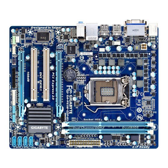
Page 5: Ga-H61M-D2P-B3 Motherboard Layout
GA-H61M-D2P-B3 Motherboard Layout ATX_12V KB_MS VGA_DVI LGA1155 CPU_FAN R_USB1 R_USB2 USB_LAN Realtek RTL8111E AUDIO PCIe to GA-H61M-D2P-B3 Bridge DDR3_1 DDR3_2 CODEC PCIEX16 B_BIOS M_BIOS PCI1 CLR_CMOS Intel ® PCI2 IT8728 PCIEX4 SATA2_0 SATA2_1 SYS_FAN SATA2_2 SATA2_3 F_AUDIO COMA F_PANEL F_USB2 F_USB1 Box Contents GA-H61M-D2P-B3 motherboard... -
Page 6: Chapter 1 Hardware Installation
Chapter 1 Hardware Installation Installation Precautions The motherboard contains numerous delicate electronic circuits and components which can become damaged as a result of electrostatic discharge (ESD). Prior to installation, carefully read the user's manual and follow these procedures: Prior to installation, do not remove or break motherboard S/N (Serial Number) sticker or •... -
Page 7: Product Specifications
Dual channel memory architecture Š Support for DDR3 1333/1066/800 MHz memory modules Š Support for non-ECC memory modules Š (Go to GIGABYTE's website for the latest supported memory speeds and memory modules.) Onboard Integrated in the Chipset: Š Graphics - 1 x D-Sub port - 1 x DVI-D port, supporting a maximum resolution of 1920x1200 * The DVI-D port does not support D-Sub connection by adapter. - Page 8 Windows 7/Vista/XP Š ® System Form Factor Micro ATX Form Factor; 24.4cm x 20.0cm Š * GIGABYTE reserves the right to make any changes to the product specifications and product-related in formation without prior notice. Hardware Installation - 8 -...
-
Page 9: Installing The Cpu And Cpu Cooler
Read the following guidelines before you begin to install the CPU: Make sure that the motherboard supports the CPU. • (Go to GIGABYTE's website for the latest CPU support list.) Always turn off the computer and unplug the power cord from the power outlet before installing •... -
Page 10: Installing The Memory
Make sure that the motherboard supports the memory. It is recommended that memory of the • same capacity, brand, speed, and chips be used. (Go to GIGABYTE's website for the latest supported memory speeds and memory modules.) Always turn off the computer and unplug the power cord from the power outlet before installing •... -
Page 11: Back Panel Connectors
Back Panel Connectors PS/2 Keyboard and PS/2 Mouse Port Use the upper port (green) to connect a PS/2 mouse and the lower port (purple) to connect a PS/2 key- board. D-Sub Port The D-Sub port supports a 15-pin D-Sub connector. Connect a monitor that supports D-Sub connection to this port. -
Page 12: Internal Connectors
Internal Connectors ATX_12V F_AUDIO F_USB1/F_USB2 CPU_FAN SYS_FAN COMA SATA2_0/1/2/3 CLR_CMOS F_PANEL Read the following guidelines before connecting external devices: First make sure your devices are compliant with the connectors you wish to connect. • Before installing the devices, be sure to turn off the devices and your computer. Unplug the •... - Page 13 1/2) ATX_12V/ATX (2x2 12V Power Connector and 2x12 Main Power Connector) With the use of the power connector, the power supply can supply enough stable power to all the components on the motherboard. Before connecting the power connector, first make sure the power supply is turned off and all devices are properly installed.
-
Page 14: Fan Headers
3/4) CPU_FAN/SYS_FAN (Fan Headers) The motherboard has a 4-pin CPU fan header (CPU_FAN) and a 4-pin system fan header (SYS_FAN). Most fan headers possess a foolproof insertion design. When connecting a fan cable, be sure to connect it in the correct orientation (the black connector wire is the ground wire). The motherboard supports CPU fan speed control, which requires the use of a CPU fan with fan speed control design. -
Page 15: Front Panel Header
6) F_PANEL (Front Panel Header) Connect the power switch, reset switch, speaker, chassis intrusion switch/sensor and system status indicator on the chassis to this header according to the pin assignments below. Note the positive and negative pins before connecting the cables. Message/Power/ Power Speaker... -
Page 16: Front Panel Audio Header
7) F_AUDIO (Front Panel Audio Header) The front panel audio header supports Intel High Definition audio (HD) and AC'97 audio. You may con- nect your chassis front panel audio module to this header. Make sure the wire assignments of the mod- ule connector match the pin assignments of the motherboard header. - Page 17 9) LPT (Parallel Port Header) The LPT header can provide one parallel port via an optional LPT port cable. For purchasing the optional LPT port cable, please contact the local dealer. Pin No. Definition Pin No. Definition STB- AFD- ERR- INIT- ACK- SLIN-...
-
Page 18: Clearing Cmos Jumper
11) CLR_CMOS (Clearing CMOS Jumper) Use this jumper to clear the CMOS values (e.g. date information and BIOS configurations) and reset the CMOS values to factory defaults. To clear the CMOS values, place a jumper cap on the two pins to tem- porarily short the two pins or use a metal object like a screwdriver to touch the two pins for a few seconds. -
Page 19: Chapter 2 Bios Setup
To see more advanced BIOS Setup menu options, you can press <Ctrl> + <F1> in the main menu of the BIOS Setup program. To upgrade the BIOS, use either the GIGABYTE Q-Flash or @BIOS utility. Q-Flash allows the user to quickly and easily upgrade or back up BIOS without entering the operating •... -
Page 20: Mb Intelligent Tweaker(M.i.t.)
If you do not find the settings you want in the Main Menu or a submenu, press <Ctrl>+<F1> to • access more advanced options. Load Optimized Defaults item to set your When the system is not stable as usual, select the •... - Page 21 CMOS Setup Utility-Copyright (C) 1984-2010 Award Software MB Intelligent Tweaker(M.I.T.) Item Help M.I.T Current Status [Press Enter] Menu Level Advanced Frequency Settings [Press Enter] Advanced Memory Settings [Press Enter] Advanced Voltage Settings [Press Enter] Miscellaneous Settings [Press Enter] BIOS Version BCLK...
- Page 22 Advanced CPU Core Features CMOS Setup Utility-Copyright (C) 1984-2010 Award Software Advanced CPU Core Features Item Help CPU Clock Ratio [30X] Menu Level CPU Frequency 3.00GHz (100x30) Intel(R) Turbo Boost Tech. [Auto] (Note) -Turbo Ratio(1-Core) [Auto] (Note) -Turbo Ratio(2-Core) [Auto] (Note) -Turbo Ratio(3-Core)
- Page 23 CPU Multi-Threading (Note) Allows you to determine whether to enable multi-threading technology when using an Intel CPU that supports this function. This feature only works for operating systems that support multi-processor mode. (Default: Enabled) CPU Enhanced Halt (C1E) (Note) Enables or disables Intel CPU Enhanced Halt (C1E) function, a CPU power-saving function in system halt state.
- Page 24 Advanced Memory Settings CMOS Setup Utility-Copyright (C) 1984-2010 Award Software Advanced Memory Settings Item Help System Memory Multiplier (SPD) [Auto] Menu Level Memory Frequency (Mhz) 1333 1333 Performance Enhance [Turbo] DRAM Timing Selectable (SPD) [Auto] Profile DDR Voltage 1.5V Profile VTT Voltage 1.05V x Channel Interleaving Auto...
- Page 25 >>>>> Channel A/B Timing Settings CMOS Setup Utility-Copyright (C) 1984-2010 Award Software Channel A Timing Settings Item Help >>>>> Channel A Standard Timing Control Menu Level x CAS Latency Time Auto x tRCD Auto x tRP Auto x tRAS Auto >>>>>...
- Page 26 Command Rate(CMD) Options are: Auto (default), 1~3. >>>>> Channel A/B Misc Timing Control IO Latency Options are: Auto (default), 1~31. Round Trip Latency Options are: Auto (default), 1~255. Advanced Voltage Settings CMOS Setup Utility-Copyright (C) 1984-2010 Award Software Advanced Voltage Settings Item Help ****** Mother Board Voltage Control ****** Menu Level ...
-
Page 27: Miscellaneous Settings
Miscellaneous Settings CMOS Setup Utility-Copyright (C) 1984-2010 Award Software Miscellaneous Settings Item Help Isochronous Support [Enabled] Menu Level Virtualization Technology (Note) [Enabled] : Move Enter: Select +/-/PU/PD: Value F10: Save ESC: Exit F1: General Help F5: Previous Values F6: Fail-Safe Defaults F7: Optimized Defaults Isochronous Support... -
Page 28: Standard Cmos Features
Standard CMOS Features CMOS Setup Utility-Copyright (C) 1984-2010 Award Software Standard CMOS Features Item Help Date (mm:dd:yy) Fri, Dec 17 2010 Menu Level Time (hh:mm:ss) 22:31:24 IDE Channel 0 Master [None] IDE Channel 1 Master [None] IDE Channel 2 Master [None] ... -
Page 29: Advanced Bios Features
Halt On Allows you to determine whether the system will stop for an error during the POST. Options are: "All Errors," "No Errors," "All, But Keyboard". (Default) Memory These fields are read-only and are determined by the BIOS POST. Advanced BIOS Features CMOS Setup Utility-Copyright (C) 1984-2010 Award Software Advanced BIOS Features Item Help... - Page 30 Password Check Specifies whether a password is required every time the system boots, or only when you enter BIOS Setup. After configuring this item, set the password(s) under the Set Supervisor/User Password item in the BIOS Main Menu. Setup A password is only required for entering the BIOS Setup program. (Default) System A password is required for booting the system and for entering the BIOS Setup pro- gram.
-
Page 31: Integrated Peripherals
Integrated Peripherals CMOS Setup Utility-Copyright (C) 1984-2010 Award Software Integrated Peripherals Item Help SATA Port0-1 Native Mode [Enabled] Menu Level USB Controllers [Enabled] USB Legacy Function [Enabled] USB Storage Function [Enabled] Azalia Codec [Auto] Onboard H/W LAN [Enabled] SMART LAN [Press Enter] Onboard LAN Boot ROM [Disabled]... -
Page 32: Power Management Setup
Onboard LAN Boot ROM Allows you to decide whether to activate the boot ROM integrated with the onboard LAN chip. (Default: Disabled) Onboard Serial Port 1 Enables or disables the first serial port and specifies its base I/O address and corresponding interrupt. Options are: Auto, 3F8/IRQ4 (default), 2F8/IRQ3, 3E8/IRQ4, 2E8/IRQ3, Disabled. - Page 33 PME Event Wake Up Allows the system to be awakened from an ACPI sleep state by a wake-up signal from a PCI or PCIe de- vice. Note: To use this function, you need an ATX power supply providing at least 1A on the +5VSB lead. (Default: Enabled) Power On by Ring Allows the system to be awakened from an ACPI sleep state by a wake-up signal from a modem that...
-
Page 34: Pc Health Status
PC Health Status CMOS Setup Utility-Copyright (C) 1984-2010 Award Software PC Health Status Item Help Reset Case Open Status [Disabled] Menu Level Case Opened Vcore 1.172V DDR15V 1.516V +12V 11.779V 1.076V Current System Temperature Current CPU Temperature Current CPU FAN Speed 3375 RPM Current SYSTEM FAN Speed 0 RPM... -
Page 35: Load Fail-Safe Defaults
Slope PWM Allows you to control the CPU fan speed. This item is configurable only when CPU Smart FAN Control is set to Manual. Options are: 0.75 PWM value / C ~ 2.50 PWM value / CPU Smart FAN Mode Specifies how to control CPU fan speed. -
Page 36: Set Supervisor/User Password
2-11 Set Supervisor/User Password CMOS Setup Utility-Copyright (C) 1984-2010 Award Software MB Intelligent Tweaker(M.I.T.) Load Fail-Safe Defaults Standard CMOS Features Load Optimized Defaults Advanced BIOS Features Set Supervisor Password Integrated Peripherals Set User Password Power Management Setup Save &... -
Page 37: Exit Without Saving
2-13 Exit Without Saving CMOS Setup Utility-Copyright (C) 1984-2010 Award Software MB Intelligent Tweaker(M.I.T.) Load Fail-Safe Defaults Standard CMOS Features Load Optimized Defaults Quit Without Saving (Y/N)? N Advanced BIOS Features Set Supervisor Password Integrated Peripherals Set User Password ... - Page 38 Appendix - 38 -...
- Page 39 - 39 - Appendix...
- Page 40 WEB address (English): http://www.gigabyte.com WEB address (Chinese): http://www.gigabyte.tw You may go to the GIGABYTE website, select your language in the language list on the top right corner of the website. • GIGABYTE Global Service System To submit a technical or non-technical (Sales/Market- ing) question, please link to: http://ggts.gigabyte.com.tw...
Need help?
Do you have a question about the GA-H61M-D2P-B3 and is the answer not in the manual?
Questions and answers