Table of Contents
Advertisement
Advertisement
Table of Contents

Related Manuals for Gigabyte GA-H61M-S2P-B3


Summary of Contents for Gigabyte GA-H61M-S2P-B3
- Page 1 GA-H61M-S2P-B3 User's Manual Rev. 1001 12ME-61MS2PB-1001R...
-
Page 3: Identifying Motherboard Revision
The trademarks mentioned in this manual are legally registered to their respective owners. Disclaimer Information in this manual is protected by copyright laws and is the property of GIGABYTE. Changes to the specifications and features in this manual may be made by GIGABYTE with- out prior notice. -
Page 4: Table Of Contents
Table of Contents GA-H61M-S2P-B3 Motherboard Layout .................5 GA-H61M-S2P-B3 Motherboard Block Diagram ............6 Chapter 1 Hardware Installation ..................7 Installation Precautions ................... 7 Product Specifications ..................8 Installing the CPU and CPU Cooler............... 10 Installing the Memory ..................11 Installing an Expansion Card ................11 Back Panel Connectors ................. -
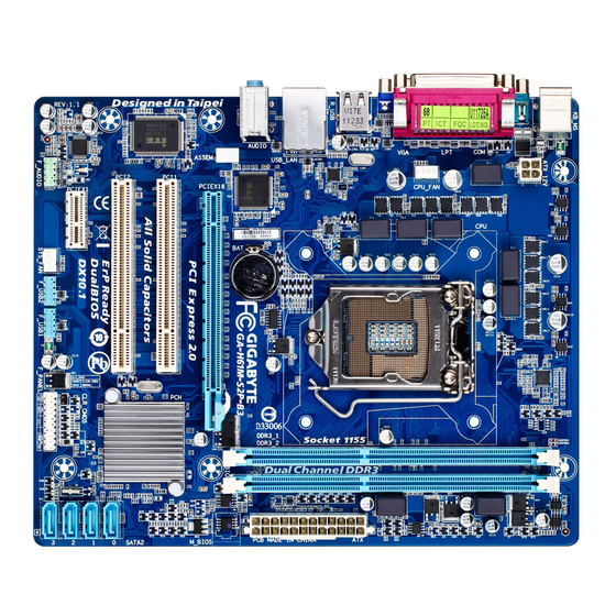
Page 5: Ga-H61M-S2P-B3 Motherboard Layout
GA-H61M-S2P-B3 Motherboard Layout KB_MS ATX_12V LGA1155 CPU_FAN R_USB Atheros AR8151 USB_LAN PCIe to PCI GA-H61M-S2P-B3 AUDIO Bridge PCIEX16 PCI1 Intel ® PCI2 SATA2_0 CODEC PCIEX1 SATA2_1 CLR_CMOS SATA2_2 F_USB2 F_USB1 F_AUDIO SATA2_3 SYS_FAN F_PANEL Box Contents GA-H61M-S2P-B3 motherboard Motherboard driver disk Two SATA cables User's Manual I/O Shield... -
Page 6: Ga-H61M-S2P-B3 Motherboard Block Diagram
GA-H61M-S2P-B3 Motherboard Block Diagram 1 PCI Express x16 CPU CLK+/- (100 MHz) LGA1155 DDR3 1333/1066/800 MHz Dual Channel Memory PCIe CLK (100 MHz) PCI Express Bus Dual BIOS D-Sub PCI Express Bus 4 SATA 3Gb/s Intel ® PCIe CLK 8 USB 2.0/1.1 (100 MHz) Atheros PCIe to PCI... -
Page 7: Chapter 1 Hardware Installation
Chapter 1 Hardware Installation Installation Precautions The motherboard contains numerous delicate electronic circuits and components which can become damaged as a result of electrostatic discharge (ESD). Prior to installation, carefully read the user's manual and follow these procedures: Prior to installation, do not remove or break motherboard S/N (Serial Number) sticker or •... -
Page 8: Product Specifications
Dual channel memory architecture Š Support for DDR3 1333/1066/800 MHz memory modules Š Support for non-ECC memory modules Š (Go to GIGABYTE's website for the latest supported memory speeds and memory modules.) Onboard Chipset: Š Graphics 1 x D-Sub port... - Page 9 Support for Microsoft Windows 7/Vista/XP Š ® System Form Factor Micro ATX Form Factor; 24.4cm x 20cm Š * GIGABYTE reserves the right to make any changes to the product specifications and product-related information without prior notice. - 9 - Hardware Installation...
-
Page 10: Installing The Cpu And Cpu Cooler
Read the following guidelines before you begin to install the CPU: Make sure that the motherboard supports the CPU. • (Go to GIGABYTE's website for the latest CPU support list.) Always turn off the computer and unplug the power cord from the power outlet before installing •... -
Page 11: Installing The Memory
Make sure that the motherboard supports the memory. It is recommended that memory of the • same capacity, brand, speed, and chips be used. (Go to GIGABYTE's website for the latest supported memory speeds and memory modules.) Always turn off the computer and unplug the power cord from the power outlet before installing •... -
Page 12: Back Panel Connectors
Back Panel Connectors PS/2 Keyboard and PS/2 Mouse Port Use the upper port (green) to connect a PS/2 mouse and the lower port (purple) to connect a PS/2 keyboard. Parallel Port Use the parallel port to connect devices such as a printer, scanner and etc. The parallel port is also called a printer port. -
Page 13: Internal Connectors
Internal Connectors ATX_12V F_PANEL F_AUDIO CPU_FAN F_USB1/F_USB2 SYS_FAN CLR_CMOS SATA2_0/1/2/3 Read the following guidelines before connecting external devices: First make sure your devices are compliant with the connectors you wish to connect. • Before installing the devices, be sure to turn off the devices and your computer. Unplug the •... - Page 14 1/2) ATX_12V/ATX (2x2 12V Power Connector and 2x12 Main Power Connector) With the use of the power connector, the power supply can supply enough stable power to all the com- ponents on the motherboard. Before connecting the power connector, first make sure the power supply is turned off and all devices are properly installed.
-
Page 15: Fan Headers
3/4) CPU_FAN/SYS_FAN (Fan Headers) The motherboard has a 4-pin CPU fan header (CPU_FAN), a 4-pin system fan header (SYS_FAN). Most fan headers possess a foolproof insertion design. When connecting a fan cable, be sure to connect it in the correct orientation (the black connector wire is the ground wire). The motherboard supports CPU fan speed control, which requires the use of a CPU fan with fan speed control design. -
Page 16: Front Panel Header
6) F_PANEL (Front Panel Header) Connect the power switch, reset switch, speaker, chassis intrusion switch/sensor and system status indicator on the chassis to this header according to the pin assignments below. Note the positive and negative pins before connecting the cables. Message/Power/ Power Sleep LED... -
Page 17: Usb 2.0/1.1 Headers
7) F_AUDIO (Front Panel Audio Header) The front panel audio header supports Intel High Definition audio (HD) and AC'97 audio. You may connect your chassis front panel audio module to this header. Make sure the wire assignments of the module con- nector match the pin assignments of the motherboard header. -
Page 18: Clearing Cmos Jumper
9) CLR_CMOS (Clearing CMOS Jumper) Use this jumper to clear the CMOS values (e.g. date information and BIOS configurations) and reset the CMOS values to factory defaults. To clear the CMOS values, place a jumper cap on the two pins to temporarily short the two pins or use a metal object like a screwdriver to touch the two pins for a few seconds. -
Page 19: Chapter 2 Bios Setup
To see more advanced BIOS Setup menu options, you can press <Ctrl> + <F1> in the main menu of the BIOS Setup program. To upgrade the BIOS, use either the GIGABYTE Q-Flash or @BIOS utility. Q-Flash allows the user to quickly and easily upgrade or back up BIOS without entering the operating •... -
Page 20: The Main Menu
The Main Menu Once you enter the BIOS Setup program, the Main Menu (as shown below) appears on the screen. Use ar- row keys to move among the items and press <Enter> to accept or enter a sub-menu. (Sample BIOS Version: E2) CMOS Setup Utility-Copyright (C) 1984-2011 Award Software MB Intelligent Tweaker(M.I.T.) Load Fail-Safe Defaults... -
Page 21: Mb Intelligent Tweaker(M.i.t.)
MB Intelligent Tweaker(M.I.T.) CMOS Setup Utility-Copyright (C) 1984-2011 Award Software MB Intelligent Tweaker(M.I.T.) Item Help M.I.T Current Status [Press Enter] Menu Level Advanced Frequency Settings [Press Enter] Advanced Memory Settings [Press Enter] Advanced Voltage Settings [Press Enter] ... -
Page 22: Cpu Clock Ratio
M.I.T. Current Status This screen provides information on CPU/memory frequencies/parameters. Advanced Frequency Settings CMOS Setup Utility-Copyright (C) 1984-2011 Award Software Advanced Frequency Settings Item Help CPU Clock Ratio [31X] Menu Level CPU Frequency 3.10GHz (100x31) Advanced CPU Core Features [Press Enter] >>>>>... - Page 23 Intel(R) Turbo Boost Tech. (Note) Allows you to determine whether to enable the Intel CPU Turbo Boost technology. Auto lets the BIOS automatically configure this setting. (Default: Auto) Turbo Ratio (1-Core)/(2-Core)/(3-Core)/(4-Core) (Note) Allows you to set the CPU Turbo ratios for different number of active cores. Auto sets the CPU Turbo ratios according to the CPU specifications.
- Page 24 Bi-Directional PROCHOT (Note) Auto Lets the BIOS automatically configure this setting. (Default) Enabled When the CPU or chipset detects that an overheating is occurring, PROCHOT sig- nals will be emitted to lower CPU performance to decrease heat production. Disabled Only allows the CPU to detect whether an overheating is occurring to emit PRO- CHOT signals.
- Page 25 DRAM Timing Selectable (SPD) Quick and Expert allows the Channel Interleaving, Rank Interleaving, Channel A Timing Settings, and Channel B Timing Settings items to be configurable. Options are: Auto (default), Quick, Expert. Profile DDR Voltage Displays the memory voltage as 1.5V. Profile VTT Voltage The value displayed here is dependent on the CPU being used.
- Page 26 tRRD Options are: Auto (default), 1~15. tWTR Options are: Auto (default), 1~15. Options are: Auto (default), 1~16. tWTP Options are: Auto (default), 1~31. Options are: Auto (default), 1~12 tRFC Options are: Auto (default), 1~255. tRTP Options are: Auto (default), 1~15. tFAW Options are: Auto (default), 1~63.
-
Page 27: Standard Cmos Features
DRAM Voltage The default is Auto. Miscellaneous Settings CMOS Setup Utility-Copyright (C) 1984-2011 Award Software Miscellaneous Settings Item Help Isochronous Support [Enabled] Menu Level Virtualization Technology (Note) [Enabled] : Move Enter: Select +/-/PU/PD: Value F10: Save ESC: Exit F1: General Help F5: Previous Values F6: Fail-Safe Defaults F7: Optimized Defaults... -
Page 28: Advanced Bios Features
Manual Allows you to manually enter the specifications of the hard drive when the hard • drive access mode is set to CHS. Access Mode Sets the hard drive access mode. Options are: Auto (default), CHS, LBA, Large. IDE Channel 2, 3 Master Extended IDE Drive Configure your SATA devices by using one of the two methods below: Auto... - Page 29 Allows you to set a delay time for the BIOS to initialize the hard drive as the system boots up. The ad- justable range is from 0 to 15 seconds. (Default: 0) Full Screen LOGO Show Allows you to determine whether to display the GIGABYTE Logo at system startup. Disabled displays normal POST message. (Default: Enabled) Init Display First Specifies the first initiation of the monitor display from the installed PCI graphics card, PCI Express graphics card, or the onboard graphics.
-
Page 30: Integrated Peripherals
Onboard VGA Enables or disables the onboard graphics function. Enable If No Ext PEG Activates the onboard graphics only when no PCI Express graphics card is installed. (Default) Always Enable Always activates the onboard graphics, whether or not a PCI Express graphics card is installed. If you wish to set up a dual-display configuration, set this item to Always Enable. -
Page 31: Power Management Setup
Azalia Codec Enables or disables the onboard audio function. (Default: Auto) If you wish to install a 3rd party add-in audio card instead of using the onboard audio, set this item to Disabled. Onboard H/W LAN Enables or disables the onboard LAN function. (Default: Enabled) If you wish to install a 3rd party add-in network card instead of using the onboard LAN, set this item to Disabled. - Page 32 Soft-Off by PWR-BTTN Configures the way to turn off the computer in MS-DOS mode using the power button. Instant-Off Press the power button and then the system will be turned off instantly. (Default) Delay 4 Sec. Press and hold the power button for 4 seconds to turn off the system. If the power button is pressed for less than 4 seconds, the system will enter suspend mode.
-
Page 33: Pc Health Status
AC Back Function Determines the state of the system after the return of power from an AC power loss. Soft-Off The system stays off upon the return of the AC power. (Default) Full-On The system is turned on upon the return of the AC power. Memory The system returns to its last known awake state upon the return of the AC power. -
Page 34: Load Fail-Safe Defaults
CPU Warning Temperature Sets the warning threshold for CPU temperature. When CPU temperature exceeds the threshold, BIOS will emit warning sound. Options are: Disabled (default), 60 C/140 F, 70 C/158 F, 80 C/176 C/194 CPU/SYSTEM FAN Fail Warning Allows the system to emit warning sound if the CPU/system fan is not connected or fails. Check the fan condition or fan connection when this occurs. -
Page 35: Load Optimized Defaults
2-10 Load Optimized Defaults CMOS Setup Utility-Copyright (C) 1984-2011 Award Software MB Intelligent Tweaker(M.I.T.) Load Fail-Safe Defaults Standard CMOS Features Load Optimized Defaults Advanced BIOS Features Set Supervisor Password Integrated Peripherals Set User Password Power Management Setup Save &... -
Page 36: Save & Exit Setup
2-12 Save & Exit Setup CMOS Setup Utility-Copyright (C) 1984-2011 Award Software MB Intelligent Tweaker(M.I.T.) Load Fail-Safe Defaults Standard CMOS Features Load Optimized Defaults Save to CMOS and EXIT (Y/N)? Y Advanced BIOS Features Set Supervisor Password Integrated Peripherals Set User Password ... -
Page 37: Chapter 3 Drivers Installation
Chapter 3 Drivers Installation Before installing the drivers, first install the operating system. • After installing the operating system, insert the motherboard driver disk into your optical drive. • The driver Autorun screen is automatically displayed which looks like that shown in the screen shot below. - Page 38 BIOS Setup - 38 -...
- Page 39 - 39 - BIOS Setup...
- Page 40 WEB address (English): http://www.gigabyte.com WEB address (Chinese): http://www.gigabyte.tw You may go to the GIGABYTE website, select your language in the language list on the top right corner of the website. • GIGABYTE Global Service System To submit a technical or non-technical (Sales/Market- ing) question, please link to: http://ggts.gigabyte.com.tw...
Need help?
Do you have a question about the GA-H61M-S2P-B3 and is the answer not in the manual?
Questions and answers