Table of Contents
Advertisement
Advertisement
Table of Contents

Related Manuals for Gigabyte GA-H61MA-D3V


Summary of Contents for Gigabyte GA-H61MA-D3V
- Page 1 GA-H61MA-D3V User's Manual Rev. 2001 12ME-61MAD3V-2001R...
-
Page 3: Identifying Motherboard Revision
The trademarks mentioned in this manual are legally registered to their respective owners. Disclaimer Information in this manual is protected by copyright laws and is the property of GIGABYTE. Changes to the specifications and features in this manual may be made by GIGABYTE with- out prior notice. -
Page 4: Table Of Contents
Table of Contents GA-H61MA-D3V Motherboard Layout ................5 GA-H61MA-D3V Motherboard Block Diagram ...............6 Chapter 1 Hardware Installation ..................7 Installation Precautions ................... 7 Product Specifications ..................8 Installing the CPU ..................10 Installing the Memory ..................11 Installing an Expansion Card ................11 Back Panel Connectors ................. 12 Internal Connectors .................. -
Page 5: Ga-H61Ma-D3V Motherboard Layout
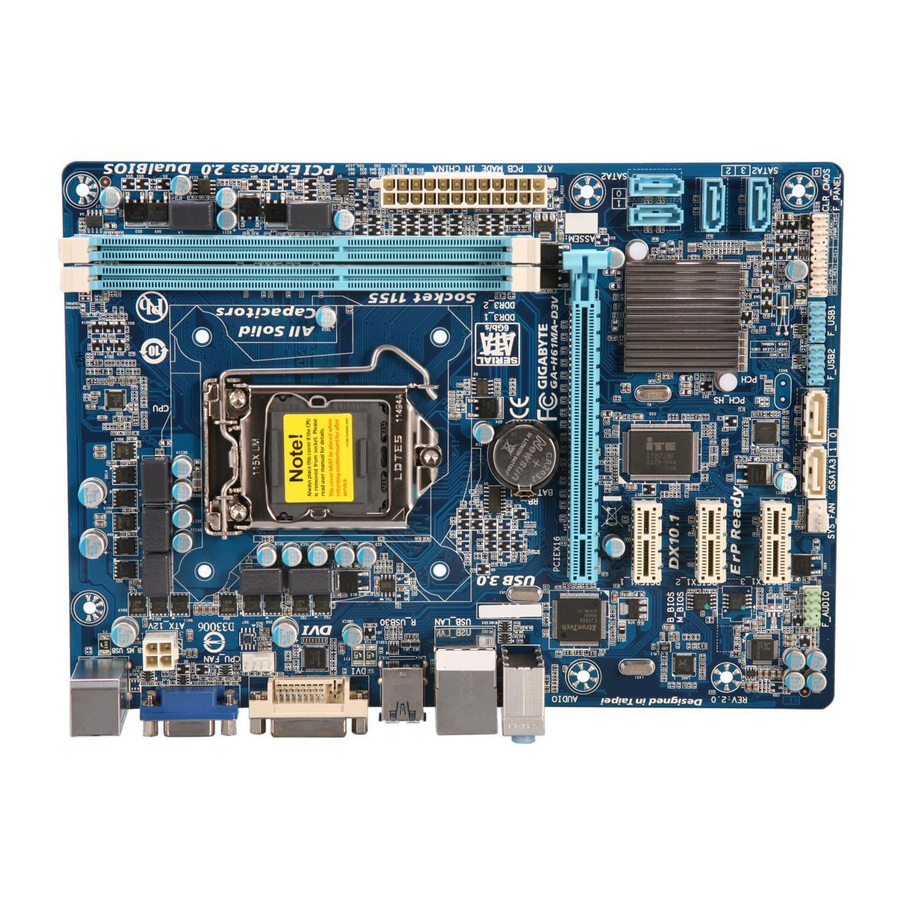
GA-H61MA-D3V Motherboard Layout KB_MS_USB ATX_12V LGA1155 CPU_FAN R_USB30 USB_LAN AUDIO GA-H61MA-D3V PCIEX16 Etron EJ168 SATA2 PCIEX1_1 Realtek/ Atheros IT8728 GbE LAN Intel ® PCIEX1_2 B_BIOS SATA2 Marvell M_BIOS 88SE9172 PCIEX1_3 CODEC CLR_CMOS GSATA3 1 0 SYS_FAN F_USB2 F_USB1 F_AUDIO F_PANEL... -
Page 6: Ga-H61Ma-D3V Motherboard Block Diagram
GA-H61MA-D3V Motherboard Block Diagram 1 PCI Express x16 CPU CLK+/- (100 MHz) LGA1155 DDR3 1333/1066/800 MHz Dual Channel Memory PCIe CLK (100 MHz) PCI Express Bus D-Sub Dual BIOS DVI-D 4 SATA 3Gb/s 2 USB 3.0/2.0 2 SATA 6Gb/s RJ45 Intel ®... -
Page 7: Chapter 1 Hardware Installation
Chapter 1 Hardware Installation Installation Precautions The motherboard contains numerous delicate electronic circuits and components which can become damaged as a result of electrostatic discharge (ESD). Prior to installation, carefully read the user's manual and follow these procedures: Prior to installation, make sure the chassis is suitable for the motherboard. •... -
Page 8: 1-2 Product Specifications
Dual channel memory architecture Š Support for DDR3 1333/1066/800 MHz memory modules Š Support for non-ECC memory modules Š (Go to GIGABYTE's website for the latest supported memory speeds and memory modules.) Onboard Integrated Graphics Processor: Š Graphics 1 x D-Sub port 1 x DVI-D port, supporting a maximum resolution of 1920x1200 * The DVI-D port does not support D-Sub connection by adapter. - Page 9 Support for Microsoft Windows 7/Vista/XP Š ® System Form Factor Micro ATX Form Factor; 24.4cm x 17.4cm Š * GIGABYTE reserves the right to make any changes to the product specifications and product-related information without prior notice. - 9 -...
-
Page 10: Installing The Cpu
Read the following guidelines before you begin to install the CPU: Make sure that the motherboard supports the CPU. • (Go to GIGABYTE's website for the latest CPU support list.) Always turn off the computer and unplug the power cord from the power outlet before installing •... -
Page 11: Installing The Memory
Make sure that the motherboard supports the memory. It is recommended that memory of the • same capacity, brand, speed, and chips be used. (Go to GIGABYTE's website for the latest supported memory speeds and memory modules.) Always turn off the computer and unplug the power cord from the power outlet before installing •... -
Page 12: Back Panel Connectors
Back Panel Connectors USB 2.0/1.1 Port The USB port supports the USB 2.0/1.1 specification. Use this port for USB devices such as a USB key- board/mouse, USB printer, USB flash drive and etc. PS/2 Keyboard/Mouse Port Use this port to connect a PS/2 mouse or keyboard. D-Sub Port The D-Sub port supports a 15-pin D-Sub connector. -
Page 13: Internal Connectors
Internal Connectors ATX_12V F_PANEL F_AUDIO CPU_FAN F_USB1/2 SYS_FAN CLR_CMOS SATA2 0/1/2/3 GSATA3 1/0 Read the following guidelines before connecting external devices: First make sure your devices are compliant with the connectors you wish to connect. • Before installing the devices, be sure to turn off the devices and your computer. Unplug the •... - Page 14 1/2) ATX_12V/ATX (2x2 12V Power Connector and 2x12 Main Power Connector) With the use of the power connector, the power supply can supply enough stable power to all the components on the motherboard. Before connecting the power connector, first make sure the power supply is turned off and all devices are properly installed.
-
Page 15: Fan Headers
3/4) CPU_FAN/SYS_FAN (Fan Headers) The motherboard has a 4-pin CPU fan header (CPU_FAN) and a 4-pin system fan header (SYS_FAN). Most fan headers possess a foolproof insertion design. When connecting a fan cable, be sure to connect it in the correct orientation (the black connector wire is the ground wire). The motherboard supports CPU fan speed control, which requires the use of a CPU fan with fan speed control design. - Page 16 DEBUG DEBUG PORT PORT 6) GSATA3 0/1 (SATA 6Gb/s Connectors, Controlled by Marvell 88SE9172 Chip) The SATA connectors conform to SATA 6Gb/s standard and are compatible with SATA 3Gb/s and SATA 1.5Gb/s standard. Each SATA connector supports a single SATA device. The Marvell 88SE9172 chip supports RAID 0 and RAID 1.
-
Page 17: Front Panel Heade
7) F_PANEL (Front Panel Header) Connect the power switch, reset switch, speaker, and system status indicator on the chassis to this header according to the pin assignments below. Note the positive and negative pins before connecting the cables. Message/Power/ Power Switch Sleep LED Speaker... -
Page 18: Usb 2.0/1.1 Headers
8) F_AUDIO (Front Panel Audio Header) The front panel audio header supports Intel High Definition audio (HD) and AC'97 audio. You may connect your chassis front panel audio module to this header. Make sure the wire assignments of the module con- nector match the pin assignments of the motherboard header. -
Page 19: Battery
10) CLR_CMOS (Clear CMOS Jumper) Use this jumper to clear the CMOS values (e.g. date information and BIOS configurations) and reset the CMOS values to factory defaults. To clear the CMOS values, use a metal object like a screwdriver to touch the two pins for a few seconds. -
Page 20: Chapter 2 Bios Setup
To access the BIOS Setup program, press the <Delete> key during the POST when the power is turned on. To upgrade the BIOS, use either the GIGABYTE Q-Flash or @BIOS utility. Q-Flash allows the user to quickly and easily upgrade or back up BIOS without entering the operating •... -
Page 21: The Main Menu
The Main Menu On the main menu of the BIOS Setup program, press arrow keys to move among the items and press <Enter> to accept or enter a sub-menu. Or you can use your mouse to select the item you want. (Sample BIOS Version: E8) Setup Menus Enter Q-Flash... -
Page 22: M.i.t
M.I.T. Whether the system will work stably with the overclock/overvoltage settings you made is dependent on your overall system configurations. Incorrectly doing overclock/overvoltage may result in damage to CPU, chipset, or memory and reduce the useful life of these components. This page is for advanced users only and we recommend you not to alter the default settings to prevent system instability or other unexpected results. - Page 23 M.I.T. Current Status This screen provides information on CPU/memory frequencies/parameters. Advanced Frequency Settings CPU Clock Ratio & Allows you to alter the clock ratio for the installed CPU. The adjustable range is dependent on the CPU being installed. CPU Frequency &...
- Page 24 CPU Clock Ratio, CPU Frequency & The settings under the two items above are synchronous to that under the same items on the Advanced Frequency Settings menu. Internal CPU PLL Overvoltage & Enabled allows CPU PLL voltage to operate at a higher value. Disabled allows CPU PLL voltage to operate at default value.
- Page 25 CPU EIST Function & (Note) Enables or disables Enhanced Intel SpeedStep Technology (EIST). Depending on CPU loading, Intel EIST technology can dynamically and effectively lower the CPU voltage and core frequency to decrease average power consumption and heat production. Auto lets the BIOS automatically configure this setting. (Default: Auto) Bi-Directional PROCHOT &...
- Page 26 DRAM Timing Selectable & Quick and Expert allows the Channel Interleaving, Rank Interleaving, and memory timing settings below to be configurable. Options are: Auto (default), Quick, Expert. Profile DDR Voltage & Displays the memory voltage as 1.50V. Profile VTT Voltage & The value displayed here is dependent on the CPU being used. Channel Interleaving &...
- Page 27 Advanced Voltage Settings CPU Vtt & Allows you to set CPU Vtt voltage. The default is Auto. DRAM Voltage & Allows you to set memory voltage. The default is Auto. PC Health Status Reset Case Open Status & Disabled Keeps or clears the record of previous chassis intrusion status. (Default) Case Opened field will show Enabled Clears the record of previous chassis intrusion status and the...
- Page 28 Case Opened & Displays the detection status of the chassis intrusion detection device attached to the motherboard CI header. If the system chassis cover is removed, this field will show "Yes", otherwise it will show "No". To clear the chassis intrusion status record, set Reset Case Open Status to Enabled, save the settings to the CMOS, and then restart your system.
-
Page 29: System
Miscellaneous Settings Isochronous Support & Determines whether to enable specific streams within the CPU and Chipset. This item is present only when you install a CPU that supports this feature. For more information about Intel CPUs' unique features, please visit Intel's website. (Default: Enabled) System This section provides information on your motherboard model and BIOS version. -
Page 30: Bios Features
System Language & Selects the default language used by the BIOS. System Date & Sets the system date. The date format is week (read-only), month, date, and year. Use <Enter> to switch between the Month, Date, and Year fields and use the up arrow or down arrow key to set the desired value. -
Page 31: Administrator Password
Enables or disables Numlock feature on the numeric keypad of the keyboard after the POST. (Default: Enabled) Full Screen LOGO Show & Allows you to determine whether to display the GIGABYTE Logo at system startup. Disabled skips the GIGABYTE Logo when the system starts up. (Default: Enabled) PCI ROM Priority &... -
Page 32: Peripherals
Peripherals LAN PXE Boot Option ROM & Allows you to decide whether to activate the boot ROM integrated with the onboard LAN chip. (Default: Disabled) SATA Controller(s) (Intel H61 Chipset) & Enables or disables the integrated SATA controllers. (Default: Enabled) SATA Mode Selection (Intel H61 Chipset) &... - Page 33 Internal Graphics Memory Size & Allows you to set the onboard graphics memory size. Options are: 32M~1024M. (Default: 64M) DVMT Total Memory Size & Allows you to allocate the DVMT memory size of the onboard graphics. Options are: 128M, 256M, MAX. (Default: 256M) Legacy USB Support &...
-
Page 34: Power Management
AHCI Mode Configures the SATA controller to AHCI mode. Advanced Host Controller Interface (AHCI) is an interface specification that allows the storage driver to enable advanced Serial ATA features such as Native Command Queuing and hot plug. RAID Mode Enables RAID for the SATA controller. Disabled Disables the SATA controller. - Page 35 Resume by Alarm & Determines whether to power on the system at a desired time. (Default: Disabled) If enabled, set the date and time as following: Wake up day: Turn on the system at a specific time on each day or on a specific day in a month. Wake up hour/minute/second: Set the time at which the system will be powered on automatically.
-
Page 36: Save & Exit
Save & Exit Save & Exit Setup & Press <Enter> on this item and select Yes. This saves the changes to the CMOS and exits the BIOS Setup program. Select No or press <Esc> to return to the BIOS Setup Main Menu. Exit Without Saving &... -
Page 37: Chapter 3 Drivers Installation
Chapter 3 Drivers Installation Before installing the drivers, first install the operating system. • After installing the operating system, insert the motherboard driver disk into your optical drive. The • driver Autorun screen is automatically displayed which looks like that shown in the screen shot below. -
Page 38: Chapter 4 Appendix
Chapter 4 Appendix 4-1 Configuring SATA Hard Drive(s) Before you begin Please prepare: At least two SATA hard drives (to ensure optimal performance, it is recommended that you use two hard • drives with identical model and capacity). If you do not want to create RAID, you may prepare only one hard drive. - Page 39 c. Quick Init: Select whether to quickly erase old data on the hard drives when creating the array. d. Cache Mode: Select write-back or write-through cache. e. VD Name: Enter an array name with 1~10 letters (letters cannot be special characters). NEXT and press <Enter>...
-
Page 40: Regulatory Statements
"end of life" product. Restriction of Hazardous Substances (RoHS) Directive Statement GIGABYTE products have not intended to add and safe from hazardous substances (Cd, Pb, Hg, Cr+6, PBDE and PBB). The parts and components have been carefully selected to meet RoHS requirement. Moreover, we at GIGABYTE are continuing our efforts to develop products that do not use internationally banned toxic chemicals. - Page 41 - 41 -...
- Page 42 - 42 -...
- Page 43 - 43 -...
- Page 44 Tech. and Non-Tech. Support (Sales/Marketing) : http://ggts.gigabyte.com.tw WEB address (English): http://www.gigabyte.com WEB address (Chinese): http://www.gigabyte.tw You may go to the GIGABYTE website, select your language in the language list on the top right corner of the website. GIGABYTE Global Service System •...
Need help?
Do you have a question about the GA-H61MA-D3V and is the answer not in the manual?
Questions and answers