Table of Contents
Advertisement
Advertisement
Table of Contents

Related Manuals for Honda EMS4000


Summary of Contents for Honda EMS4000
- Page 1 Owner’s Manual EMS4000, EMS4500 Q HONDA MOTOR CO., LTD. 1983...
- Page 3 Honda Motor Co., Ltd. reserves the right to make changes at any time without notice and without incurring any obligation. No part of this put...
-
Page 4: Table Of Contents
CONTENTS CONTENTS ........1. GENERATOR SAFETY ......2. COMPONENT IDENTIFICATION ......... 3. PRE-OPERATION CHECK THE ENGINE ........4. STARTING USE ........5. GENERATOR ;......... 6. STOPPING THE ENGINE ......... 7,MAlNTENANCE ....... 8. TRANSPORTING/STORAGE ........9. TROUBLESHOOTING ......... 10. SPECIFICATIONS ........ - Page 5 1. GENERATOR SAFETY To ensure safe operation - Place the generator at least 1 m (3 ft) away from buildings or other equipment while operating. Operate the generator on a level surface. If the generator is tilted, fuel spillage may result. Exhaust gas contains poisonous carbon monoxide.
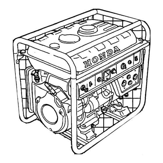
- Page 6 2. COMPONENT IDENTIFICATION VOLT METER VOLTAGE SELECTOR SWITCH AUTO-THROTTLE SWITCH ENGINE SWITCU OIL ALERT SWITCH DC Cl RCUIT PROTECTOR FIIFI VAIVF- AC RECEPTACLE RECOIL STARTER GRIP DC TERMINALS ENGINE OIL DRAIN PLUG (EMS45001...
- Page 8 1. Check the engine oil level. CAUTION: Engine oil is a major factor affecting engine performance service life, Non-detergent and S-stroke engine oils are not recommended. Use Honda 4-stroke oil, or an equivalent high detergent, premium quality motor oil certified to meet or exceed U.S.
- Page 9 NOTE: The Oil Alert System will automatically stop the engine before the oil level falls below the safe limit. However, to avoid the inconv.enience of an unexpected shutdown, it is still advisable to visually Inspect the oil level regularly. If the Oil Alert Switch is tripped, add oil to the top of the oil filler neck, re- set the Oil Alert Switch, and restart the engine according to instructions...
- Page 10 2. Check the fuel level. Use any brand of regular grade automotive gasoline (unleaded gasoline is preferred) with an antiknock index of 86 or higher as calculated using the Cost of Living Council formula (equal to 91 Research Octane Number or higher.) Never use an oil/gasoline mixture...
- Page 11 4. STARTING THE ENGINE NOTE: Make sure that the AC circuit breaker is OFF and that nothing connected to the DC terminals. The generator may be hard to start if a load is connected. AC CIRCUIT BREAKER DC TERMINALS...
- Page 12 [ MANUAL STARTING 1, Turn the fuel valve on. FUEL VALVE 2. Pull the choke rod out to CLOSE. CHOKE ROD 3. Make sure the Oil Alert switch is on. OIL ALERT @‘ITCH...
- Page 13 4. Make sure the auto-throttle switch is off, or more time will be required fc warm up. AUTO-THROTTLE SWITCH 5. Turn the engine switch on. ENGINE SWITCH 6. Pull the starter grip until compression is felt, then pull briskly. NOTE: Do not allow the starter grip to snap back.
- Page 14 7. Push the choke rod to OPEN as the engine warms up. CHOKE ROD 8. If auto-throttle will be used, turn the switch to “AUTO” after the engine has warmed up. AUTO-THROTTLE SWITCH...
- Page 15 [ ELECTRIC STARTING 1. Turn the fuel valve on. FUEL VALVE 2. Make sure the oil alert switch is on. 3. Make sure the auto-throttle switch is off, or more time will be required for warm up. AUTO-THROTTLE SWITCH...
- Page 16 4. Turn the engine switch to START and hold it there until the engine starts. NOTE: If a relay box is attached for remote control operation, make sure the switch on the relay box is turned off, or the engine will not start. 0 When the speed of the starter motor drops after a period of time, it is an indication that the battery should be recharged.
- Page 17 6. Turn the auto-throttle switch to AUTo after the engine has warmed up. AUTO-THROTTLE SWITCH The choke is operated automatically whenever a battery is connect- NOTE: ed to the generator’s starting circuit.
- Page 18 5. GENERATOR To prevent electrical shock from faulty appliances, the generator should be grounded. Connect a length of heavy wire between the ground terminal and the ground source. CAUTION: Limit operation requiring maximum power (EMS4000 : 4.0 kW, EMS4500 : 4.5 kW) to 30 minutes.
- Page 19 AC applications 1. Start the engine and make sure the pilot lamp comes on. If not, the filament may be burnt out. 2. Turn the voltage selector switch to either position as required. When the switch is turned to “12OV ONLY” position, you can use only 120V AC.
- Page 20 DC application The DC terminals may be used for charging 12 volt automotive-type batteries only. Batteries produce explosive gases. Keep sparks, flames, cigarettes away. To prevent the possibility of creating a spark near the battery, connect charging cables first to the battery, then to the generator, and disconnect cables first at the generator.
-
Page 21: Stopping The Engine
6. STOPPING THE ENGINE NOTE: To stop the engine in an emergency, turn the engine switch OFF. In normal use: 1. Turn the AC circuit breaker off and/or disconnect the charging leads at the DC terminals. AC CIRCUIT BREAKER 2. Turn the engine switch OFF. ENGINE SWITCH... - Page 22 3. Turn the fuel valve OFF. FUEL VALVE...
- Page 23 If the engine must be run, make sure the area is well ventilated. The ezhaust contains poisonous carbon monoxide gas. CAUTION: Use only genuine HONDA parts or their equivalent. The use of replacement parts which are not of equivalent quality may damage the generator.
- Page 24 Spark arrester NOTE (1) : Service more frequently when used in dusty areas. (2) : These items should be serviced by an authorized Honda dealer, unless the ’ owner has the proper tools and is mechanically proficient. See the Honda...
- Page 25 Tool kit The tools supplied are necessary for performing some periodic maintenance, simple adjustments and repairs. Always keep the kit with the generator. Changing oil Drain the oil while the engine is still warm to assure rapid and complete draining. 1.
- Page 26 Air cleaner service A dirty air cleaner will restrict air flow to the carburetor. To prevent carburetor malfunction, service the air cleaner regularly (page 22). Service more frequently when operating the generator in extremely dusty areas, Never use gasoline or low flash point solvents for cleaning the air cleaner element.
- Page 27 2. Wash the element in a non-flammable or high flash point solvent and dry it thoroughly. 3. Soak the element in clean engine oil and squeeze out the excess oil. 4. Reinstall the air cleaner element and the cover. ELEMENT...
- Page 28 Sediment cup service The sediment cup prevents dirt or water which may be in the fuel tank from entering the carburetor. If the engine has not been run for a long time, the cup should be cleaned. 1. Turn the fuel valve OFF. Remove the sediment cup. 2.
- Page 29 Spark plug service Recommended spark plug: BPR4HS-10 (NGK) W14FPR-ULlO (ND) To ensure proper engine operation, the spark plug ,must be properly gapped and free of deposits. 1. Remove the spark plug cover. 2. Clean any dirt from around the spark plug base. 3.
- Page 30 4. Use the wrench supplied in the tool kit to remove the spark plug. 5. Visually inspect the spark plug. Discard it if the insulator is cracked or chipped. 6. Measure the plug gap with a feeler gauge. The gap should be 0.9-l .O mm (0.035-0.039 in).
- Page 31 Spark arrester maintenance If the generator has been running, the muffler will be very hot. Allow it to cool before proceeding. CAUTION: The spark arrester must be serviced every 100 hours to maintain its efficiency. 1. Loosen the bolts and nuts and remove the muffler. 2.
-
Page 32: Transporting/Storage
8. TRANSPORTING/STORAGE When transporting the generator, turn the engine switch OFF and keep the generator level to prevent fuel spillage. Fuel vapor or spilled fuel may ignite. Before storing the unit for an extended period: 1. Be sure the storage area is free of excessive humidity and dust. - Page 33 d. Drain the carburetor by loosening the drain screw. Drain the gasoline into a suitable container. DRAIN SCREW e. Slowly pull the starter grip until resistance is felt. At this point, the piston is coming up on its compression stroke and both the intake and exhaust valves are closed.
-
Page 34: Troubleshooting
9. TROUBLESHOOTING A. When the engine will not start: 1. Is there enough fuel? 2. Is the fuel valve on? 3. Is gasoline reaching the carburetor? To check, loosen the drain screw with the fuel valve on. If any fuel is spilled, make sure the area is dry before testing the spark plug or starting the engine. - Page 35 If there are no sparks, replace the plug and check again. If OK, try to start the engine according to the instructions. 8. If there is still no spark or if the engine still does not start, take the gen- erator to an authorized Honda dealer.
- Page 36 B. When the engine starts but stops immediately: Is there enough oil in the crankcase? If not, the oil alert switch will turn off after starting. C. No electricity at the AC receptacles: 1. Are the AC circuit breakers on? 2.
-
Page 37: Specifications
Dimensions Length x Width x Height 65Ox425x575mm (25.6 x 16.7 x 22.6 in) Dry weight 85.0kg( 187.4lb) Engine Honda G E400 Model 4Stroke, side valve, 1 cylinder Engine Type 406 cc (24.8 cu in) Displacement [B6 x 70 mm (3.4 x 2.8 in)] (Bore x Stroke) 6.8: 1... - Page 38 11. WIRING DIAGRAM <EMS4000> .... ________________ ------------ ----------- ....J>G L---------- __--___ -------------,...
- Page 39 B ..BLACK G ..GREEN R ..WHITE : ..LIGHT GREEN .PINK -~.. L... LL. ____. --.-.__._ L::::: .BLUE -BLOCll Y..YELLOW .
- Page 40 12. INSTALLATION OF Ol?TIONAL PARTS Battery mount kit 1. Remove and retain the two bolts attaching the upper frame to the lower frame on the generator side. Position the battery guards on the lower frame and install using the bolts retained. (See page 39) 2.
- Page 41 STARTER GROUND’ ’ CABLE BATTERY’ TRAY...
- Page 42 Remote control The generator may be adapted for remote control operation with an optional kit. 1. Position the relay box on the tabs of the pipe frame on the right (generator) side and attach it with the two 6 mm screws. 2.
- Page 43 Remote control operation (STARTING) 1. Turn the fuel valve on. 2. Turn the oil alert switch on. 3. Turn the auto-throttle switch off. 4. Turn the ignition switch key off or remove it from the generator. 5. Turn the relay switch on. RELAY SWITCH 6.
- Page 44 7. Depress the starter button until the engine starts. Be sure that pilot lamp comes on when the engine starts. NOTE: Do not hold the starter button on for more than 15 seconds at a time. If the engine has not started by then, check through the starting procedure above to be sure that all switches, valves, etc are in the correct position.
-
Page 45: Warranty Service
Your purchase of a Honda engine is greatly appreciated by both the dealer and American Honda Motor Co., Inc. We want to assist you in ev- ery way possible to assure your complete satisfaction with your... - Page 46 When you write or call, please provide the following information: • Model and serial numbers • Name of the dealer who sold the Honda power equipment to you • Name and address of the dealer who services your equipment •...
- Page 47 L/.<..Jy American Honda Motor Co.. Inc. Customer Relations Depanment P.O. Box 420 Gardena. CA 90247-0642 (213) 604.2400 EASTERN ZONE SERVICE OFFICE (includes Puetto Rim) American Honda Motor Co., Inc. Customer Relations Depxtmern 1500 Morrison Parkway Alpharetta. GA 30201 (404) 442.zoo0...
Need help?
Do you have a question about the EMS4000 and is the answer not in the manual?
Questions and answers