Table of Contents
Advertisement
D10D
Model No.
INSTALLATION AND OPERATION MANUAL
D10D – In Dash Digital Depth Sounder with Transom/Glue-In Transducer
SAFETY INFORMATION:
•
Periodically wipe the face with a dry cloth. Do not use abrasives or
solvents on this device.
•
Only qualified personnel should perform repairs or servicing not covered
in this manual.
•
The LCD used in the product is made of glass. Therefore, it can break
when the product is dropped or impacted.
•
Keep this product away from heat sources such as radiators, heaters,
stoves and other heat generating sources.
temperatures above 150° F (65° C).
•
Shade the LCD during storage. Do not expose LCD to direct sunlight for
extended periods of time. Use the supplied cover at all times during
storage.
NOTES, NOTICES, AND CAUTIONS
WARNING: Indicates a potential for property damage, personal injury or
death.
IMPORTANT: Indicates potential damage to the device and tells you how to
avoid it.
NOTICE: Indicates important information that helps you make better use of
the device and tells you how to correct a performance problem.
INFORMATION: Indicates resources to obtain the proper information to help
you make the most of your device.
Read this manual completely before attempting to use or
install your device. Visit our Customer Service Center on our
website for advanced troubleshooting and technical support.
This depth sounder should not be used as a navigational aid
to prevent grounding, boat damage, or personal injury. Always
operate the boat at slow speeds in unfamiliar water, or if you
suspect shallow water or submerged objects.
w w w . h a w k e y e e l e c t r o n i c s . c o m
To ensure safety and many years of trouble-free
operation of your product, please read this
manual carefully before using this product.
I
:
NFORMATION
W
:
ARNING
Do not store in extreme
Advertisement
Table of Contents
Troubleshooting

Related Manuals for Hawkeye Mfg D10D


Summary of Contents for Hawkeye Mfg D10D
- Page 1 D10D Model No. INSTALLATION AND OPERATION MANUAL D10D – In Dash Digital Depth Sounder with Transom/Glue-In Transducer To ensure safety and many years of trouble-free operation of your product, please read this manual carefully before using this product. SAFETY INFORMATION: •...
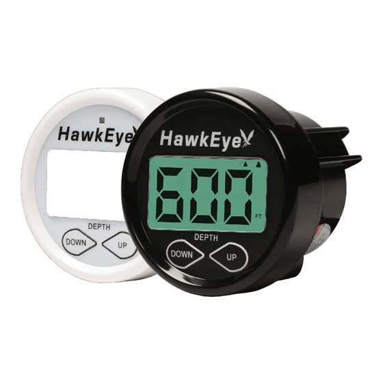
- Page 2 PARTS SUPPLIED IN PACKAGING The following parts should be included with the display: • Digital Depth Sounder Display • White and Black Faces and Bezels (optional on some models, see package for details) • Display Sun Cover (optional on some models, see package for details) •...
- Page 3 • Shallow draft boats to prevent accidental damage to the transducer from intentional or unintentional ground. • NON-CORED hulls or aluminum hulls thinner than 1/8”. • Inboard vessels that have a lot of running gear that creates significant turbulence. OTICE Glue-in mounting of the transducer is NOT suitable for all vessels.
- Page 4 3. Cut out the 2-inch hole using the 2” hole saw. 4. Seal any exposed wood with a marine sealant. 5. Insert the display from the front of the panel, feed the wires through the bracket and install the bracket and locking nut from the rear of the panel.
- Page 5 2. Connect the RED wire in the harness to a positive (+) 12 Volt switchable power source (key switch, on/off switch, terminal block, etc). OTICE Never “Twist-On” “Automotive” type connectors. These connectors do not form a solid electrical connection and are more likely to corrode. STEP 4 Testing the Display Installation Before continuing with your installation, you should test the unit to make sure the...
- Page 6 6. Visit our Customer Service Center on our website or call 888-766-7276 for advanced technical support. OTICE The fuse used in the In Dash Depth Sounder is a .25A, 250V fuse. Do not rely on a visual inspection of the fuse to determine if it is functioning.
- Page 7 4. Holding down the key will change the value in 9 foot increments per second. 5. After the desired setting is achieved, the display will return to normal operation after 5 seconds. 6. The indicators will now be illuminated to indicate that a shallow water alarm is set.
- Page 8 operate safe (typically referred to as your vessel’s “Draft”) For Example: If your boat’s draft is 3 feet, the Keel Offset feature should be set to 3 feet. The device will then subtract 3 feet from the actual depth reading and display this figure as the depth.
- Page 9 2. Release the Keys. 3. To set the units to FEET press the “UP” key. “FT” will flash on the Display. 4. To set the units to METERS press the “DOWN” key. “M” will flash on the Display. 5. The display will return to the normal operation mode automatically after five seconds.
- Page 10 • Hull deadrise angle below 30°. • Transom angle from 3-20°. OTICE To get a good “view” of the mounting location, while the vessel is out of the water, position yourself at the transom and look at the bottom of the hull towards the bow. Using illustrations A thru I, note anything that could interrupt the clean flow of water to the transducer mounting location.
- Page 11 STEP 1 Choosing a Mounting Location To obtain the best performance, the transducer should be mounted in a location where the water flow beneath the hull is aeration and turbulence-free. Try to mount the transducer as close to the centerline of the boat as possible. Consult the boat manufacturer best in-hull...
- Page 12 Mounting Location “DONT’s” OTICE To deliver consistent, accurate readings, the transducer must have continuous supply non- turbulent water. Do not mount the transducer in an area of turbulence or bubbles. Never install the transducer where the boat may be supported during trailering, launching, hauling, or storage.
- Page 13 STEP 2 Assembling the Transom Mount Bracket 1. With the Locking Tab in the up position, align the transducer and bracket, then slide the transducer into the Pivot Bracket until it cannot slide any further (minimal force is required) (illustration A). 2.
- Page 14 4. The bracket is designed for a standard 13° transom angle. To determine if the plastic shim is needed, position the transducer at the desired location. Using a straight edge, compare the underside of the transducer relative to the underside of the hull. The stern (trailing edge) of the transducer should be 1/16"...
- Page 15 STEP 4 Cable Routing Route the transducer cable over the transom, through a deck or splash-well drain hole or through a new hole drilled in the transom. If a new hole is required, it MUST be drilled well above the waterline. To Drill a Cable Pass Through: 1.
- Page 16 OTICE If you need to increase the length of the transducer cable order part # 8000-90 from our website or toll free at 888-766-7276. Strip back the rubber cable cover 1” (28 mm) exposing the three internal wires (blue, black, and bare) on your transducer. Using a soldering iron, solder the blue, white and bare wires from the 8000-90 extension cable to the corresponding wires on your transducer.
- Page 17 of the boat over the base of the transducer. The water should be "Clean" with very little turbulence (air bubbles). If there are any air bubbles or turbulence seen passing underneath the transducer, move the transducer farther down on the transom bracket. If the performance does not improve, move the transducer to "Clean Water"...
- Page 18 STEP 1 Choosing a Mounting Location OTICE If your hull is not SOLID fiberglass or up to 1/8th” Aluminum, this transducer CAN NOT be mounted in-hull. Refer to the Transom Mounting Instructions, visit our Customer Service Center on our website, or call 888-766-7276 to inquire about exchanging the transducer. Since the hull absorbs acoustic energy, transmitting through hull...
- Page 19 Mounting Location “DONT’s” OTICE To deliver consistent, accurate readings, the transducer must have continuous supply non- turbulent water. Do not mount the transducer in an area of turbulence or bubbles. Never install the transducer where the boat may be supported during trailering, launching, hauling, or storage.
- Page 20 OTICE To get a good “view” of the mounting location, while the vessel is out of the water, position yourself at the transom and look at the bottom of the hull towards the bow. Using illustrations A thru I, note anything that could interrupt the clean flow of water to the transducer mounting location.
- Page 21 5. Remove the transducer from the water. Use one of the methods below to test the depth readings with the transducer at the desired in-hull location selected in Step 1. If the hull surface is not smooth, sand it with 30 grit sandpaper until a smooth surface is obtained.
- Page 22 11. DO NOT proceed to the next step until you are satisfied with the readings. If you have difficulties please visit our Customer Service Center on our website or call 888- 667-2767 for technical assistance. STEP 3 Gluing the Transducer In Place 2-Part, Slow Cure Epoxy All surfaces to be bonded must be smooth, clean and dry.
- Page 23 Allow the adhesive to cure as per the manufacturer’s instructions. OTICE Try to align the transducer so that the point is aimed at the bow of the vessel. STEP 4 Routing the Cable 1. After the adhesive has cured, route the cable the mounting location of the depth sounder transducer plug.
- Page 24 OTICE If “---” appears on the display, make sure that there is at least 2.5 feet of water between the bottom of the transducer and the bottom of the water body. Also make sure that the Keel Offset feature is turned OFF. 3.
- Page 25 TROUBLESHOOTING AND FREQUENTLY ASKED QUESTIONS 24-Hour Technical Support is available online at hawkeyeelectronics.com. Search our online Knowledgebase for the latest troubleshooting and FAQ’s, or post your own question for our support staff. For one-on-one support please email customerservice@norcrossmarine.com. NFORMATION If you have questions about this device please visit our Customer Service Center on our website or call us toll free at 888-766-7276.
- Page 26 Poor Performance: If you are not happy with the performance of your depth sounder, please visit our website or call 888-766-7276 for technical support. Rest assured that this depth sounder is engineered to the highest standards and is part of the best selling family of depth sounders in the world.
- Page 27 WARRANTY This device is covered by a 2 Year Limited Warranty. To be eligible for warranty coverage, you must register your product within 15 days of purchase. Visit our website for warranty details and to register. • To Activate Your Warranty: •...
- Page 28 ARNING © 2010 NorCross Marine Products Inc., All Rights Reserved. ALL unauthorized copying of the content of this document without the expressed written consent of NorCross Marine Products, Inc is strictly forbidden. NOTES w w w . h a w k e y e e l e c t r o n i c s . c o m...
Need help?
Do you have a question about the D10D and is the answer not in the manual?
Questions and answers