Table of Contents
Advertisement
Quick Links
Advertisement
Table of Contents

Related Manuals for ESI MaXiO series


Summary of Contents for ESI MaXiO series
- Page 1 High End 24-bit/192kHz Audio/MIDI Interface System Manual...
- Page 2 ESI - Copyright © 2005-2008 Revision 3, June 2008 www.esi-audio.com...
-
Page 3: Table Of Contents
MaXiO series System Manual INDEX 1. Introduction..........................5 1.1 About this manual ........................5 1.2 Key Features........................... 6 1.2.1 MaXiO PCI/PCIe host card ....................6 1.2.2 EX8000 2U Rack ......................6 1.2.3 MaXiO 032 breakout box ....................6 2.1 MaXiO PCI / PCIe host card....................7 2.1.1 E.D.I connector ......................... - Page 4 MaXiO series System Manual 5.1 Pull Down Menu ........................27 5.2 Input Section......................... 28 5.2.1 Input signal path block diagram..................30 5.3 Output Section........................31 5.3.1 Master Section ........................ 32 5.3.2 Master & Output signal path block diagram..............33 5.4 MaXiO display section......................33 5.4.1 MaXiO State ........................
-
Page 5: Introduction
The MaXiO 032 can be expanded via its E.D.I (ESI Digital Interface) connectors into a full MaXiO XD system by adding one or several EX8000 units. -
Page 6: Key Features
High-end quality 24-bit / 192 kHz ADC with 123dB(a) dynamic range · High-end quality 24-bit / 192 kHz DAC with 120dB(a) dynamic range · 8 balanced analog inputs with combo (XLR / TRS) connectors featuring ESI’s newly · developed 'XD-PRE' high precision & ultra low noise (-135.5dBu) microphone ·... -
Page 7: Maxio Pci / Pcie Host Card
2.1 MaXiO PCI / PCIe host card 2.1.1 E.D.I connector E.D.I is ESI’s exclusive digital audio transfer protocol that delivers an 8 channel audio stream (with up to 24-bit / 192 kHz). E.D.I uses an IEEE1394/FireWire cable for the connection of E.D.I compatible devices like EX8000 to the MaXiO PCI/PCIe host card. -
Page 8: Connector
MaXiO series System Manual 2.1.2 M.D.I connector The M.D.I connection can handle 32 digital input and 32 digital output streams for the extension of MaXiO 032 breakout box. * In the basic MaXiO XD system, the MaXiO PCI/PCIe card connects to the special M.D.I breakout cable (described below). -
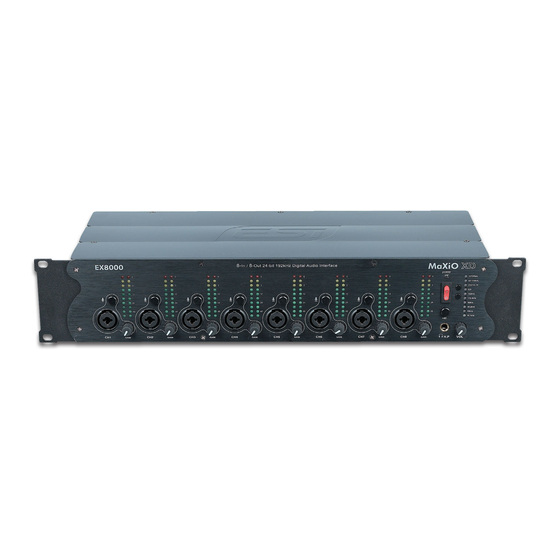
Page 9: Front Panel Power Section
MaXiO series System Manual can be amplified with 48dB maximum, line level signals with up to 30dB. Analog Input / Output Level Meter The two level meters indicate the signal level for the analog inputs and outputs. The level meter on the left shows the input signal;... -
Page 10: Back Panel Clock Section
MaXiO series System Manual PCI/PCIe host card. Clock Select Button 2 When EX8000 is working in stand alone mode, you can choose the sample rate with this button (44.1 ~ 192 kHz). This function is not available when EX8000 is connected to the MaXiO PCI/PCIe host card. -
Page 11: Digital I/O (Back Panel)
MaXiO series System Manual 2.2.7 Digital I/O (Back Panel) E.D.I Connector E.D.I Connector IN: connection to MaXiO PCI/PCIe (with a standard IEEE1394 cable). E.D.I Connector THRU: this connector is reserved for future expansion. ADAT Optical Input / Output EX8000 has 8 channel ADAT optical I/O connectors. You can connect EX8000 to devices such as digital mixers or ADAT multichannel recorders equipped with optical ADAT connectors. -
Page 12: Breakout Cable (For Maxio Xd Only, Not Included In Maxio 032)
MaXiO series System Manual 2.3 M.D.I breakout cable (for MaXiO XD only, not included in MaXiO 032) 2.3.1 Word Clock I/O This connector allows you to synchronise the MaXiO PCI/PCIe host card via Word Clock (BNC) with other audio devices. You can synchronise other devices via the Word Clock output (FS / 256xFS) and you can also synchronise the MaXiO PCI/PCIe host card to other devices via the Word Clock input. -
Page 13: Maxio 032 Breakout Box
MaXiO series System Manual 2.4 MaXiO 032 breakout box MIDI indicator & Phontom power 1. Front Channel Section Headphone MIDI I/O 8 x ADAT Digital I/O 12-13 S/PDIF & Word Clock M.D.I connector 13 Analog outputs (XLR & 1/4“) 2.4.1 Front Panel Input Channel Section Analog Balanced XLR / TRS (Combo) Input Connector MaXiO 032 breakout box provides 2 combo connectors (XLR and 1/4"... -
Page 14: Midi Signal Leds & Phantom Power
MaXiO series System Manual Input Gain Control Controls the amount gain applied to the input signal from the XLR or TRS connector of specific channel. Microphone signals can be amplified with 48dB maximum, line level signals with up to 30dB. Analog Input Level Meter LEDs The meters indicate the signal level for the analog inputs. -
Page 15: Digital I/O
MaXiO series System Manual 2.4.4 Digital I/O MaXiO 032 has 32 channel ADAT optical I/O connectors. You can connect MaXiO 032 to devices such as 4 ADAT compatible devices. One ADAT cable transfers 8 channels with max. 48 kHz. Digital S/PDIF (RCA) Input / Output MaXiO 032 has stereo S/PDIF inputs and outputs (RCA) for coaxial digital connection. -
Page 16: Hardware Installation
MaXiO series System Manual 3. Hardware Installation 3.1 Installation of MaXiO PCI/PCIe host card The MaXiO PCI/PCIe host card and other components in your computer can easily be damaged by electrical shocks. You need to use an anti-static device that can discharge the static electricity of your body to avoid potential static damage to the cards. -
Page 17: Ex8000 Connection
MaXiO series System Manual removing the PCI/PCIe slot faceplate Put the MaXiO PCI/PCIe host card into the slot and make sure it is placed in correctly. Insert the card into the slot and then tighten the screw. Then you can close the computer case. -
Page 18: Maxio 032 Connection
MaXiO series System Manual 3.3 MaXiO 032 connection After the MaXiO PCI/PCIe host card is installed in the PCI/PCIe slot, you should connect MaXiO 032 to the card using the supplied M.D.I cable. Start by connecting the MaXiO breakout box with the M.D.I In connector on MaXiO breakout box with the M.D.I port on the MaXiO PCI/PCIe host card as shown on the picture below. - Page 19 MaXiO series System Manual...
-
Page 20: Driver Installation
MaXiO series System Manual 4. Driver Installation After completing the hardware installation of your MaXiO, you need to install its driver. The installation steps in Windows 2000 and Windows XP vary, but they are similar between the different versions of Windows. The installation steps shown below are based on Windows XP installation. - Page 21 3. During installation, you will be prompted with a message warning that the driver software has not passed Windows Logo testing. Select Continue Anyway and proceed with the installation. The driver is completely tested and verified by ESI, and safe to use. 4. The MaXiO EWDM Controller driver will be installed.
- Page 22 MaXiO series System Manual 5. Keep going to install follow the instructions on screen. Other devices (such as MaXiO EWDM Wave-1) are installed now after each other. Check the screen shots for reference.
- Page 23 MaXiO series System Manual...
- Page 24 MaXiO series System Manual...
- Page 25 MaXiO series System Manual When the system asks you to restart the computer (which happens on some computers), just ignore the requests and continue to install. When all the necessary device drivers are installed and the system is not asking you to install any further drivers, restart the computer manually.
- Page 26 MaXiO series System Manual After you restart Windows, please confirm if the icon is visible in the system tray of the task bar. Then go to My computer -> Control panel -> System -> Device Manager. Check the devices under Sound, video and game controllers, if they are installed correctly.
-
Page 27: Maxio Control Panel
File - Exit This will close the MaXiO Control Panel window but it will not shut down the control panel. You can always relaunch the control panel by clicking ‘ESI’ icon on the system tray. Config – Mouse Wheel Controls the increment at which the volume is adjusted when using a mouse wheel. The adjustment... -
Page 28: Input Section
MaXiO series System Manual Config – Latency Here you can choose between different buffer sizes. There are 2 different sections: First buffer sizes from 128 samples (3 milliseconds with 44.1 kHz) to 2048 samples (48 milliseconds with 44.1 kHz). Secondly there are the ultra latency settings: buffer sizes from 96 Samples (2,5 milliseconds) to 32 Samples (0.75 milliseconds). - Page 29 MaXiO series System Manual Port Selection The 32 input channels of the MaXiO XD system are grouped into 4 sections (ports) with 8 input channels each. For each group of 8 channels (each port), you can select either the corresponding E.D.I input (1 to 4) or the signals from the M.D.I connector by clicking on the IN PORTx label.
-
Page 30: Input Signal Path Block Diagram
MaXiO series System Manual Please note that when you select the analog or S/PDIF input channels, the input signals from that specific channel pair from the E.D.I or M.D.I multichannel ports are no longer used. Please keep in mind that the M.D.I analog and S/PDIF input selection buttons should not be used if you do not want to use the S/PDIF or analog input signals from the device or cable connected to the M.D.I port –... -
Page 31: Output Section
MaXiO series System Manual 5.3 Output Section Master Output Select Port Selection E.D.I Device Detection Master Fader Output Level Meter MME Channel Mapper M.D.I Analog Output M.D.I S/PDIF Output Master to Analog & Output Monitor Buttons S/PDIF Button The right section of the control panel windows shows the status and the control features for the output channels. -
Page 32: Master Section
MaXiO series System Manual the MaXiO 032 breakout box provides two analog output channels and a digital S/PDIF output. The M.D.I breakout cable that is supplied with the basic MaXiO XD system provides a digital S/PDIF output but no analog output channels. One channel pair each can be assigned to these analog outputs and to that S/PDIF output. -
Page 33: Master & Output Signal Path Block Diagram
MaXiO series System Manual : Monitoring enabled, signal will be mixed to mono With the circle on the right, you can disable/enable monitoring for all input (or playback) channels simultaneously. 5.3.2 Master & Output signal path block diagram E.D.I Connector #1 E.D.I Connector #2 E.D.I 1 E.D.I 2... -
Page 34: Maxio State
MaXiO series System Manual 5.4.1 MaXiO State This panel shows you the -currently active- most important settings of the MaXiO PCI/PCIe host card. 5.4.2 System Clock Internal: selects the internal clock generator on the MaXiO PCI/PCIe host card to provide the system clock for the complete MaXiO XD system. -
Page 35: I/O Config
MaXiO series System Manual the device connected to the Word Clock input is configured as clock master. You can choose between FS (Word Clock) or 256FS (Super Clock) settings. 5.4.3 I/O Config Analog: This where you adjust the analog output level of the analog output channel of the MaXiO PCI/PCIe host card. - Page 36 MaXiO 032 breakout box to one MaXiO PCI/PCIe host card, you need to change the CH. Limit setting before you can use more than 8 input and 8 output channels. please always check our website (www.esi-pro.com) for updated information about system ·...
-
Page 37: The Ex8000 Control Panel
MaXiO series System Manual 5.5 The EX8000 control panel Each EX8000 connected to the MaXiO PCI/PCIe host card has its own control panel windows that you can access by double clicking on its name in the MaXiO Control Panel. Clock Setting: Defines the system clock of the specific EX8000 unit. Internal: Use the internal clock inside EX8000. - Page 38 MaXiO series System Manual ETC Setting ADAT S/MUX Mode: - Normal (44 kHz ,48 kHz – 8 channels) - SMUX 1 (96 kHz – 4 channels) - SMUX 2 (192 kHz – 2 channels) LED Display: - Mode 1 (shows a continuous graphical representation of the level) - Mode 2 (continuous display with level meter peak hold) - Mode 3 (shows a dot representation of the level) - Mode 4 (the level meter will hold the maximum level that was reached)
- Page 39 MaXiO series System Manual Digital Audio Input Port Select: This is where you can switch between the coaxial S/PDIF digital input and the XLR AES/EBU digital input for each of the 4 digital inputs available in each format. PLL status: Shows if an S/PDIF (or AES/EBU) connection is made. If Lock is displayed, an S/PDIF (or AES/EBU) signal is detected at the specific input.
-
Page 40: Applications Setup
MaXiO series System Manual 6. Applications Setup This chapter contains basic configuration examples for some popular software applications. Please also refer to the manual of the audio software you use for detailed information. 6.1 Windows Multimedia setup The Windows Multimedia setup is required if you want to use your MaXiO system as the main sound device for Windows multimedia applications. -
Page 41: Cubase And Nuendo
MaXiO series System Manual 6.2 Cubase and Nuendo After launching Cubase or Nuendo, go to Device -> Device Setup -> VST Multitrack. Select ASIO 2.0 –MaXiO as ASIO device. Then go to Default MIDI Ports and select MaXiO MIDI. Note: clicking the ASIO Control Panel button will not do anything here. -
Page 42: Cakewalk Sonar
MaXiO series System Manual 6.3 Cakewalk SONAR There are few steps to configure SONAR, which supports either WDM or ASIO drivers. After launching SONAR, go to Options > Audio. If you prefer the shown in the following picture: WDM/KS mode, change the settings as Note that the input and output drivers have to match each other. - Page 43 MaXiO series System Manual Then change all the settings as shown on the following picture: Note: enabling SONAR’s software input monitoring may introduce feedback loops. You MUST · disable / mute MaXiO input monitoring before using SONAR’s software input monitoring.
-
Page 44: Wavelab
MaXiO series System Manual 6.4 Wavelab After launching Wavelab, go to Options -> Preference -> Audio Card. Select either MME-WDM MaXiO Stereo Wave(SPDIF/PCM) or ASIO 2.0 –MaXiO. MME configuration ASIO configuration... -
Page 45: Tracktion
MaXiO series System Manual 6.5 Tracktion The MaXiO XD system comes bundled with the full version of Tracktion – a professional recording and MIDI production software by Mackie / Raw Material Software. After launching Tracktion, select Settings then go to the audio devices tab. Choose ASIO 2.0 - MaXiO as playback and record device as shown below. -
Page 46: Directwire 3.0
7.1 What is DirectWIRE? DirectWIRE is a 100% purely digital wire! DirectWIRE is a driver technology, developed by ESI, which can be used for routing audio streams internally within applications using EWDM Audio MIDI Drivers. With the DirectWIRE router, an application can record from other application’s audio outputs without external wiring or any loss of data when they are running at the same time. -
Page 47: Directwire Examples
MaXiO series System Manual The number on the row represents the input or output port. The columns represent ins and outs (on and off) of the respected drivers. Patch the virtual cables from one point to another as you drag the mouse. INPUT section is a new feature of DirectWIRE 3.0. - Page 48 MaXiO series System Manual Example 2. Recording from WinAmp(MME) to SONAR(WDM): Example 3. Recording from WinAmp(MME) to Cubase, Logic, Nuendo(ASIO): Example 4. Recording from GigaStudio(GSIF) to SONAR(WDM):...
- Page 49 MaXiO series System Manual Example 5. Recording from GigaStudio(GSIF) to Cubase(ASIO): Example 6. Let's say you want to quickly dub some vocal over an audio track. It's very simple with DirectWIRE 3.0, you just have to make connections similar to these:...
-
Page 50: Technical Specifications
MaXiO series System Manual 8. Technical Specifications MaXiO PCI host card General PCI Interface 32bit, PCI Bus-Mastering support PCI slot compatibility – designed to suit +3.3V and/or +5V PCI slot Audio Total 32-in / 32-out, 24bit, audio interface Full Duplex - Simultaneous Record / Playback System Clock Support Internal (44.1, 48.0, 88.2, 96.0, 176.4, 192.0 kHz), Word clock, Digital In, E.D.I MIDI I/O... - Page 51 MaXiO series System Manual EX8000 General Type 19" rack mounted, digital audio interface Audio Total 8-in / 8-out, 24bit, audio interface System Clock Support Internal (44.1, 48.0, 88.2, 96.0, 176.4, 192.0 kHz), Word Clock, Digital In, E.D.I WORD Clock IN FS / 256*FS, BNC Connector Power AC IN 100V ~ 240V, 50Hz ~ 60Hz, 30W...
-
Page 52: Maxio 032 Breakout Box
MaXiO series System Manual MaXiO 032 breakout box General Type Half rack type, M.D.I Based Digital audio interface Audio Total 32-in / 32-out, 24bit, audio interface System Clock Support Internal (44.1, 48.0, 88.2, 96.0, 176.4, 192.0 kHz), Word Clock, Digital In, E.D.I MIDI I/O 1-in / 1-out 16 MIDI channel , Standard MIDI 5-pin DIN WORD Clock I/O... -
Page 53: General Information
System Manual 9. General Information Trademarks ESI, and MaXiO are trademarks of Ego Systems Inc. and ESI Audiotechnik GmbH. Windows is a trademark of Microsoft Corporation. Other product and brand names are trademarks or registered trademarks of their respective companies.
Need help?
Do you have a question about the MaXiO series and is the answer not in the manual?
Questions and answers