Table of Contents
Advertisement
Quick Links
Advertisement
Table of Contents

Related Manuals for dbx 576


Summary of Contents for dbx 576
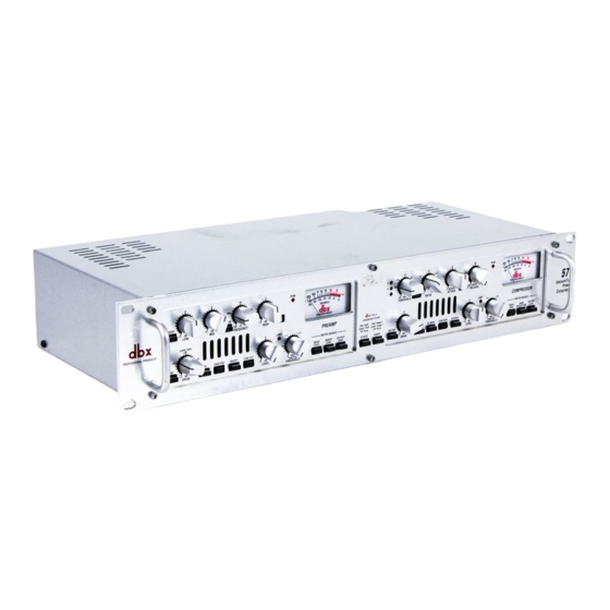
- Page 1 Vacuum Tube Preamplifier & Compressor Owner’s Manual Version 1.0...
-
Page 2: Electromagnetic Compatibility
This equipment may require the use of a different line cord, attachment plug, or both, depending on the available power source at installation. If the European Contact: Your Local dbx Sales and Service Office or attachment plug needs to be changed, refer servicing to qualified service personnel who should refer to the table above. -
Page 3: Table Of Contents
Table of Contents Introduction ........................2 Features........................2 Inspection ........................3 Warranty........................3 Connections.........................4 Preamp Controls ......................5 Compressor Controls ....................10 Rear Panel: Preamp....................14 Rear Panel: Compressor ..................16 Specifications ......................17 Settings Page......................20... -
Page 4: Introduction
To ensure years of trouble-free oper- ation, each dbx 576 must pass a rigorous set of performance tests and a 24-hour burn-in period before it is shipped from the factory. -
Page 5: Inspection
If any of these items are missing, contact dbx customer service at (801) 568-7660. Warranty This warranty is valid only for the original purchaser and only in the United States. We warrant dbx products against defects in materials or workmanship for a period of two years from the date of orig- inal purchase for use, and agree to repair or, at our option, replace any defective item, except exter- nal power transformers, without charge for either parts or labor. -
Page 6: Connections
Connections To connect the 576 to your system, refer to the following steps: ¥ Turn off all equipment before making any connections. ¥ Mount the 576 in a rack with the rack screws provided. The 576 can be mounted above or below anything that does not generate excessive heat. -
Page 7: Preamp Controls
Preamp Controls Figure 1: Preamp Section of the front panel INSERT switch This switch enables the rear panel insert loop by inserting any device connected to the Send and Return jacks into the signal path. The insertion point is post-tube, pre-EQ. See page 15 for more details on the Insert feature. - Page 8 Preamp Controls (cont.) EQ switch This switch enables the equalizer. When the equalizer is disabled, the EQ circuit is hardwire bypassed. This switch allows you to instantly assess the effect of your EQ settings. PEAK led This red led illuminates when the 576Õs internal signal level is within 3 dB of clipping. The signal level is monitored at all critical stages of the circuit.
- Page 9 ª Appropriate use of it can protect your gear while keeping the signal free of artifacts. Peak Plus also ª serves to prevent digital overload when used in conjunction with the dbx Type IV Conversion System option. DRIVE LEVEL switch This configures the meter to show the signal level at the input to the vacuum tube.
- Page 10 0 VU corresponds to +4 dBu output. When the rear switch is set to -10 dBV, a meter reading of 0 VU corresponds to -10 dBV output. DITHER switch ª This switch becomes active only when the optional dbx Conversion System digital output TYPE IV ª...
-
Page 11: Compressor Controls
Compressor Controls Figure 2: Compressor Section of the front panel + 0 - THRESHOLD leds: ¨ The Ò+Ó led illuminates when the signal is above the OverEasy portion of the compression curve ¨ and that the full compression ratio is in effect . If OverEasy is disabled, this led indicates that the signal is above the level set by the Compressor Threshold control and that compression is occuring. - Page 12 The switch lights indicating the attack and release times are being automatically adjusted in a program-dependent fashion. Enabling the Auto function duplicates the Òclassic dbx soundÓ of the 576Õs forerunners which have become standards in the industry.
- Page 13 Compressor Controls (cont.) RELEASE control: The Release control sets how fast the compression circuit returns the input to its original level. The release rate is from 250 dB/sec where compression follows the envelope of the program material very tightly to 5 dB/sec for very smooth compression. UNLINK Switch: This switch determines whether the input to the Compressor section comes from the CompressorÕs line input jack or from the output of the 576Õs Preamp.
- Page 14 Compressor Controls (cont.) BYPASS switch This switch bypasses the compression section completely. The input is ÒhardwiredÓ to the output bypassing the tube amplification and VCA circuitry. This feature is very useful for setting optimum compression and gain settings because it gives you an instant reference to the amount of effect youÕve introduced to your signal.
-
Page 15: Rear Panel: Preamp
Rear Panel: Preamp WIRING SCHEME All of the input and output connectors are Òpin 2 hotÓ meaning that pin number 2 on the XLR con- necting cables carries the positive side of the balanced signal. Pin number 3 is ÒcoldÓ, carrying the negative polarity and pin 1 is the shield. - Page 16 This would generally be used to take advantage of the 576Õs digital output option. A signal from your microphone or instrument could be preamplified by the 576, processed externally through the INSERT I/O and returned to the 576 to be passed along to the high-resolution dbx TYPE ª...
-
Page 17: Rear Panel: Compressor
Rear Panel: Compressor LINE INPUTS Both XLR and TRS 1/4Ó connectors allow balanced or unbalanced line-level devices to be connect- ed to the input of the 576Õs Compressor section. The nominal input level can be set to either +4 dBu or -10 dBV with the +4 dBu/-10 dBV switch. -
Page 18: Specifications
Specifications PREAMP Microphone Input: Connector: Female XLR Pin 2 hot Type: Electronically balanced/unbalanced Impedance: 1.70 k½ Optimum Microphone Impedance: 150 - 200 Maximum Input Level: > +13 dBu, or +33 dBu with 20 dB pad engaged CMRR: > 115 dB at 60 Hz, > 110 dB at 1 kHz, > 75 dB at 10 Line Inputs: Connectors: Female XLR Pin 2 hot and TRS 1/4Ó... - Page 19 Specifications (cont.) HIGH Frequency: 12 kHz, shelving filter MID Frequency: Sweepable from 100 Hz to 8 kHz, bandwidth 1.5 octaves (WIDE) or 0.5 octaves (Narrow) Gain (all bands): Sweepable from -15 to +15 dB. COMPRESSOR Threshold Range: -40 dBu to +20 dBu Ratio: 1:1 to inf.
- Page 20 Specifications (cont.) THD + Noise: 0.04% typical at 0 dBu out, 1kHz, 33 dB gain (Drive control at minimum, Level control at maximum) 3.5% typical at +21 dBu out, 1kHz, 35 dB gain (tube saturation with Drive and Level controls at 50%) Deviation From Linear Phase: <...
-
Page 21: Settings Page
576 Settings Page Photocopy this page and mark the settings you use for your sessions. Session: Date: Comments: Session: Date: Comments:... - Page 22 8760 South Sandy Pkwy. Sandy, Utah 84070 Phone: (801) 568-7660 Fax: (801) 568-7662 IntÕl Fax: (603) 672-4246 Questions or comments? E¥mail us at: customer@dbxpro.com or visit our World Wide Web home page at: www.dbxpro.com...
Need help?
Do you have a question about the 576 and is the answer not in the manual?
Questions and answers