Advertisement
Quick Links
Advertisement

Summary of Contents for dbx 586
- Page 1 ¨ Vacuum Tube Preamplifier OwnerÕs Manual...
-
Page 2: Electromagnetic Compatibility
This equipment may require the use of a different line cord, attachment plug, or both, depending on the available power source at installation. If the European Contact: Your Local dbx Sales and Service Office or attachment plug needs to be changed, refer servicing to qualified service personnel who should refer to the table above. - Page 3 ..............Connecting the dbx 586 to Your System .
-
Page 4: Background
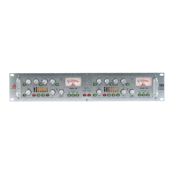
For economic reasons, these console preamps are typically of lower quality than a single, dedicated unit. You can use the dbx 586 to get your basic tracks sounding great and then you can run the finished mix through it for final “tube” treatment and equalization.The dbx 586’s preamplifier circuit is a hybrid design consisting of a high-voltage class A vacuum tube amplification stage, coupled with an ultra low noise, low distortion solid-state driver stage. - Page 5 Wa a rra a nt t y y This warranty is valid only for the original purchaser and only in the United States. We warrant dbx prod- ucts against defects in materials or workmanship for a period of two years from the date of original pur- chase for use, and agree to repair or, at our option, replace any defective item, except external power trans- formers, without charge for either parts or labor.
- Page 6 Another benefit of the dbx 586 is its high Common Mode Rejection Ratio (CMRR) with its inherent abili- ty to reject hum and Radio Frequency (RF) interference.With the published frequency range of 200kHz at +0/-3dB, as well as a specially designed hard wire bypassable EQ circuit, the 586 is equal to any challenge.
-
Page 7: Front Panel
Co o nnec c t t ing t t he 586 t t o o Yo o ur Sy y s s t t em To connect the 586 to your system, refer to the following steps: • Turn off all equipment before making any connections. •... - Page 8 NOTE:When recording in this way, the dbx PeakPlus™ limiter can be used to ensure that the level going to tape does not exceed the level set by the limiter’s Threshold control. This is especially useful for record- ing to a DAT or digital multitrack recorder where exceeding 0dB FS on the recorder can cause cata- strophic distortion.
- Page 9 MANUFACTURED UNDER THE FOLLOWING U.S. PATENTS: 4,368,425 5,282,252. OTHER PATENTS PENDING. Channel 1 Power Supply, if required Figure 2: Connecting the 586 to a recorder Op p era a t t ing Co o nt t ro o ls s FRONT PANEL PEAK PEAK...
-
Page 10: Rear Panel
¨ FREQUENCY control This control selects the center frequency for the mid frequency filter. The frequency range is 100 Hz to 8 kHz. HIGH control This control varies the gain of the high frequency equalization; the gain range is -15 to +15 dB. The high frequency filter is a shelving highpass configuration with a knee frequency of 12 kHz. - Page 11 +4 dBu/-10 dBV switch is in the -10 dBV position, 0 VU corresponds to an output level of -10 dBV. DITHER switch This switch becomes active only when the optional dbx TYPE IV™ Conversion System digital output mod- ule is installed. Refer to the manual for the TYPE IV™ Conversion System for a description of the func- tion of this switch.
- Page 12 The audio signal produced at the SEND output is taken from a point in the circuit after the dbx 586’s tube stages.You can run a cable from this jack to the input of your external processor. Inserting a jack here will not interrupt the audio output.This is to allow the SEND to be used as direct post-preamp output that bypasses the main output stage of the dbx 586.
- Page 13 RETURN Connect the output of your external processor back to the dbx 586 through this jack. An audio signal returning here is passed along to the EQ and the output stages. This input can also be used as an alternate input that makes use of the equalizer, limiter, and digital output option.
- Page 14 ¨ Sp p ec c ific c a a t t io o ns s MICROPHONE INPUTS Connectors: Female XLR Pin 2 hot Type: Electronically balanced/unbalanced Impedance: 1.70 kΩ 150 - 200 Ω Optimum Microphone Impedance: Maximum Input Level: > +13 dBu, or +33 dBu with 20 dB pad engaged CMRR: >...
-
Page 15: Specifications
Monitors the signal level at the Insert Return jack OUTPUT: Monitors the output signal level DIGITAL OUTPUT OPTION SWITCHES (Note:The digital output option switches are enabled only when the optional dbx TYPE IV™ module is installed in the unit.) DITHER: See manual for dbx Type IV™ option SHAPE: See manual for dbx Type IV™... - Page 16 ¨ A Harman International Company 8760 South Sandy Pkwy. Sandy, Utah 84070 Phone: (801) 568-7660 Fax: (801) 568-7662 IntÕl Fax: (603) 672-4246 Questions or comments? E¥mail us at: customer@dbxpro.com or visit our World Wide Web home page at: www.dbxpro.com SUP0021 2/26/98...


Need help?
Do you have a question about the 586 and is the answer not in the manual?
Questions and answers