
Related Manuals for Clarke Power IG1000


Summary of Contents for Clarke Power IG1000
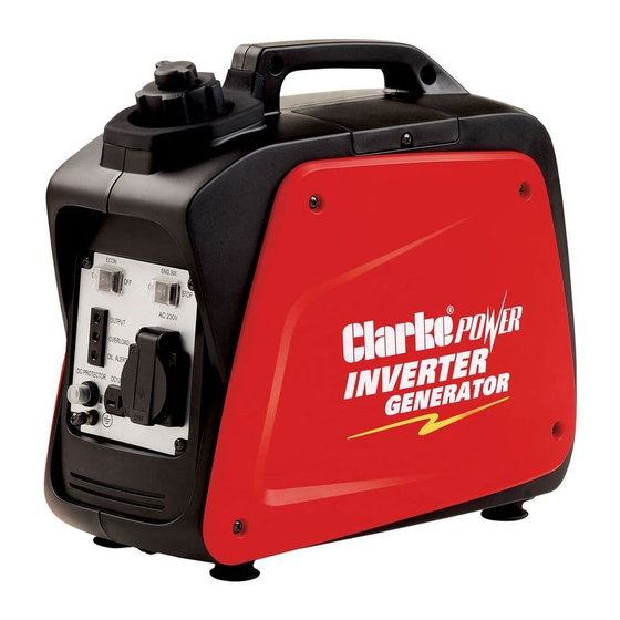
- Page 1 1KW INVERTER GENERATOR MODEL NO: IG1000 PART NO: 8877050 OPERATION & MAINTENANCE INSTRUCTIONS LS0709...
-
Page 2: Introduction
INTRODUCTION Thank you for purchasing this CLARKE 1kw Inverter Generator Before attempting to use this product, please read this manual thoroughly and follow the instructions carefully. In doing so you will ensure the safety of yourself and that of others around you, and you can look forward to your purchase giving you long and satisfactory service. -
Page 3: Table Of Contents
TABLE OF CONTENTS INTRODUCTION ............... 2 GUARANTEE ..............2 PARTS AND SERVICING ..........2 TABLE OF CONTENTS ............3 GENERAL SAFETY RULES ..........4 Work area ..................4 Positioning the generator .............. 4 Fire prevention ................4 Prevention of electric shock ............5 Additional safety rules for generators .......... -
Page 4: General Safety Rules
GENERAL SAFETY RULES WARNING: EXHAUST FUMES CAN BE EXTREMELY DANGEROUS IF INHALED WORK AREA • Always use in a well ventilated area. • Always position the exhaust outlet away from people. • Read these safety instructions before using the equipment. •... -
Page 5: Prevention Of Electric Shock
6. Never start the engine if there is spilled fuel. Any spillage must be wiped clean and the generator allowed to dry before attempting to start the engine. PREVENTION OF ELECTRIC SHOCK 1. Never use the generator in wet conditions unless it is well protected/ covered. -
Page 6: Safety Symbols
SAFETY SYMBOLS Caution - The user should be aware of a general hazard Dangerous Voltage Flammable Hot Surface - Do not touch Poisonous fumes - Do not use the generator in an enclosed space. Read Instruction manual before use. -
Page 7: Generator Overview
GENERATOR OVERVIEW DESCRIPTION NO DESCRIPTION Air Vent Knob Earthing Point Fuel Cap Economy Control Switch Fuel Valve Knob AC Socket Starting Handle DC Socket Left Side Maintenance Cover DC Circuit Breaker Top Maintenance Cover Overload Indicator Muffler Output Indicator Choke Oil Alarm Indicator Engine ON/OFF Switch... -
Page 8: Unpacking And Assembly
UNPACKING AND ASSEMBLY Unpack your Generator and check to ensure the following items are present. Should there be any deficiency or damage caused during transit contact your Clarke dealer immediately. • 1 x Inverter Generator • 1 x Spark Plug Box Spanner •... -
Page 9: Checking The Engine Oil Level
WARNING: TO CARRY OUT THIS CHECK, SWITCH THE ENGINE OFF. WARNING: TAKE CARE NOT TO TOUCH ANY HOT PARTS OF THE GENERATOR WHEN CHECKING THE OIL LEVEL. CHECKING THE ENGINE OIL LEVEL NOTE: Place the generator on a level surface and check the oil level as follows. -
Page 10: Checking The Fuel Level
CHECKING THE FUEL LEVEL Make sure there is sufficient fuel in the tank. To check the fuel level, open the Fuel filler cap fuel filler cap. 2. Slowly add fuel to the fuel tank (maximum 2.7L) • Do not overfill the fuel tank. 3. -
Page 11: Checking The Air Filter
4. Remove the air filter element. 5. Make sure that the air filter is clean and not damaged. • If the air filter is damaged contact Clarke spare parts department for a replacement See page 2 • If the filter is dirty, wash the filter in a solution of warm water and mild detergent and rinse thoroughly. -
Page 12: Using Your Generator
USING YOUR GENERATOR STARTING THE ENGINE 1. Remove all connections from the AC sockets. Hold the fuel tank cap so that it will not move, and turn the air air vent knob vent knob to the ON position. 3. Turn fuel valve to the ON position. 4. - Page 13 NOTE: When you first start the generator, the overload indicator may light up for a few seconds, this is normal. If the overload indicator is still lit after 5 seconds, stop the engine and contact your Clarke dealer. 7. Once the engine has warmed up,...
-
Page 14: Connecting Electrical Devices
CONNECTING ELECTRICAL DEVICES The generator can supply both 230V AC and 12V DC AC POWER 1. Start the engine. See page 12. 2. Make sure the appliance is turned off before connecting it to the generator. 3. Connect the appliance to the generator. - Page 15 DC POWER For charging car batteries only CAUTION: MAKE CONNECTIONS TO THE BATTERY AFTER STARTING THE ENGINE. 1. Set the economy control switch to ‘OFF’. 2. Start the generator. 3. Connect the battery charging leads to the generator. 4. Connect the battery charging leads to the battery.
-
Page 16: Economy Switch
ECONOMY SWITCH When the economy control switch is turned on, the engine speed varies according to the load connected. This results in decreased fuel consumption and less noise. When the economy control switch is turned off, the engine runs at the 5,500 r/min. -
Page 17: Shutting Down The Generator
SHUTTING DOWN THE GENERATOR To stop the generator in an emergency simply set the engine switch to ‘OFF’. NOTE: Turn off any electric devices. NOTE: Set the economy control switch to the ‘0’ (OFF) position. 1. Disconnect any electric devices. 2. -
Page 18: Maintenance
MAINTENANCE THE ENGINE OIL (EVERY 20 HOURS OF USE) CAUTION: PROLONGED EXPOSURE TO USED ENGINE OIL IS DANGEROUS, ALWAYS WASH YOUR HANDS THOROUGHLY AFTER HANDLING USED ENGINE OIL. 1. Remove the left side maintenance panel. 2. Turn the oil filler cap anti- clockwise and remove from the oil tank, wipe the dipstick with a clean cloth. -
Page 19: The Air Filter (Every 50 Hours Of Use)
3. Remove the air filter cover. 4. Remove the air filter element. 5. If the air filter is damaged contact Clarke spare parts department for a replacement See page 2. • If the filter is dirty, wash the filter in a solution of warm water and mild detergent and rinse thoroughly. -
Page 20: The Spark Plugs (Every 50 Hours Of Use)
THE SPARK PLUGS (EVERY 50 HOURS OF USE) CAUTION: ALLOW THE ENGINE TO COOL BEFORE REMOVING THE SPARK PLUG. 1. Remove the top maintenance panel. 2. Remove the spark plug cap from the spark plug. 3. Use a spark plug spanner (supplied) to remove the spark plug. -
Page 21: Fuel Tank Filter
FUEL TANK FILTER Just inside the fuel tank is a fuel filter, check this filter periodically and remove any contaminants which may have accumulated. Remove the fuel tank cap and Fuel filler cap filter. Clean the filter with solvent. If damaged, replace. -
Page 22: Troubleshooting
The air filter is dirty Clean the air filter. See page 19 difficult to start If this does not solve your problem, please contact the Clarke service department. see below. PARTS AND SERVICING For Parts & Servicing, please contact your nearest dealer, or CLARKE International, on one of the following numbers. -
Page 23: Specifications
SPECIFICATIONS IG1000 Engine Engine Model 144F Type Forced air cooled 4- stroke gasoline OHV Displacement (cm Ignition type Fuel tank capacity (L) Maximum run time (h) Engine oil capacity (L) 0.25 Guaranteed sound power (L Generator Rated Frequency (Hz) Rated AC Voltage (V) Rated Power (kVA) Max. -
Page 24: Exploded Diagram & Parts List
EXPLODED DIAGRAM & PARTS LIST... - Page 25 EXPLODED DIAGRAM & PARTS LIST DESCRIPTION PART NO DESCRIPTION PART NO Engine RKIG100001 Bakelite pad RKIG100037 Ignition coil sleeve RKIG100002 Carburetor RKIG100038 Ignition coil RKIG100003 M4 nut RKIG100039 M6 Hex bolt RKIG100004 Washer RKIG100040 Stud(short) RKIG100005 Step motor holder RKIG100041 Sensor Assembly RKIG100006 M4 hex bolt...
- Page 26 EXPLODED DIAGRAM & PARTS LIST DESCRIPTION PART NO Pads RKIG100073 M5 nut RKIG100074 M5 screw cap RKIG100075 M5 Hex bolt RKIG100076 CDI box holder RKIG100077 Vacuum pump RKIG100078 Fuel inlet hose RKIG100079 Vacuum pipe RKIG100080 Pump inlet hose RKIG100081 M5 Hex bolt RKIG100082 CDI box assembly RKIG100083...
-
Page 27: Declaration Of Conformity
The CE mark was first applied in: 2006 Product Description: 1kW Inverter Generator Model number(s): IG1000 Serial / batch Number: Current Manufacture. Date of Issue: 01/05/2008 Signed A.C. AIKEN Senior Manager Clarke International. IG1000- RV1.doc Page 1 of 1...
Need help?
Do you have a question about the Power IG1000 and is the answer not in the manual?
Questions and answers