Asus GigaX 1024P User’s User Manual
Gigax management software
Hide thumbs
Also See for GigaX 1024P User’s:
- Quick installation manual (9 pages) ,
- User manual (44 pages)
Table of Contents
Advertisement
Copyright Information
No part of this manual, including the products and software described in it, may be reproduced, transmitted,
transcribed, stored in a retrieval system, or translated into any language in any form or by any means, except
documentation kept by the purchaser for backup purposes, without the express written permission of ASUS-
TeK COMPUTER INC. ("ASUS").
ASUS PROVIDES THIS MANUAL "AS IS" WITHOUT WARRANTY OF ANY KIND, EITHER EX-
PRESS OR IMPLIED, INCLUDING BUT NOT LIMITED TO THE IMPLIED WARRANTIES OR CON-
DITIONS OF MERCHANTABILITY OR FITNESS FOR A PARTICULAR PURPOSE. IN NO EVENT
SHALL ASUS, ITS DIRECTORS, OFFICERS, EMPLOYEES OR AGENTS BE LIABLE FOR ANY IN-
DIRECT, SPECIAL, INCIDENTAL, OR CONSEQUENTIAL DAMAGES (INCLUDING DAMAGES FOR
LOSS OF PROFITS, LOSS OF BUSINESS, LOSS OF USE OR DATA, INTERRUPTION OF BUSINESS
AND THE LIKE), EVEN IF ASUS HAS BEEN ADVISED OF THE POSSIBILITY OF SUCH DAM-
AGES ARISING FROM ANY DEFECT OR ERROR IN THIS MANUAL OR PRODUCT.
Product warranty or service will not be extended if: (1) the product is repaired, modified or altered, unless
such repair, modification of alteration is authorized in writing by ASUS; or (2) the serial number of the
product is defaced or missing.
Products and corporate names appearing in this manual may or may not be registered trademarks or copy-
rights of their respective companies, and are used only for identification or explanation and to the owners'
benefit, without intent to infringe.
SPECIFICATIONS AND INFORMATION CONTAINED IN THIS MANUAL ARE FURNISHED FOR
INFORMATIONAL USE ONLY, AND ARE SUBJECT TO CHANGE AT ANY TIME WITHOUT NO-
TICE, AND SHOULD NOT BE CONSTRUED AS A COMMITMENT BY ASUS. ASUS ASSUMES NO
RESPONSIBILITY OR LIABILITY FOR ANY ERRORS OR INACCURACIES THAT MAY APPEAR
IN THIS MANUAL, INCLUDING THE PRODUCTS AND SOFTWARE DESCRIBED IN IT.
Copyright © 2004 ASUSTeK COMPUTER INC. All Rights Reserved.
Limitation of Liability
Circumstances may arise where because of a default on ASUS' part or other liability, you are entitled to
recover damages from ASUS. In each such instance, regardless of the basis on which you are entitled to
claim damages from ASUS, ASUS is liable for no more than damages for bodily injury (including death)
and damage to real property and tangible personal property; or any other actual and direct damages resulted
from omission or failure of performing legal duties under this Warranty Statement, up to the listed contract
price of each product.
ASUS will only be responsible for or indemnify you for loss, damages or claims based in contract, tort or
infringement under this Warranty Statement.
This limit also applies to ASUS' suppliers and its reseller. It is the maximum for which ASUS, its suppliers,
and your reseller are collectively responsible.
UNDER NO CIRCUMSTANCES IS ASUS LIABLE FOR ANY OF THE FOLLOWING: (1) THIRD-
PARTY CLAIMS AGAINST YOU FOR DAMAGES; (2) LOSS OF, OR DAMAGE TO, YOUR RECORDS
OR DATA; OR (3) SPECIAL, INCIDENTAL, OR INDIRECT DAMAGES OR FOR ANY ECONOMIC
CONSEQUENTIAL DAMAGES (INCLUDING LOST PROFITS OR SAVINGS), EVEN IF ASUS, ITS
SUPPLIERS OR YOUR RESELLER IS INFORMED OF THEIR POSSIBILITY.
Advertisement
Table of Contents

Related Manuals for Asus GigaX 1024P User’s


Summary of Contents for Asus GigaX 1024P User’s
-
Page 1: Copyright Information
Warranty Statement, up to the listed contract price of each product. ASUS will only be responsible for or indemnify you for loss, damages or claims based in contract, tort or infringement under this Warranty Statement. - Page 2 Centralized Network Management GigaX Management Software User’s Manual Product Name: CNM Software Manual Revision: 1 E1604 Release Date: May 2004...
-
Page 3: Table Of Contents
1 Introduction ................1-3 1.1 GigaX 1024P Features ............ 1-3 1.2 Using this Document ............1-5 1.3 ASUS contact information ..........1-5 2 Getting to Know the GigaX 1024P ........1-6 2.1 Parts List ................1-6 2.2 Front Panel ..............1-7 2.3 Rear Panel ............... -
Page 4: Introduction
1 Introduction Congratulations on your purchase of the ASUS GigaX 1024P. You can now manage your LAN (Local Area Network) through a friendly and powerful user interface, the ASUS CNM. The ASUS CNM runs on Windows OS. Please refer to the CNM installation guide for CM installation details. -
Page 5: Using This Document
1.2 Using this Document 1.2.1 Notational conventions • Acronyms are defined the first time they appear in text and in the glossary. • For brevity, the GigaX switch is referred to as the switch. • The terms LAN and network are used interchangeably to refer to a group of Ethernet-connected computers at one site. -
Page 6: Asus Contact Information
General Fax: +49-2102-959911 Technical Support Online Support: www.asuscom.de/support Support Fax: +49-2102-959911 Component Support: +49-2102-95990 Notebook Support: +49-2102-959910 ASUS COMPUTER (Middle East and North Africa) Web Site Address: www.ASUSarabia.com General Telephone: +9714-283-1774 General Fax: +9714-283-1775 GigaX Centralized Network Management User’s Manual... -
Page 7: Getting To Know The Gigax 1024P
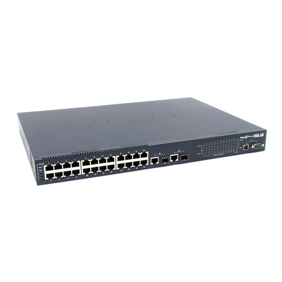
2 Getting to Know the GigaX 1024P 2.1 Parts List In addition to this document, the switch should come with the following: • GigaX 1024P managed switch • AC Power cord • Rack installation kit (2 brackets with 6 screws (M3 x 6L)) •... -
Page 8: Front Panel
2.2 Front Panel The front panel contains LED indicators that show the status of the unit. Label Color Light Function POWER Green The switch is powered on and operate normally The switch is powered off 10/100 ports from 1 to 24 STATUS / SPEED Green Ethernet link is established in 100 Mbps... -
Page 9: Technical Specifications
2.4 Technical Specifications Physical Dimensions: 43.5mm(H) X 444 mm(W) X 200mm(D) Environmental Ranges: Operating temperature: -10ºC to 50ºC (14ºF to 122ºF) Storage temperature: -40ºC to 70ºC (-40ºF to 158ºF) Operating humidity: 15% to 90% Storage humidity: 00% to 95% Power: Input: 100-240V AC / 2.5A / 50-60Hz Power Consumption:... -
Page 10: Quick Start Guide
• Part 3 shows you how to configure basic settings on the GigaX. This Quick Start Guide assumes that you have installed ASUS CNM in a Windows PC. Both the switch and the PC are located in the same network. -
Page 11: Part 2 -Start The Switch
(with CNM installed), and to the network. 3.2.1 Step 1. Connect to the PC with CNM Installed The switch can be managed through the ASUS CNM software that is running on a Windows OS computer. Please refer to the CNM installation guide for details. -
Page 12: Led Indicators
3.2.3 Step 3. Attach the power cord. 1. Plug the female end of the AC power cord to the POWER receptacle on the back of the switch. 2. Check the front LED indicators with the table 3.1. If the LEDs illuminate as expected, the switch hardware is working properly. -
Page 13: Management From Cnm
3.3 Management from CNM In Part 3, start the CNM program and manage the switch to meet your network requirements. Before starting CNM, make sure that your manage station is attached to the same network as the switch is. Otherwise, CNM will not be able to discover the switch. - Page 14 3. Select the proper NIC at the same network with the switch, then click on the Discovery icon in the tool bar. After the discovery is done, the left frame of the window will show the MAC addresses of the switches discovered by the CNM as Figure 3.3.
- Page 15 3.3.2 Password Recovery The switch is protected by a password. The password is required to make CNM able to manage the switch. Once the password is lost, you need to reset the password back to factory default password, which is 0x2379. The password is four digit long, could be change through CNM.
-
Page 16: Management Functions
4 Management Functions ASUS provide a Centralized Network Management (CNM) software to allow users manage the switch in your network. The program is designed to work best with Microsoft Windows operation system. 4.1 Start CNM Program 1. Install CNM in a computer running Windows OS. Refer to CNM installation guide for detail installation steps. -
Page 17: Functional Layout
4.2 Functional Layout The CNM window consists of three separate frames. The top frame has switch logo and front panel as shown in Figure4.2. This frame remains on the top of the browser window all the times and updates the LED status periodically. - Page 18 Click on the NIC, it shows the topology of the switches in the network. If multiple switches are cascaded, the tree view will show the relationship of those switches as Figure 4.4. Figure 4.4. Tree view of the network topology The right frame displays the specified switch configurations or graphics for the statistics.
-
Page 19: General Settings For Cnm
4.3 General Settings for CNM There are menu bar and tool bar on the top of the CNM window. They offer general settings for CNM. The Topology item provides the general network discovery, manually add or delete switches, and load or save the current discovered topology. The Setup item provides the update interval and password settings. - Page 20 5. Add Switch: add a switch to the topology tree manually. A window pops out for this purpose as Figure 4.6. Select the network adapter you want the switch to attach to, give the switch MAC and name, and an authentication key as the password if you don’t use the default one (2379), then click OK to finish the action.
- Page 21 7. Load: load a topology list from a file. There is a tool bar button for it. 8. Save Topology: save the current topology list to a file. There is a tool bar button for it. 9. Save As: specify a file name to save the topology list 10.
-
Page 22: Switch Topology
4.4 Switch Topology The switch topology frame is on the left part of the CNM window. It shows the discovered switches and the relationship among them. Each presents a NIC interface. The interface name and MAC address is shown after the. The switch topology shows the relationship among the switches in a tree view. - Page 23 4.4.2 Switch Add and Removal Discovery action will create the topology tree by all the discovered switches. The default password will be used in the discovery process. Sometimes you may have a switch with another password that is different from the default one.
- Page 24 Once a switch is added to the topology tree, you can find it in the corresponding place. You have to left click the switch symbol to switch the current status/configuration window from other switch to this switch. If the communication is good, you can see the linking status window on the right frame of the CNM window, and the topology tree will display the switch symbol in a correct place to show the relationship.
-
Page 25: Switch Setup
4.5 Switch Setup Before using the configuration windows, it is better to know following buttons or icons because they are used throughout the setup. The following table describes the function for each button or icon. Table 4.1 2. Description of Commonly Used Buttons and Icons Button/Icon Function Apply to the selected switch... -
Page 26: System
4.6 System There are reboot, link status and change password under the system menu. 4.6.1 Reboot The 1024P provides hardware and software reset as shown in figure 4.13. Hardware reset is to reset the system at a initial state like the process of power on hardware reset. - Page 27 4.6.2 Link Status Link status table shows the port information including speed, duplex mode and flow control. Click on the Reload button will get the update information. Figure 4.14 shows the status table. Figure 4.14. Link Status GigaX Centralized Network Management User’s Manual...
- Page 28 4.6.3 Change Password A valid password consists of 4 digits, from 0 to 9, and a to f. The authenticator does not check upper case or lower case. For example, password “12ab” is treated as “12AB”. Once the password gets changed, CNM will use the password to retrieve the information about the switch.
- Page 29 4.6.4 Load You can load configuration from the switch or the local file as shown in Figure 4.15. This action will update the current configuration in the CNM. If you want to keep the current configuration, please refer to section 4.6.5. Figure 4.15.
- Page 30 4.6.5 Save Save all the configurations to a local file for future reference. Once you create a configuration file in CNM, you can use it to apply to the other switches to save your time. It is also a backup file for configuration. It is recommended to have a good file name to identify that the configuration is for the certain switch(es).
- Page 31 4.6.6 Apply and Save It applies all the current settings in CNM to the switch and save them in the switch permanently. It is recommended to back up the existed switch configurations before applying a new configuration to the switch. Figure 4.17.
-
Page 32: Configuration
4.7 Configuration The Configuration menu provides the configuration for all the functions that the switch can supports, like physical interface, link aggregation, bandwidth control, traffic control, VLAN, IGMP snooping and QoS. To keep all the new configurations and save the bandwidth for communications, each configuration page will not retrieve information from switch until you click the Reload button. - Page 33 1. Enable or disable a port 2. Speed and duplex mode. Select 1000 full-duplex on the Fast Ethernet ports (from 1 to 24) will set the ports to 100 full-duplex mode. 3. Flow control - Back pressure flow control is used in half and full duplex modes to prevent packet loss.
- Page 34 Link aggregation creates new virtual links with more bandwidth. For example, port 1 and 2 can work together as one link to another device. The new virtual link has 200Mbps bandwidth. The switch provides 8 groups of link aggregations shown on the top of figure 4.19. Click on the Reload button to retrieve the configuration from switch.
- Page 35 4.7.4 Traffic Control Traffic control is to set the following items 1. Broadcast storm filtering control: if enabled, each port start to drop broadcast packets after a continuous received broadcast packets count up to 64. It will be back to normal if no more broadcast packet is received in 800ms or any non-broadcast packet is received.
- Page 36 Figure 4.21. VLAN All VLAN behavior will be influenced by VLAN control option. Click Control Option and a window will pop out as Figure 4.22. Enable or disable these options carefully, these options are global setting for VLAN Figure 4.22. VLAN Control Options GigaX Centralized Network Management User’s Manual...
- Page 37 7. VLAN function: enable or disable the VLAN function. 8. Unicast packet inter-VLAN leaky: to enable the packet to be forwarded to a destination port (L2 table hit) at different VLAN. 9. ARP broadcast packet inter-VLAN leaky: to enable ARP frame to broadcast to all switch ports.
- Page 38 4.7.7 QoS Setup The system support 2 level priority queues. The queue service rate is based on the packet-based Weighted Round Robin algorithm. The ratio can be set as 4:1, 8:1, 16:1, or strictly high priority first. The port-based priority is to decide the packet priority by the receiving ports. You can select the high priority ports from the switch graphic.
-
Page 39: Statistics
4.8 Statistics Statistics offer Port Traffic, Traffic History and Comparison charts. The switch has 3 counters for 8 kinds of statistics. So you cannot see all the statistics at the same time. That is, the old statistics data will be gone if you start to use the counter for another statistics. - Page 40 4.8.2 Traffic History Select the statistics item, ports and colors you want to see in the chart, then press the Draw Traffic Chart button to start the drawing. The chart will be auto updated in the time interval you set in Setup menu. Refer to 4.3.2 for time interval setup.
- Page 41 4.8.3 Comparison Select the statistics item to do comparison for port 1 to 26. Press the Draw Traffic Chart button to start the drawing. The chart will be auto updated in the time interval you set in Setup menu. Figure 4.27. Port Comparison GigaX Centralized Network Management User’s Manual...
Need help?
Do you have a question about the GigaX 1024P User’s and is the answer not in the manual?
Questions and answers