Aprilaire 1700 Safety And Installation Instructions Manual
Hide thumbs
Also See for 1700:
- Safety and installation instructions manual (16 pages) ,
- Owner's manual (4 pages) ,
- Installation manual (4 pages)
Table of Contents
Advertisement
Filter
Access
Wiring
Access
Safety and Installation Instructions
INSTALLER - PLEASE NOTE!
1. Installation must conform to all applicable codes.
2. A dedicated 15 Amp circuit is required for proper
operation of the dehumidifier. If a dedicated circuit
is not available, do not install unit.
TABLE OF CONTENTS
Safety Instructions . . . . . . . . . . . . . . .2
Overview . . . . . . . . . . . . . . . . . . . . . . .2
Specifications . . . . . . . . . . . . . . . . . . .2
Location Notes . . . . . . . . . . . . . . . . . .2
Ducting . . . . . . . . . . . . . . . . . . . . . . . .3
Drain Line . . . . . . . . . . . . . . . . . . . . . .3
Hanging . . . . . . . . . . . . . . . . . . . . . . .3
Humidity
Control
Inlet
Wire
Routing
Port
Model 1700
Installations
Whole House . . . . . . . . . . . . . . . . . . .4
Localized . . . . . . . . . . . . . . . . . . . . . . .6
Convertible . . . . . . . . . . . . . . . . . . . . .8
Ventilation and Fan Cycling . . . . . . .10
Sales: 800-934-9194
Filter
Access
3. For protection of the compressor, unit must be
transported and installed in an upright position.
If the unit was shipped or stored on its side, a 24 hour
settling period is required before running the unit.
Float Switch . . . . . . . . . . . . . . . . . . .12
Dip Switch Definitions . . . . . . . . . . .12
System Checkout . . . . . . . . . . . . . . .13
Troubleshooting . . . . . . . . . . . . . . . .14
Sequences
of Operations . . . . . . . . . . .Back Cover
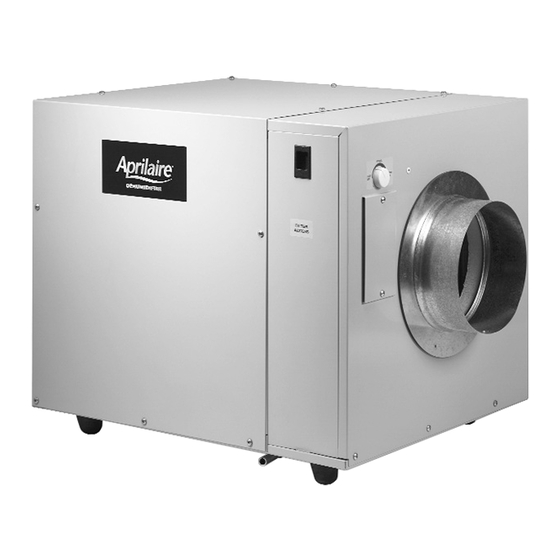
Dehumidifier
Service
Access
Outlet
Port
Drain
On/Off
Switch
Advertisement
Table of Contents

Related Manuals for Aprilaire 1700


Summary of Contents for Aprilaire 1700
-
Page 1: Table Of Contents
Dehumidifier Sales: 800-934-9194 Service Filter Humidity Filter Access Access Control Inlet Access Outlet Port Drain Wiring Wire On/Off Access Routing Switch Port Safety and Installation Instructions Model 1700 INSTALLER – PLEASE NOTE! 1. Installation must conform to all applicable codes. 3. -
Page 2: Safety Instructions
OVERVIEW The purpose of the Aprilaire Dehumidifier is to keep the humidity in the house at acceptable limits to reduce the unwanted effects of high humidity. The dehumidifier will measure the dewpoint of the house to decide if it needs to run. The dryness set point can be adjusted with the control knob on the inlet side of the unit. -
Page 3: Ducting
DUCTING The Aprilaire Dehumidifier is supplied with two • For optimal moisture removal, airflow should be at or above 8” round collars. These are packaged with a 275 CFM. condensate trap inside the unit behind the filter • The total static pressure across the dehumidifier must not access panel. -
Page 4: Whole House
WHOLE HOUSE INSTALLATION AND OPERATION In this configuration the dehumidifier will pull air from the return duct. The air passes through the dehumidifier, where moisture is removed, and then returned to the HVAC system downstream of the cooling coil in the supply plenum. This installation is used when the HVAC unit conditions the area where dehumidification is needed. - Page 5 WHOLE HOUSE INSTALLATION AND OPERATION (CONTINUED) DEHUMIDIFIER N.C. BACKFLOW FIGURE 4 – WIRING 24 VAC CONTROL DAMPER (10 VA min) TRANSFORMER THERMOSTAT HVAC EQUIPMENT See page 10 for ventilation control wiring instructions. See page 10 for fan cycling wiring instructions. See page 12 for float switch wiring instructions.
-
Page 6: Localized
LOCALIZED INSTALLATION AND OPERATION In this configuration the dehumidifier will pull air from an area in the home. The air passes through the dehumidifier, where moisture is removed, and then is returned to the area. This installation is used when the HVAC unit conditions an area other than where dehumidification is needed. - Page 7 LOCALIZED INSTALLATION AND OPERATION (CONTINUED) DEHUMIDIFIER FIGURE 7 – WIRING CONTROL THERMOSTAT HVAC EQUIPMENT See page 10 for ventilation control wiring instructions. See page 10 for fan cycling wiring instructions. See page 12 for float switch wiring instructions. 90-964 FIGURE 8 – SETTINGS SYSTEM SETUP Standard Fan Cycling...
-
Page 8: Whole House / Localized Convertible
WHOLE HOUSE / LOCALIZED CONVERTIBLE INSTALLATION AND OPERATION In this configuration the dehumidifier will automatically switch between whole-house dehumidification when the HVAC equipment is on, and localized dehumidification when the equipment is off. This installation is used to dehumidify a whole house and a separate unconditioned space like an unfinished basement, or an area where circulation from that location throughout the entire house is undesirable. - Page 9 WHOLE HOUSE / LOCALIZED CONVERTIBLE INSTALLATION AND OPERATION (CONTINUED) DEHUMIDIFIER FIGURE 10 – WIRING 24 VAC CONTROL DEHUMIDIFIER SYSTEM DAMPERS (40 VA min) TRANSFORMER THERMOSTAT HVAC EQUIPMENT WIRE NUT See page 10 for ventilation control wiring instructions. See page 10 for fan cycling wiring instructions. See page 12 for float switch wiring instructions.
-
Page 10: Ventilation And Fan Cycling
VENTILATION / FAN CYCLING SETTINGS The Aprilaire Dehumidifier has the option OPTIONAL to monitor HVAC heating, cooling and fan FIGURE 12 DEHUMIDIFIER VENTILATION 24 VAC calls to assure the HVAC fan has CONTROL DAMPER (10 VA min) operated a predetermined amount of TRANSFORMER time each 1/2, 1, 2 or 3 hours. - Page 11 SENSOR Note: The dehumidifier can control the HVAC fan to provide fan cycling, regardless of whether or not an outdoor SENSOR ventilation duct is installed. SENSOR • An Aprilaire ® Normally-Closed Damper (Model 6506) should BRACKET OUTDOOR ABOVE EXPECTED TEMPERATURE SENSOR be installed in the outside air intake.
-
Page 12: Float Switch
FLOAT SWITCH If the Model 1700 is installed in an attic, the unit should be FIGURE 18 placed in a drain pan with a normally closed condensate overflow safety switch (also known as a float switch). The float switch should be wired to the float switch terminals on the dehumidifier LOW VOLTAGE NORMALLY control board. -
Page 13: System Checkout
30 seconds. After 1 minute the dehumidifier blower and compressor will shut off (“TEST” mode only). 4. If the dehumidifier blower does not activate in TEST mode, refer to the Troubleshooting Guide. 5. For ventilation (optional) test, be sure that 24 VAC is applied in series with the Aprilaire ®... -
Page 14: Troubleshooting
TROUBLESHOOTING GUIDE SYMPTOM TROUBLESHOOTING PROCEDURE / POSSIBLE REASON Dehumidifier is producing • Reheat of outgoing air will cause a temperature increase across the dehumidifier. hot air. • Unit will possibly run continuously initially. After unit has “dried” home, dehumidifier will cycle, reducing load. Dehumidifier Blower is running, •... - Page 15 TROUBLESHOOTING GUIDE (CONTINUED) SYMPTOM TROUBLESHOOTING PROCEDURE / POSSIBLE REASON The ventilation damper • The damper will not open if the cycle time within the current period has already does not open when the been met. For instance if the cycle time is set to 5 minutes and the control has HVAC fan is active.
-
Page 16: Dehumidifier/Damper/Ventilation Sequence Of Operation
DEHUMIDIFIER SEQUENCE OF OPERATION IF THE DEHUMIDIFIER IS NOT WIRED TO THE HVAC EQUIPMENT, THE DEHUMIDIFIER WILL SAMPLE AT THE END OF THE CYCLE PERIOD. With 3 minutes left in the Cycle Period, the dehumidifier will turn on the dehumidifier blower for 2 minutes. During this time the temperature and relative humidity are measured and the dewpoint is calculated.
Need help?
Do you have a question about the 1700 and is the answer not in the manual?
Questions and answers