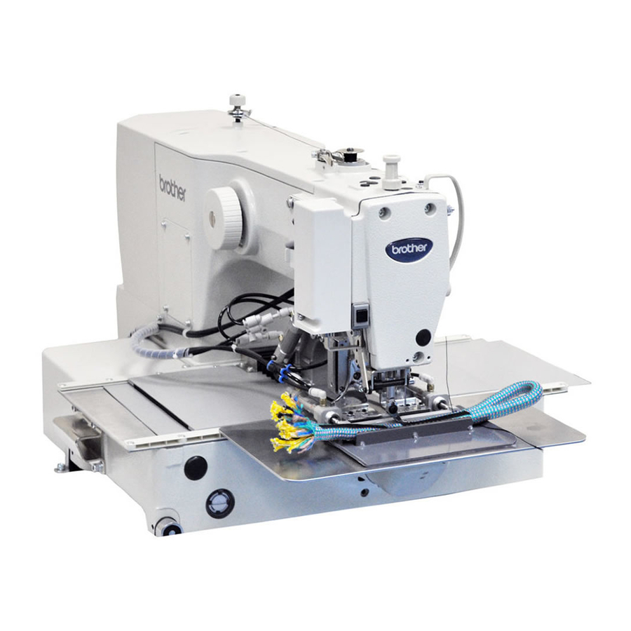
Brother BAS-300G-484/484SF Instruction Manual
Direct drive programmable electronic pattern sewer
Hide thumbs
Also See for BAS-300G-484/484SF:
- Instruction manual (88 pages) ,
- Manual de instrucciones (88 pages) ,
- Parts manual (80 pages)
Table of Contents
Advertisement
Quick Links
Download this manual
See also:
Instruction Manual
BAS-300G-484
BAS-300G-484 SF
DIRECT DRIVE
PROGRAMMABLE ELECTRONIC PATTERN SEWER
<TREBLE HOOK>
Please read this manual before using the machine.
Please keep this manual within easy reach for quick reference.
Basic Operation Manual
This
basic
operation
operations including sewing machine operations.
For cleaning, standard adjustments and more details,
please refer to the instruction manual contained in
the Document CD.
manual
describes
basic
Advertisement
Table of Contents

Related Manuals for Brother BAS-300G-484/484SF


Summary of Contents for Brother BAS-300G-484/484SF
- Page 1 Basic Operation Manual BAS-300G-484 BAS-300G-484 SF DIRECT DRIVE PROGRAMMABLE ELECTRONIC PATTERN SEWER <TREBLE HOOK> Please read this manual before using the machine. Please keep this manual within easy reach for quick reference. This basic operation manual describes basic operations including sewing machine operations. For cleaning, standard adjustments and more details, please refer to the instruction manual contained in the Document CD.
- Page 2 Thank you very much for buying a BROTHER sewing machine. Before using your new machine, please read the safety instructions below and the explanations given in the instruction manual. With industrial sewing machines, it is normal to carry out work while positioned directly in front of moving parts such as the needle and thread take-up lever, and consequently there is always a danger of injury that can be caused by these parts.
-
Page 3: Safety Instructions
SAFETY INSTRUCTIONS [1] Safety indications and their meanings This instruction manual and the indications and symbols that are used on the machine itself are provided in order to ensure safe operation of this machine and to prevent accidents and injury to yourself or other people. The meanings of these indications and symbols are given below. - Page 4 [2] Notes on safety DANGER Wait at least 5 minutes after turning off the power switch and disconnecting the power cord from the wall outlet before opening the control box cover. Touching areas where high voltages are present will result in serious injury from electric shocks.
-
Page 5: Maintenance And Inspection
CAUTION Sewing This sewing machine should only be used by If using a work table which has casters, the casters operators who have received the necessary training should be secured in such a way so that they cannot in safe use beforehand. move. - Page 6 [3] Warning labels The following warning labels appear on the sewing machine. Please follow the instructions on the labels at all times when using the machine. If the labels have been removed or are difficult to read, please contact your nearest Brother dealer. *Safety devices Devices such as eye guard, finger guard, thread take-up cover, motor...
- Page 7 Motor cover Tension release solenoid cover Solenoid cover Inner cover L Outer cover Fixed cover L Motor cover L Thread take-up cover Inner cover R Outer cover Fixed cover R Eye guard Motor cover R Finger guard Hook cover Gas spring support cover 4630M 4631M BAS-300G-484, BAS-300G-484 SF...
-
Page 8: Table Of Contents
CONTENTS 1. NAMES OF MAJOR PARTS ....5. USING THE OPERATION PANEL (BASIC OPERATIONS) ....2. USEFUL FUNCTIONS FOR 5-1. Name and function of each operation OPTIMUM SEWING......panel item ............25 3. INSTALLATION ........5-2. Loading sewing data......... 27 3-1. -
Page 9: Names Of Major Parts
1. NAMES OF MAJOR PARTS 1. NAMES OF MAJOR PARTS <BAS-300G-484 SF> <BAS-300G-484> 4632M Safety devices: (1) Power switch (2) Control box (12) Finger guard (3) CF slot (13) Eye guard (4) Operation panel (14) Thread take-up cover (5) Work clamp switch (15) Motor cover (6) Start switch (16) Solenoid cover... -
Page 10: Useful Functions For Optimum Sewing
2. USEFUL FUNCTIONS FOR OPTIMUM SEWING 2. USEFUL FUNCTIONS FOR OPTIMUM SEWING Easy threading in threading mode Page 20 When using threading mode for threading, the tension discs will open so that the thread can be threaded more easily. Furthermore, threading mode is safe because the sewing machine will not start even when the foot switch is depressed. -
Page 11: Installation
3. INSTALLATION 3. INSTALLATION CAUTION Machine installation should only be carried out by a All cords should be secured at least 25 mm away from qualified technician. any moving parts. Furthermore, do not excessively bend the cords or secure them too firmly staples, Contact your Brother dealer or a qualified electrician otherwise there is the danger that fire or electric for any electrical work that may need to be done. -
Page 12: Installing The Control Box
3. INSTALLATION 3-2. Installing the control box Remove the eight screws (1), and then remove the control box cover (2). (3) Control box (4) Bolts [4 pcs.] (5) Plain washers [4 pcs.] (6) Spring washers [4 pcs.] (7) Nuts [8 pcs.] 1840B (8) Power switch (9) Wood screws [2 pcs.]... -
Page 13: Installing The Machine Head
3. INSTALLATION 3-4. Installing the machine head (1) Pins [2 pcs.] (2) Set screws [2 pcs.] (3) Hinge rubber assemblies [2 pcs.] Place the machine head gently on top of the oil pan and the rubber cushions. NOTE: Pulse motor •... - Page 14 3. INSTALLATION (10) Auxiliary plate (11) Bolts with washer [4 pcs.] Loosen the four bolts with washer (11), Needle plate and adjust so that the auxiliary plate (10) is 0 to 0.5 mm above the needle plate. NOTE: Install the auxiliary plate (10) so that it is horizontal.
- Page 15 3. INSTALLATION (12) Gas spring holders [2 pcs.] (13) Spacer (14) Bolt (15) Nut (16) Gas spring (17) Shaft collars [2 pcs.] (18) Gas spring shaft D Be sure to install so (19) Plain washers [2 pcs.] that the side with “UP” on it is facing upward.
- Page 16 3. INSTALLATION Oil pan 4641M • Gently return the machine head to its original position. • Loosen the screw (30). Move the machine head switch (31) to the position shown in the illustration, and then secure the machine head switch (31) with the screw (30) and the accessory M3x16 screw (32). •...
-
Page 17: Tilting The Sewing Machine Head
3. INSTALLATION 3-5. Tilting the sewing machine head <CAUTION> 4642M 4643M 1. Move the presser arm assembly (1) as far as it will go in the direction of the arrow in the illustration (to the right when looking from the front of the sewing machine). 2. -
Page 18: Installing The Pneumatic Unit
3. INSTALLATION 3-7. Installing the pneumatic unit 1. Install the pneumatic unit underneath the work table. (1) Solenoid valve assembly (2) Washers [2 pcs.] (3) Wood screws [2 pcs.] (4) Rubber hose NOTE: Make sure that the pneumatic unit does not touch the control box or the work table leg. -
Page 19: Adjusting The Speed Controller
3. INSTALLATION 3-8. Adjusting the speed controller <Adjusting the lifting and lowering speeds for the work clamp> You can adjust the lifting and lowering speeds for the work clamps using the knobs (1) and (2) on valves 1 and 2. Valve 1 adjusts the right work clamp (3), and valve 2 adjusts the left work clamp (4). -
Page 20: Connecting The Cords
3. INSTALLATION 3-9. Connecting the cords 1. Gently tilt back the machine head. 2. Pass the cord bundle through the hole in the work table. 3. Loosen the two screws (1), and then open the cord presser plate (2) in the direction of the arrow and pass the cord bundle through the opening together with the following cords. - Page 21 3. INSTALLATION <Power supply motor P.C. board> <Removing> Press the tab. <Securing> <PMD P.C. board> NOTE: Route the X, Y and work clamp pulse motor harnesses so that they do not touch the PMD P.C. Be sure to make the ground connection. (Refer to "3-10.
-
Page 22: Connecting The Ground Wire
3. INSTALLATION 5. Close the cord presser plate (2) in the direction of the left arrow, and secure it by tightening the two screws (1). NOTE: Close the cord presser plate (2) securely so that no foreign objects, insects or small animals can get inside the control box. -
Page 23: Connecting The Power Cord
3. INSTALLATION 3-11. Connecting the power cord 1. Attach an appropriate plug to the power cord (1). (The green and yellow wire is the ground wire.) 2. Insert plug into properly-grounded AC power supply. * The inside of the control box uses single-phase power. -
Page 24: Installing The Eye Guard
3. INSTALLATION 3-13. Installing the eye guard CAUTION Attach all safety devices before using the sewing machine. If the machine is used without these devices attached, injury may result. (1) Screw (loosen) (2) Eye guard (tilt forward) (3) Eye guard assembly (4) Plain washers [2 pcs.] (5) Screws [2 pcs.] After installing the eye guard assembly... -
Page 25: Installing The Motor Cover
3. INSTALLATION 3-14. Installing the motor cover (1) Motor cover R 4653M (2) Screws [4 pcs.] (3) Motor cover L (4) Screws [4 pcs.] (5) Motor cover (6) Screws [2 pcs.] (7) Solenoid cover (8) Screws [2 pcs.] (9) Screws [2 pcs.] NOTE: Be careful not to clamp the cords when installing the motor cover and the... -
Page 26: Lubrication
3. INSTALLATION 3-15. Lubrication CAUTION Do not connect the power cord until lubrication is complete. If the foot switch is depressed by mistake, the sewing machine might start operating and injury could result. Be sure to wear protective goggles and gloves when handling the lubricating oil and grease, so that they do not get into your eyes or onto your skin. -
Page 27: Preparation Before Sewing
4. PREPARATION BEFORE SEWING 4. PREPARATION BEFORE SEWING 4-1. Installing the needle CAUTION Turn off the power switch before installing the needle. If the foot switch is depressed by mistake, the sewing machine might start operating and injury could result. 1. -
Page 28: Foot Switch Operating Method
4. PREPARATION BEFORE SEWING <Threading mode> Threading mode is safe because the sewing machine will not start even when the foot switch is depressed. Turn on the power switch. 4421Q Press the THREAD/CLAMP key. All indicators switch off • The work clamp (and the intermittent presser foot*) will be lowered. -
Page 29: Winding The Lower Thread
4. PREPARATION BEFORE SEWING 4-4. Winding the lower thread CAUTION Do not touch any of the moving parts or press any objects against the machine while winding the lower thread. Injury or damage to the sewing machine may result. 1. Place the bobbin onto the bobbin winder shaft (1). 4662M 2. -
Page 30: Installing The Bobbin Case
4. PREPARATION BEFORE SEWING 4-5. Installing the bobbin case CAUTION Turn off the power switch before installing the bobbin case. If the foot switch is depressed by mistake, the sewing machine might start operating and injury could result. 4664M 4665M Pull 3230Q 1. -
Page 31: Thread Tension
4. PREPARATION BEFORE SEWING 4-7. Thread tension [Thread tension reference] Upper thread #4 or similar Lower thread #4 or similar 3.0 − 3.5 Upper thread tension (N) 1.2 − 1.5 Lower thread tension (N) 0.3 − 0.6 Pre-tension (N) Needle DP x 17 #25 Normal sewing speed 1,300 sti/min... -
Page 32: Home Position Detection
4. PREPARATION BEFORE SEWING 4-8. Home position detection Before starting home position detection, check that the 4667M needle bar is at its highest position. Turn the pulley (1) in the direction of the arrow until the ridge at the bottom of the thread take-up (2) is aligned with mark on the arm. -
Page 33: Using The Operation Panel
5. USING THE OPERATION PANEL (BASIC OPERATIONS) 5. USING THE OPERATION PANEL (BASIC OPERATIONS) 5-1. Name and function of each operation panel item 4435Q (1) Power indicator Illuminates when the power is turned on. (2) CAUTION indicator Illuminates when an error occurs. (3) RESET key Used to reset errors. - Page 34 5. USING THE OPERATION PANEL (BASIC OPERATIONS) 4435Q (12) SPEED indicator Illuminates when the SELECT key (15) is pressed to shown the sewing speed setting. (13) COUNTER indicator Illuminates when the SELECT key (15) is pressed to shown the lower thread or production counter setting. (14) SPLIT No.
-
Page 35: Loading Sewing Data
5. USING THE OPERATION PANEL (BASIC OPERATIONS) 5-2. Loading sewing data Refer to "5-8. Notes on handling CF cards (sold separately)" for details on using CF cards. With the power turned off, insert the CF card into the CF slot. NOTE: •... -
Page 36: Setting The X-Scale And Y-Scale
5. USING THE OPERATION PANEL (BASIC OPERATIONS) 5-4. Setting the X-scale and Y-scale The scales are set to 100 (%) at the time of shipment from the factory. 1. Press the SELECT key (1) so that the X-SCALE indicator (2) (for X-scale setting) or the Y-SCALE indicator (3) (for Y-scale setting) is illuminated. -
Page 37: Checking The Sewing Pattern
5. USING THE OPERATION PANEL (BASIC OPERATIONS) 5-6. Checking the sewing pattern Use test feed mode to check the needle movement with only the feed mechanism operating. Check that the needle hole does not come out from the frame of the work clamp. Press the TEST key. -
Page 38: Setting The Height Of The Intermittent Presser Foot (-484 Sf Specifications Only)
5. USING THE OPERATION PANEL (BASIC OPERATIONS) 5-7. Setting the height of the intermittent presser foot (-484 SF specifications only) You can use the operation panel to change the setting value for the intermittent presser foot height. Press the THREAD/CLAMP key. All indicators switch off The sewing machine will switch to threading mode. -
Page 39: Notes On Handling Cf Cards (Sold Separately)
5. USING THE OPERATION PANEL (BASIC OPERATIONS) 5-8. Notes on handling CF cards (sold separately) • Use a CF card with a memory capacity of 32, 64, 128, 256, 512 MB, 1GB or 2GB. (CF cards with a capacity of more than 2GB are not supported.) •... -
Page 40: Sewing
6. SEWING 6. SEWING WARNING Do not allow any liquids to get onto this sewing machine, otherwise fire, electric shocks or operating problems may occur. If any liquid gets inside the sewing machine (machine head or control box), immediately turn off the power and disconnect the power plug from the electrical outlet, and then contact the place of purchase or a qualified technician. -
Page 41: Using The Stop Switch
6. SEWING 6-2. Using the STOP switch If you press the STOP switch (1) while sewing or test feeding is in progress, the CAUTION indicator (2) will illuminate and the sewing machine will stop immediately. 2264B <Clearing> 1. Press the RESET key (3). •... -
Page 42: Document Cd
Document CD For cleaning, standard adjustments and more details, please refer to the instruction manual contained in the Document CD. 3168M Contents of the Document CD The following documents are contained in PDF format. Basic Operation Manual ・ Instruction Manual ・...
Need help?
Do you have a question about the BAS-300G-484/484SF and is the answer not in the manual?
Questions and answers