Table of Contents
Advertisement
Advertisement
Table of Contents

Related Manuals for Acer Aspire XC600


Summary of Contents for Acer Aspire XC600
- Page 1 Aspire XC600 Desktop Computer Service Guide SG V1.00 PRINTED IN TAIWAN...
-
Page 2: Revision History
Revision History Please refer to the table below for the updates made on this service guide. Date Version Chapter Updates 08-17-2012 First Draft 08-22-2012 V1.00... - Page 3 Copyright Copyright © 2012 by Acer Incorporated. All rights reserved. No part of this publication may be reproduced, transmitted, transcribed, stored in a retrieval system, or translated into any language or computer language, in any form or by any means, electronic, mechanical, magnetic, optical, chemical, manual or otherwise, without...
- Page 4 Any Acer Incorporated software described in this manual is sold or licensed "as is". Should the programs prove defective following their purchase, the buyer (and not Acer Incorporated, its distributor, or its dealer) assumes the entire cost of all necessary servicing, repair, and any incidental or consequential damages resulting from any defect in the software.
- Page 5 Conventions The following conventions are used in this manual: SCREEN Denotes actual messages that appear on screen. MESSAGES NOTE Gives additional information related to the current topic. WARNING Alerts you to any physical risk or system damage that might result from doing or not doing specific actions.
-
Page 6: Fru Information
Service Guide. For ACER-AUTHORIZED SERVICE PROVIDERS, your Acer office may have a DIFFERENT part number code to those given in the FRU list of this printed Service Guide. You MUST use the list provided by your regional Acer office to order FRU parts for repair and service of customer machines. -
Page 7: Table Of Contents
Table of Contents Features and Specifications................1 System Features ............1 Audio . - Page 8 Aspire XC600 FRU List ........
-
Page 9: Features And Specifications
Chapter 1 Features and Specifications This chapter lists the features and specifications of the Aspire XC600 computer. NOTE The items listed in this section are for reference only. The exact configuration of your PC depends on the model purchased. Refer to the FRU list chapter on page 85 for a detailed list of models supported by each hardware component. -
Page 10: Audio
– PS/2 keyboard port – PS/2 mouse port port – External display (VGA) port – HDMI port – USB 2.0 ports (four) – USB 3.0 ports (two) – Ethernet jack (RJ45) – Microphone, line-out, and line-in jacks Aspire XC600 Service Guide... -
Page 11: Physical Specifications
5.808 Kg. Mainboard form factor microATX (µATX) Mainboard dimensions (W × H) 200mm*244mm , 4 Layers Environmental Requirements Aspect Description Operating temperature 5 to 35 °C (41 to 95 °F) Operating humidity 15% to 80% RH non-condensing Aspire XC600 Service Guide... -
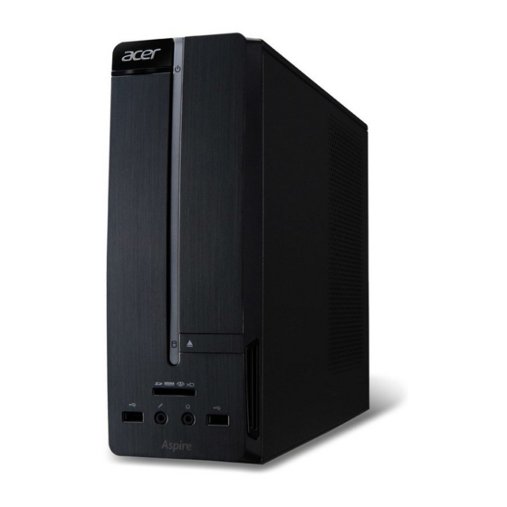
Page 12: System Tour
Multi-in-1 optional card reader supporting Memory Stick (MS), xD-Picture Card (xD), Secure Digital (SD), MultiMediaCard (MMC), Reduced-Size MultiMediaCard (RS- MMC), CompactFlash (CF) Types I and II, and Memory Stick PRO (MS PRO) Headphone jack Microphone-in jack USB 2.0 ports ODD LED indicator Power button/indicator Acer logo Aspire XC600 Service Guide... -
Page 13: Rear Panel
Rear Panel Component PCI Expansion slot Microphone jack USB 2.0 ports USB 3.0 ports HDMI port PS/2 mouse connector PS/2 keyboard connector Power connector Kensington lock External monitor port LAN connector Line-in jack Line-out jack HDMI port Aspire XC600 Service Guide... - Page 14 Aspire XC600 Service Guide...
-
Page 15: System Utilities
(BT1) may be defective. In this case, the system cannot retain configuration values in CMOS. Replace the RTC battery with a new one. NOTE For ease of reading, CMOS Setup Utility will be simply referred to as “Setup” or “Setup Utility” in this Service Guide. Aspire XC600 Service Guide... -
Page 16: Accessing The Setup Utility
Some options (marked with a ) lead to submenus that enable you to change the values for the option. Use the Up/Down/Left/Right arrow keys to scroll through the items in the submenu Aspire XC600 Service Guide... -
Page 17: Navigating Through The Setup Utility
• On one of the primary menu screens, the Exit menu displays. • On a submenu screen, the previous screen displays. • When you are making selections from a pop-up menu, closes the pop-up without making a selection. Aspire XC600 Service Guide... -
Page 18: Setup Utility Menus
Size of system memory detected during boot-up Product Name Official model name of the computer. System Serial Number System serial number. Asset Tag Number System asset tag number System Date Sets the system date. System Time Sets the system time. Aspire XC600 Service Guide... -
Page 19: Advanced Menu
Access this submenu to enable or disable operation modes for the onboard I/O controllers. PC Health Status Access this submenu to view current level of system/processor/PCH temperature, voltages, and fan speed. Smart Fan Configuration Access this submenu to view current smart fan configuration setting. Aspire XC600 Service Guide... - Page 20 If you set this item to On, the keyboard Num Lock key will be active Lock when the computer boots up. USB Beep Select whether to allow the BIOS to emit error beeps or display error Enabled Message messages during USB device enumeration. Disabled Aspire XC600 Service Guide...
-
Page 21: Advanced Chipset Configuration Submenu
Select whether to enable the Intel Virtualization Technology. VT allows a Enabled single platform to run multiple operating systems in independent Disabled partitions. Primary Video Select the graphics card adapter used at startup. Auto PCIE Onboard Aspire XC600 Service Guide... -
Page 22: Integrated Peripherals Submenu
Onboard Audio Controller Enables or disables the onboard audio controller. Enabled Disabled Onboard LAN Controller Enables or disables the onboard LAN controller. Enabled Disabled Onboard LAN Option Enables or disables the onboard LAN option ROM function. Enabled Disabled Aspire XC600 Service Guide... - Page 23 System Ambient Temperature temperatures and fan speeds. CPU Fan Speed CPU Core +3.30V +5.00V +12.0V 5VSB VBAT Smart Fan When enabled, fan speed will speed up or slow down Enabled depending on the system temperature. Disabled Aspire XC600 Service Guide...
- Page 24 Description Value CPU Fan Mode Setting When enabled, this will help you monitor various CPU fan Enabled parameters. Disabled SYS Fan Mode Setting When enabled, this will help you monitor various system Enabled fan parameters. Disabled Aspire XC600 Service Guide...
-
Page 25: Power Menu
• Last State - The computer reverts to the last power state before the power loss occurred. • Off - The computer remains off until the power button is pressed. • On - The computer switches back on after the AC power loss. Aspire XC600 Service Guide... -
Page 26: Authentication Menu
Secure Boot Mode State Displays the current system boot mode status. Enabled Disabled Secure Boot Enables or disables the secure boot function. Enabled Disabled Secure Boot Mode Select the secure boot mode when secure boot is enabled. Standard Custom Aspire XC600 Service Guide... -
Page 27: Security Menu
Press Enter to change the supervisor password. Password Change User Password Press Enter to change the user password. Note that this field: • is only accessible when a supervisor password is set; • is cleared when the supervisor password is cleared. Aspire XC600 Service Guide... - Page 28 Press Enter twice without entering anything in the new and confirm password fields. You will be prompted to confirm the password removal. Press Enter. Press F10 to save the changes you made and close the Setup Utility. Aspire XC600 Service Guide...
-
Page 29: Boot Options Menu
• All, but Keyboard – If a keyboard error is detected, BIOS will No Errors pause the system. • All Errors –- Any error detected will pause the system. • No Errors – BIOS will ignore any errors detected during POST Aspire XC600 Service Guide... -
Page 30: Exit Menu
Load the factory default settings for all Setup parameters. Keyboard shortcut: F9 Settings Save as User Default Save the current configuration settings as user default values. Keyboard shortcut: F8 Settings Load User Default Load the user default settings for all Setup parameters. Keyboard shortcut: F7 Settings Aspire XC600 Service Guide... - Page 31 Aspire XC600 Service Guide...
- Page 32 Aspire XC600 Service Guide...
-
Page 33: System Disassembly
Turn off the system and all the peripherals connected to it. Unplug the power cord from the power outlets. Unplug the power cord from the system. Unplug all peripheral cables from the system. Place the system unit on a flat, stable surface. Aspire XC600 Service Guide... -
Page 34: Disassembly Procedures
Slide the side panel toward the back of the chassis until the tabs on the side panel disengage with the slots on the chassis. Detach the side panel from the unit and put it aside for reinstallation later. Aspire XC600 Service Guide... -
Page 35: Removing The Front Bezel
Removing the Front Bezel Release the front bezel retention tabs from the chassis interior. Pull the front bezel away from the chassis. Aspire XC600 Service Guide... -
Page 36: Removing The Heatsink Fan Assembly
WARNING: The heatsink becomes very hot when the system is on. NEVER touch the heatsink with any metal or with your hands. Disconnect the heatsink fan cable from its mainboard connector. Loosen the four screws that secure the heatsink fan assembly to the mainboard. Lift the heatsink fan assembly off the mainboard. Aspire XC600 Service Guide... -
Page 37: Removing The Processor
Press the load lever and move it to the right to release the load lever from the retention tab (1), then pull the load leaver to the fully open, upright position (2). Open the cpu cover plate. Pull out the processor from the socket. Aspire XC600 Service Guide... -
Page 38: Removing The Hdd-Odd Assembly
Removing the HDD-ODD Assembly Remove the two screws that secure the HDD-ODD bracket to the chassis. Lift up the HDD-ODD bracket. Disconnect the data and power cables from the rear of the optical drive. Aspire XC600 Service Guide... - Page 39 Disconnect the data and power cables from the rear of the hard disk drive. Disconnect the other end of the data cable from the mainboard (1) and lift the metal tabs (2) to remove the data cable. Aspire XC600 Service Guide...
- Page 40 Remove the two screws that secure the optical drive to the ODD bracket. Pull the optical drive out of the drive bay. Remove the four screws that secure the hard disk drive to the HDD bracket. Aspire XC600 Service Guide...
- Page 41 10. Slide the hard disk drive out of the bracket. Aspire XC600 Service Guide...
-
Page 42: Removing The Expansion Board
Gently move the expansion board slightly to the left and remove it from the slot. Note: Circuit board >10 cm2 has been highlighted with the yellow rectangle as shown above. Please follow local regulations for disposal of detached circuit boards. Aspire XC600 Service Guide... -
Page 43: Removing The Memory Modules
Note: Circuit board >10 cm2 has been highlighted with the yellow rectangle as shown above. Please follow local regulations for disposal of detached circuit boards. Repeat Steps 1 & 2 to remove the other memory module. Aspire XC600 Service Guide... -
Page 44: Removing The Power Supply Module
Press the latching clips (1) then disconnect the 4-pin and 24-pin ATX power supply cables from the mainboard (2). Remove the screw that secures the power supply module to the chassis Remove the three screws that secure the power supply module to the chassis. Aspire XC600 Service Guide... - Page 45 Push the power supply module toward the front. Tilt the edge of the power supply module slightly upward and lift it out of the chassis. Aspire XC600 Service Guide...
-
Page 46: Removing The Front I/O And Card Reader Board
Disconnect the front I/O board and card reader board cables from their mainboard connectors. Remove the screw that secures the bracket to the chassis. Pull the bracket with the cables out of the chassis, as shown. Aspire XC600 Service Guide... -
Page 47: Removing The Power Switch/Led Module
Removing the Power Switch/LED module Disconnect the power switch and LED cable from the mainboard (1) then detach the Power Switch & LED module from the chassis (2). Aspire XC600 Service Guide... -
Page 48: Removing The Mainboard
Remove the six screws that secure the mainboard to the chassis. Gently lift the board off the chassis. Note: Circuit board >10 cm2 has been highlighted with the yellow rectangle as shown above. Please follow local regulations for disposal of detached circuit boards. Aspire XC600 Service Guide... - Page 49 Note: The RTC battery has been highlighted with the yellow circle as shown above. Please follow local regulations for disposal of used batteries. Caution: Risk of explosion if battery is replaced by an incorrect type. Dispose of used batteries according to the instructions. Aspire XC600 Service Guide...
-
Page 50: Reassembly Procedures
Slide the RTC battery into its socket in the mainboard until it latch into place. Slide the mainboard into the chassis, with the I/O ports of the mainboard extruding from their port holes, then lower the mainboard in place. Secure the mainboard to the chassis using six screws. Aspire XC600 Service Guide... -
Page 51: Reinstalling The Power Switch/Led Module
Reinstalling the Power Switch/LED module Insert the Power Switch & LED module into its socket in the chassis (1) connect the power switch and LED cable to the mainboard (2) . Aspire XC600 Service Guide... -
Page 52: Reinstalling The Front I/O And Card Reader Board
Insert the cables and place the the front I/O and card reader in its socket. Secure the bracket to the chassis using one screw. Connect the front I/O board and card reader board cables to their mainboard connectors. Aspire XC600 Service Guide... -
Page 53: Reinstalling The Power Supply Module
Slide the power supply module into its place int the chassis at a slightly tilted angle. Push the power supply module toward the back of the chassis until all the screw holes align. Secure the power supply module to the chassis using three screws. Aspire XC600 Service Guide... - Page 54 Secure the power supply module to the chassis using one screw Connect the 4-pin and 24-pin ATX power supply cables to the mainboard. Aspire XC600 Service Guide...
-
Page 55: Reinstalling The Memory Modules
Reinstalling the Memory Modules Insert the memory module into the DIMM slot then press it down until it latch into place. Repeat Step 1 to install the other memory module. Aspire XC600 Service Guide... -
Page 56: Reinstalling The Expansion Board
Position the expansion board over the PCIe x16 slot and move it slightly to the right, making sure the card guide is aligned with the slot guide on the chassis. Gently push the expansion board downward until the expansion slot lock latch into place. Secure the expansion card bracket to the chassis using one screw. Aspire XC600 Service Guide... -
Page 57: Reinstalling The Hdd-Odd Assembly
Reinstalling the HDD-ODD Assembly Slide the hard disk drive into the bracket. Secure the hard disk drive to the HDD bracket using four screws. Slide the optical drive into the drive bay. Aspire XC600 Service Guide... - Page 58 Secure the optical drive to the ODD bracket using two screws. Secure the data cable to the metal tabs (1) and connect the data cable to the mainboard (2). Connect the data and power cables to the rear of the hard disk drive. Aspire XC600 Service Guide...
- Page 59 Connect the ODD data cable to the mainboard. Connect the data and power cables to the rear of the optical drive. Install the HDD-ODD bracket into the chassis. Aspire XC600 Service Guide...
- Page 60 10. Secure the HDD-ODD bracket to the chassis using two screws. Aspire XC600 Service Guide...
-
Page 61: Reinstalling The Processor
The processor will easily fit into the socket if it is poroperly oriented. Close the cpu cover plate. Push the load lever downward (1), then slide the load lever to the left until it latches into the retention tab (2). Aspire XC600 Service Guide... -
Page 62: Reinstalling The Heatsink Fan Assembly
Reinstalling the Heatsink Fan Assembly Insert the heatsink fan assembly into the mainboard. Tighten the four screws to secure the heatsink fan assembly to the mainboard. Connect the heatsink fan cable to its mainboard connector. Aspire XC600 Service Guide... -
Page 63: Reinstalling The Front Bezel
Insert the tabs on the front bezel into the notches (1) on the left side of the chassis and attach the front bezel (2) in the direction indicated. Push the front bezel until the retention tabs latch into place and are securely fastened to the chassis interior. Aspire XC600 Service Guide... -
Page 64: Reinstalling The Side Panel
Reinstalling the Side Panel Slide the side panel toward the front of the chassis until the tabs on the side panel engage with the slots on the chassis. Secure the side panel to the chassis using two screws. Aspire XC600 Service Guide... -
Page 65: Troubleshooting
System Check Procedures IMPORTANT The diagnostic tests described in this chapter are only intended to test Acer products. Non-Acer products, prototype cards, or modified options can give false errors and invalid system responses. -
Page 66: Checkpoints
Verify that all power and data cables are firmly and properly attached to the installed drives. Verify that all cable connections inside the system are firmly and properly attached to their appropriate mainboard connectors. Verify that all components are Acer-qualified and supported. 10. Reinstall the side panel. 11. Power on the system. -
Page 67: Boot Block Recovery Code Checkpoints
The recovery file size does not equal the found flash part size. Erase the flash part. Program the flash part. The flash has been updated successfully. Make flash write disabled. Disable ATAPI hardware. Restore CPUID value back into register. Give control to F000 ROM at F000:FFF0h. Aspire XC600 Service Guide... -
Page 68: Post Code Checkpoints
USB controllers are initialized at this point. Initializes DMAC-1 & DMAC-2. Initialize RTC date/time. Test for total memory installed in the system. Also, Check for DEL or ESC keys to limit memory test. Display total memory in the system. Aspire XC600 Service Guide... - Page 69 Uninstall POST INT1Ch vector and INT09h vector. Deinitializes the ADM module. Prepare BBS for Int 19 boot. End of POST initialization of chipset registers. Save system context for ACPI. Passes control to OS Loader (typically INT19h). Aspire XC600 Service Guide...
-
Page 70: Post Error Indicators
IMPORTANT If your system fails after you make changes in the Setup menus, reboot the computer, enter Setup again and load Setup defaults to correct the error. Aspire XC600 Service Guide... - Page 71 BIOS could not find a bootable device in the system and/or removable proper boot device or media drive does not contain media. Insert boot media in selected boot device NO ROM BASIC This message occurs on some systems when no bootable device can be detected. Aspire XC600 Service Guide...
-
Page 72: Storage Device
The IDE/ATAPI device configured as Master in the 3rd IDE controller failed an ATAPI Incompatible ATAPI compatibility test. This message is typically displayed when the BIOS is trying to detect and configure IDE/ATAPI devices in POST. Aspire XC600 Service Guide... - Page 73 A S.M.A.R.T. capable hard disk sends this message when it detects an imminent and Status BAD failure. This message can be reported by an ATAPI device using the S.M.A.R.T. error reporting standard. S.M.A.R.T. failure messages may indicate the need to replace the hard disk. Aspire XC600 Service Guide...
-
Page 74: System Configuration
BIOS POST could not initialize the Master Interrupt Controller. This may indicate a error problem with system hardware. Interrupt Controller-2 BIOS POST could not initialize the Slave Interrupt Controller. This may indicate a problem with system hardware. error Aspire XC600 Service Guide... - Page 75 This message is displayed when ADM module is not present in the AMIBIOS8 Error code = 004Ah ROM. Unknown BIOS error. This message is displayed when language module is not present in the AMIBIOS8 Error code = 004Bh ROM. Floppy Controller Error in initializing legacy Floppy Controller. Failure Aspire XC600 Service Guide...
- Page 76 Blinking cursor only; system does not work. • IDE drive connection/cables • IDE disk drives • See “Undetermined Problems”. • Mainboard NOTE Ensure the memory modules are installed properly and the contact leads are clean before diagnosing any system problems. Aspire XC600 Service Guide...
- Page 77 • Speaker power/connection/cable. • CD/DVD-ROM drive. NOTE Make sure the optical disc drive is configured correctly in CMOS Setup, the cable/jumper are set correctly and the drive’s optical lens is clean before diagnosing any optical drive problems. Aspire XC600 Service Guide...
- Page 78 • Monitor signal connection/cable • Incorrect colors • Monitor • No high intensity • Video adapter card • Mainboard • Missing, broken, or incorrect characters • Blank monitor (dark) • Blank monitor (bright) • Distorted image • Unreadable monitor Aspire XC600 Service Guide...
- Page 79 Windows98 Start menu does not turn off • Reload software from Recovery CD. the system. (Only pressing power button can turn off the system). No system power, or power supply fan is • Power supply not running. • Mainboard Aspire XC600 Service Guide...
-
Page 80: Beep Codes
If the problem does not recur, reconnect the removed devices one at a time until you find the failed FRU. If the problem persists, replace the mainboard, and then LCD assembly (one at a time). Do not replace a non- defective FRU. Aspire XC600 Service Guide... -
Page 81: Configuring The Me Firmware
15. Press the power button to turn on the computer. 16. During POST, press Delete to access the Setup Utility. 17. Press F9 to load the system default values. 18. Press F10 to save the changes you made and close the Setup Utility. Aspire XC600 Service Guide... -
Page 82: Clearing Cmos
15. Press the power button to turn on the computer. 16. During POST, press Delete to access the Setup Utility. 17. Press F9 to load the system default values. 18. Press F10 to save the changes you made and close the Setup Utility. Aspire XC600 Service Guide... -
Page 83: Bios Recovery
Press Delete to run the CMOS Setup Utility. Press F9 to load the system default settings. Select Ok, then press Enter. Press F10 to save the default settings and close the Setup utility. Select Ok, then press Enter. Aspire XC600 Service Guide... -
Page 84: Bios Update
Press Delete to run the CMOS Setup Utility. Press F9 to load the system default settings. Select Ok, then press Enter. Press F9 to save the default settings and close the Setup utility. 10. Select Ok, then press Enter. Aspire XC600 Service Guide... -
Page 85: Updating The Bios In Windows Mode
Press the power button to turn on the computer. Click Start | Command Prompt | Run as administrator. Perform the steps below if your computer is running 32-bit Windows. Key in 'cd wintool\32'. (Go to BIOS path like "D:\WinTool\32") Key in 'wflash2M.bat' or 'wflash2M'. Aspire XC600 Service Guide... - Page 86 Press Enter to flash the system BIOS. Perform the steps below if your computer is running 64-bit Windows. Key in 'cd wintool\64'. (Go to BIOS path like "D:\WinTool\64") Key in 'flash2M.bat' or 'flash2M'. Press Enter to flash the system BIOS. Aspire XC600 Service Guide...
- Page 87 Press Delete to run the CMOS Setup Utility. Press F9 to load the system default settings. Select Ok, then press Enter. Press F9 to save the default settings and close the Setup utility. 10. Select Ok, then press Enter. Aspire XC600 Service Guide...
- Page 88 Aspire XC600 Service Guide...
-
Page 89: System Architecture
Chapter 5 System Architecture This chapter shows the system block diagram and board layout. Block Diagram The core subsystems of the computer are depicted in the following block diagram. Aspire XC600 Service Guide... -
Page 90: Mainboard Layout
USB 2.0 ports (card reader) F_USB 2 Front panel USB header USBLAN RJ45 + USB ports SATA5 Serial ATA connector HDMI1/VGA VGA + HDMI ports SATA1-2 Serial ATA connectors KB/MS PS/2 keyboard + PS/2 mouse ports Aspire XC600 Service Guide... -
Page 91: Jumper Setting
ME Disable 3-pin Disable ME 1-2: Normal operation (default) 2-3: ME disable For more information on how to clear the CMOS datajumper configure the ME Disable jumper see “Configuring the ME Firmware” section on page Aspire XC600 Service Guide... - Page 92 Aspire XC600 Service Guide...
-
Page 93: Field Replaceable Unit (Fru) List
Chapter 6 Field Replaceable Unit (FRU) List This chapter gives you the FRU (Field Replaceable Unit) listing of the Aspire XC600 computer global configurations. Refer to this list when ordering for repair parts or for RMA (Return Merchandise Authorization). IMPORTANT When ordering FRU parts, check the most up-to-date information available on your regional web or channel. -
Page 94: Exploded Diagram
Exploded Diagram Description Quantity Lowercase assembly Screw Pan, M3 L5 HDD-ODD bracket Screw I #6-32 L5 Side cover Screw Pan, M3 L5 Front I/O and card reader board bracket Front cover assembly LED module Aspire XC600 Service Guide... -
Page 95: Aspire Xc600 Fru List
Aspire XC600 FRU List ACER_XC600_W_AELENAC(NO:81.3HW01.001G) Category Part Name Description Acer Part No. BOARDS CARD READER BOARD CARD READER 55.SKQD1.001 L43CR002-R FOR DAA75L-VIC FRONT IO BOARD USB 2.0 2 F-IO BOARD/2AUDIO 55.SKQD1.002 USB PORT 2 AUDIO PORT W/O JACK+ 2 USB CO... - Page 96 (WIN7) ODD PIONEER DVD-ROM HH ODD DVD-ROM HH TL KV.01605.007 16X DVD-231RS LF+HF BLACK PIONEER DVR-231RS BEZEL SATA (WIN7) ODD PLDS DVD-ROM HH 16X ODD DVD-ROM HH PLDS KV.0160F.006 DH-16D6SH LF+HF BLACK DH-16D6SH BEZEL SATA (WIN7) Aspire XC600 Service Guide...
- Page 97 PROPRIETARY W/O 1394 LF DDRIII 2 DIMM W/ EUP W/IO SHIELDING MEMORY MEMORY NANYA UNB-DIMM DIMM 1G KN.1GB03.035 DDRIII 1333 1GB NT1GC64BH4B0PF-CG NT1GC64BH4B0PF-CG LF DDR3 UNB. 128*16 0.055UM MEMORY KINGSTON DDR3 DIMM 1G KN.1GB07.002 1333MHZ 1G ACR128X64D3U1333C9 ACR128X64D3U1333C9 Aspire XC600 Service Guide...
- Page 98 ON PFC 230V PE-5221-08AF EUP PE-5221-08AF ABO POWER SUPPLY 220W SPS 220W PFC CPB09- PY.2200F.005 CHICONYPOWER PFC CPB09- D220A AAGASSI D220A AAGASSI SCREWS SCRW I T NO6-32 L5 BZN SCRW I T NO6-32 L5 BZN 86.SG901.001 Aspire XC600 Service Guide...
-
Page 99: Technical Specifications
Intel H61 Express chipset Storage Controller Intel H61 Express chipset PCIE Controller Intel H61 Express chipset LAN Controller Intel PCI-E Gbe LAN controller PHY Audio Controller Realtek ALC662-VC0-GR Audio Codec Input Devices Super I/O ITE 8728F-CX Controller Aspire XC600 Service Guide... -
Page 100: System Memory
SATA 3.0 Supported capacities 500 GB • Seagate Pharaoh – ST3500413AS • WD – WD5000AAKX-221CA1 1000 GB • HGST Mars – HDS721010DLE630 • Seagate Pharaoh – ST31000524AS • WD – WD10EARX-22N0YB0 1500 GB • WD – WD15EARX-22PASB0 Aspire XC600 Service Guide... -
Page 101: Vga Interface
Realtek ALC662-VC0-GR Audio Codec Connectors Three audio jacks Keyboard and Input Devices Item Specification Controller Super I/O ITE 8728F-CX Connectors • PS/2 keyboard and mouse connectors • Eight USB ports (four on front and six on rear) Aspire XC600 Service Guide... -
Page 102: Optical Drive
DVD-ROM 150 ms typ. DVD-ROM 150 ms typ. DVD-RAM 180 ms typ. DVD-RAM 180 ms typ. CD-ROM 150 ms typ. CD-ROM 150 ms typ. Buffer Size 4 MB 2 MB Interface Type Serial ATA Serial ATA Aspire XC600 Service Guide... - Page 103 DVD-RW 2x / 4x CLV, 6x Zone CLV Zone CLV DVD-RAM 2x / 3x / 5x / DVD-RAM 2x / 3x / 5x / 6x CLV, 8x / 12x PCAV 6x CLV, 8x / 12x PCAV Aspire XC600 Service Guide...
- Page 104 Access Time CD-ROM: 125 ms CD-ROM: 140 ms CD-ROM: 140 ms DVD-ROM: 145 ms DVD-ROM: 160/180 ms DVD-ROM: 160/180 ms Buffer Size 2 MB 2 MB 2 MB Interface Type Serial ATA Serial ATA Serial ATA Aspire XC600 Service Guide...
- Page 105 16X, 24X, 32X, 40X, 48X CAV 32X, 40X, 48X CAV CD-RW 4X, 8X CLV, CD-RW 4X, 8X CLV, 16X, 24X, 16X, 24X, 32X, 40X CAV 32X, 40X CAV DVD-RAM 2x CLV, 5X DVD-RAM 2x CLV, 5X Aspire XC600 Service Guide...
- Page 106 Access Time — CD 120 ms CD 120 ms DVD 140 ms DVD 140 ms DVD-RAM 200 ms DVD-RAM 200 ms Buffer Size — 198 KB 198 KB Interface Type Serial ATA Serial ATA Serial ATA Aspire XC600 Service Guide...
- Page 107 Index Miscellaneous submenu 12 navigation keys 9 ACPI, see Advanced Configuration Power overview 7 Interface 2 PC Health Status submenu 15 Advanced Chipset Configuration submenu 13 Power menu 17 Advanced Configuration Power Interface connectivity specifications 2 options 1 connector Advanced menu 11 LAN 5 antivirus software 2 power 5...
- Page 108 remove 30 port HDMI 5 headphone jack 4 POST, see Power-On Self-Test 60 humidity 3 power ACPI compliance 2 I/O ports 2 button/indicator 4 Integrated Peripherals submenu 14 specifications 2 power management BIOS settings 17 jack specifications 2 line-in 5 line-out 5 Power menu 17 microphone-in 4...
- Page 109 set 20 system time 10 system tour rear panel 5 system utilities 7 system views front view 4 system weight 3 technical specifications 91 temperature operating 3 temperature monitoring 15 troubleshooting BIOS checkpoints 58 BIOS recovery 75 BIOS update 76 clearing CMOS 74 component failure 68 disabling ME firmware 73...
Need help?
Do you have a question about the Aspire XC600 and is the answer not in the manual?
Questions and answers