Table of Contents
Advertisement
Quick Links
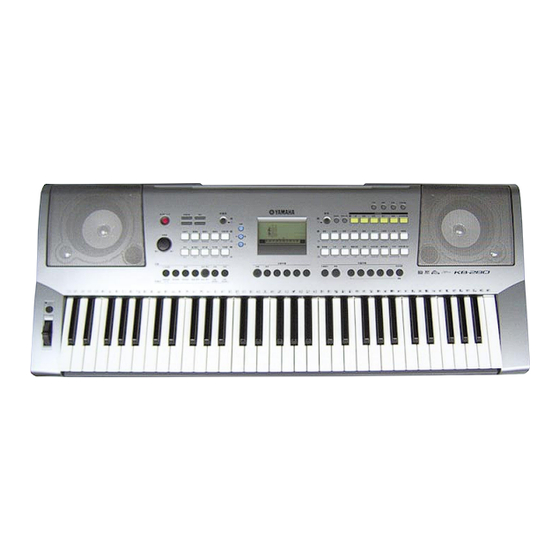
KB-280
SERVICE MANUAL
CONTENTS
SPECIFICATIONS .................................................................3
PANEL LAYOUT .................................................................. 4
CIRCUIT BOARD LAYOUT & WIRING ................................ 6
DISASSEMBLY PROCEDURE ............................................. 8
LSI PIN DESCRIPTION ....................................................... 14
IC BLOCK DIAGRAM ......................................................... 16
CIRCUIT BOARDS .............................................................. 17
TEST PROGRAM ...............................................................26
INITIALIZATION ................................................................. 29
MIDI IMPLEMENTATION CHART ..................................... 30
MIDI DATA FORMAT ......................................................... 31
PARTS LIST
BLOCK DIAGRAM
OVERALL CIRCUIT DIAGRAM
PK
001758
HAMAMATSU, JAPAN
1
Copyright (c) Yamaha Corporation. All rights reserved. PDF
'06.02
Advertisement
Chapters
Table of Contents

Related Manuals for Yamaha PORTATONE KB-280


Summary of Contents for Yamaha PORTATONE KB-280
- Page 1 IC BLOCK DIAGRAM ............16 CIRCUIT BOARDS .............. 17 TEST PROGRAM ...............26 INITIALIZATION ..............29 MIDI IMPLEMENTATION CHART ........30 MIDI DATA FORMAT ............31 PARTS LIST BLOCK DIAGRAM OVERALL CIRCUIT DIAGRAM 001758 HAMAMATSU, JAPAN Copyright (c) Yamaha Corporation. All rights reserved. PDF ’06.02...
-
Page 2: Specifications
IMPORTANT NOTICE This manual has been provided for the use of authorized Yamaha Retailers and their service personnel. It has been assumed that basic service procedures inherent to the industry, and more specifically Yamaha Products, are already known and under- stood by the users, and have therefore not been restated. - Page 3 KB-280 SPECIFICATIONS...
-
Page 4: Panel Layout
KB-280 PANEL LAYOUT Front Panel A’... - Page 5 KB-280 !5 !6 A’ Rear Panel...
-
Page 6: Circuit Board Layout & Wiring
KB-280 CIRCUIT BOARD LAYOUT & WIRING Lower Case Assembly Speaker R Speaker L (AMJK 5/6) Upper case side DMLCD (PN 5/6, 6/6) (PN 5/6, 6/6) !7 y MIDI (AMJK 2/6) (AMJK 1/6) (AMJK 4/6) Upper case assembly Upper case side... - Page 7 KB-280 Connector Unit Name Location Parts No. Destination Remarks Assembly WC601200 61L-CN5 DMLCD-CN402 7P L=550 WG343000 61H-CN2 DMLCD-CN403 5P L=500 WC601000 61H-CN2 DMLCD-CN401 12P L=600 Lower Case Spring Terminal (+) Assembly (V873560) AM-CN151 Spring Terminal (–) Speaker L AM-CN554 (WG32410)
-
Page 8: Disassembly Procedure
KB-280 DISASSEMBLY PROCEDURE Caution: Be sure to attach the removed filament tape just as it was before removal. Lower Case Assembly Spring Terminal (Time required: About 2 minutes) (Time required: About 2 minutes) Remove the battery cover assembly. (Fig. 1) Remove the lower case assembly. - Page 9 KB-280 AM Circuit Board (Time required: About 4 minutes) Remove the “MASTER VOLUME” knob as shown in Fig. 4. (Fig. 4) Remove the lower case assembly. (See procedure 1.) Knob Remove the TW2 connector assembly soldered to the TWL circuit board. (Fig. 5) Remove the seven (7) screws marked [210A], three (Fig.4)
-
Page 10: Amjk
KB-280 DMLCD Circuit Board, Back Light Assembly MIDI Circuit Board and LCD (Time required: About 4 minutes) (Time required: About 6 minutes) Remove the lower case assembly. (See procedure 1.) Remove the lower case assembly. (See procedure 1.) Remove the LCD unit. (See procedure 4.) Remove the four (4) screws marked [210G]. - Page 11 KB-280 PNR Circuit Board 10-2 Set the eight (8) hooks [A] parallel to the groove in (Time required: About 6 minutes) the upper case assembly and remove the SP grille Remove the lower case assembly. (See procedure 1.) L. (Fig. 1, 5) Remove the MIDI circuit board.
- Page 12 KB-280 Disassembling Keyboard Assembly 13-3 Rubber Contacts (Time required: About 12 minutes) 13-3-1 Remove the white and black keys corresponding 13-1 Remove the lower case assembly. (See procedure 1.) to the rubber contacts to be removed. 13-2 White Keys and Black Keys: (See Fig.
- Page 13 KB-280 When installing the circuit board 61H, tighten the screws 1 through 8 in numerical order as shown in the figure for circuit board “61H” in Fig. 14. (Fig. 14) When the black keys from C#2 to A#2, from C#3...
-
Page 14: Lsi Pin Description
KB-280 LSI PIN DESCRIPTION YMW767-VTZ (X6055A00) CPU (SWL01B) ..................14 NT3881DFG-01 (X3148A00) LCD DRIVER ..................15 ML9040A-B01GAZ03A (XZ987A00) LCD DRIVER................15 ADC084S021CIMM (X6905A00) ADC ....................15 AK4385ET (X6040A00) DAC (Digital to Analog Converter) ............... 16 YMW767-VTZ (X6055A00) CPU (SWL01B) DMLCD: IC301... - Page 15 KB-280 NT3881DFG-01 (X3148A00) LCD DRIVER ML9040A-B01GAZ03A (XZ987A00) LCD DRIVER DMLCD: IC601 NAME FUNCTION NAME FUNCTION Data interface Segment signal output for LCD driving Common signal output for LCD driving Ground OSC1 Oscillator OSC2 Oscillator Power supply CLK1 Data latch clock...
-
Page 16: Ic Block Diagram
KB-280 AK4385ET (X6040A00) DAC (Digital to Analog Converter) DMLCD: IC501 NAME NAME FUNCTION FUNCTION AOUTR- Rch Analog out(-) MCLK Master Clock AOUTR+ Rch Analog out(+) BICK Audio Serial Data Clock AOUTL- SDTI Audio Serial Date Input Lch Analog out(-) AOUTL+... -
Page 17: Table Of Contents
KB-280 CIRCUIT BOARDS AM (AMJK 1/6) Circuit Board (X7176C0) ................24 AM (AMJK 4/6) Circuit Board (X7176C0) ................24 AM (AMJK 5/6) Circuit Board (X7176C0) ................24 DMLCD Circuit Board (X7174C0) ..................18/19 MIDI (AMJK 2/6) Circuit Board (X7176C0) ................17 PB (AMJK 6/6) Circuit Board (X7176C0) ................ -
Page 18: Dmlcd Circuit Board (X7174C0)
KB-280 DMLCD Circuit Board not installed to PNL(PN 2/6)-CN774 not installed to 61H-CN1 to 61H-CN2 not installed to 61L-CN5 Component side DMLCD: 2NA-WG23540... - Page 19 KB-280 DMLCD Circuit Board Pattern side DMLCD: 2NA-WG23540...
-
Page 20: Pnr (Pn 1/6) Circuit Board (X7177C0)
KB-280 PNR (PN 1/6) Circuit Board Component side PNR (PN 3/6) Circuit Board PNR: 2NA-WG23610 Component side... - Page 21 KB-280 PNR (PN 1/6) Circuit Board Pattern side PNR (PN 3/6) Circuit Board Pattern side PNR: 2NA-WG23610...
-
Page 22: Pb (Amjk 6/6) Circuit Board (X7176C0)
KB-280 PNL (PN 2/6) Circuit Board to DMLCD-CN703 Component side PNL (PN 4/6) Circuit Board PB (AMJK 6/6) Circuit Board PITCH BEND Component side Component side PB: 2NA-WG23590 PNL: 2NA-WG23610... -
Page 23: Twl (Pn 5/6,6/6) Circuit Board (X7177C0)
KB-280 PNL (PN 2/6) Circuit Board Pattern side TWL, TWR (PN 5/6, 6/6) Circuit Board PNL (PN 4/6) Circuit Board Component side to TWEETER TWL: to AM (AMJK 1/6) -CN553 TWR: to MIDI (AMJK 2/6) -CN556 Pattern side Pattern side... -
Page 24: Am (Amjk 1/6) Circuit Board (X7176C0)
KB-280 AM (AMJK 1/6) Circuit Board to BATTERY Component side DC IN 12V PHONES/ OUTPUT EXPRESSION AM (AMJK 4/6) Circuit Board AM (AMJK 5/6) Circuit Board MASTER VOLUME Component side Component side STANDBY/ON AM: 2NA-WG23590... -
Page 25: Circuit Board (X2335C0)
KB-280 61H Circuit Board to DMLCD-CN401 to 61L-CN4 to DMLCD-CN403 A’ Component side A’ 61L Circuit Board B’ to DMLCD-CN402 to 61H-CN3 B’ Component side 61H: 2NAKB-V869540 61L: 2NAKB-V869520... -
Page 26: Test Program
KB-280 TEST PROGRAM If the test number 47 “Factory Set” is executed, the data already set will be lost. Preparations 1) Use an AC adaptor PA-5D (PA-51). 2) Measuring device: Frequency counter, which can detect thousandth value or more, Level meter (with JIS-C filter) - Page 27 KB-280 Test No. LCD display Test descriptions, judging conditions, etc. SW Chk Checks switches and LEDs on the panel. Press the switches as shown in the LCD. When a switch is pressed, a sound is played at the prescribed pitch. (Refer to the Switch Test Item List on the next page.) When a switch with LED is turned on, the LED will light up.
- Page 28 KB-280 Switch test item list Turn SW Name LCD Display Note Number Turn SW Name LCD Display Note Number Acmp Vol A-VOL UP Strings STRINGS1 Acmp Vol A-VOL DW Violin VIOLIN Tempo TEMPO UP SweetFlt FLUTE Tempo TEMPO DW Clarinet...
-
Page 29: Initialization
KB-280 INITIALIZATION Frash... -
Page 30: Midi Implementation Chart
KB-280 MIDI IMPLEMENTATION CHART YAMAHA [ PortaTone ] Date:17-NOV-2005 Model KB-280 MIDI Implementation Chart Version : 1.0 Transmitted Recognized Remarks Function... Basic Default 1 - 16 1 - 16 Channel Changed Default Mode Messages Altered ************** Note 0 - 127... -
Page 31: Midi Data Format
KB-280 MIDI DATA FORMAT... -
Page 32: Parts List
PARTS LIST CONTENTS OVERALL ASSEMBLY ............. 2 KEYBOARD ASSEMBLY ..........5 LOWER CASE ASSEMBLY ..........6 EXP PEDAL ..............8 ELECTRICAL PARTS ..........9-14 WARNING Components having special characteristics are marked and must be replaced with parts having specification equal to those originally installed. The numbers “QTY”... -
Page 33: Overall Assembly
KB-280 OVERALL ASSEMBLY Music rest Upper case assembly 280a 280b Wheel assembly L110 L100 LCD Unit 340e 340c 340f 340b 340a 340c Battery cover assembly Lower case assembly: See page 6. 340d... - Page 34 KB-280 PART NO. DESCRIPTION REMARKS REF NO. RANK OVERALL ASSEMBLY KB-280 Overall Assembly (WF68200) WF815300 Upper Case Assembly X0159A00 Speaker 3.0cm TWEETER WG307700 Circuit Board WG307800 Circuit Board V 3 6 4 5 5 0 0 Sponge Panel Switch 1 Black...
- Page 35 KB-280 PART NO. DESCRIPTION REMARKS REF NO. RANK L110 Nonwoven Fabric Cloth (V706870) ACCESSORIES WG073800 Music Rest WF324900 AC Adaptor PA-5D CHN EXP Pedal EP-1 KAI (VP62250) : New Parts RANK: Japan only...
-
Page 36: Keyboard Assembly
KB-280 KEYBOARD ASSEMBLY 150a 150c 150b 150d MK Circuit board assembly PART NO. DESCRIPTION REMARKS REF NO. RANK KEYBOARD ASSEMBLY KB-280 V 8 6 9 5 7 0 0 Keyboard Assembly 16N C61 V34107A1 White Key 16N CEGBDFA White Key... -
Page 37: Lower Case Assembly
KB-280 LOWER CASE ASSEMBLY Speaker box L assembly Speaker box R assembly Keyboard assembly: See page 5. Lower case sub assembly... - Page 38 KB-280 PART NO. DESCRIPTION REMARKS REF NO. RANK LOWER CASE ASSEMBLY KB-280 Lower Case Assembly (WG07410) WG074000 Lower Case Sub Assembly V 8 6 9 5 7 0 0 Keyboard Assembly WC601200 Connector Assembly MK3 7P L=550 WG343000 Connector Assembly...
-
Page 39: Exp Pedal
KB-280 EXP PEDAL PART NO. DESCRIPTION REMARKS REF NO. RANK EXP PEDAL EP-1 KB-280 EXP Pedal EP-1 (VP62250) AA049160 Shaft Coil Spring EP-1 (VP60730) CB033200 Metal Holder CB036830 Frame A CB036840 Frame B CB036850 EXP Pedal Plate Actuator EP-1 (VP60740) -
Page 40: Electrical Parts
KB-280 ELECTRICAL PARTS PART NO. DESCRIPTION REMARKS REF NO. RANK ELECTRICAL PARTS KB-280 WG306900 Circuit Board AM (AMJK 1,4,5/6) (WG23590)(X7176C0) WG307000 Circuit Board MIDI (AMJK 2/6) (WG23590)(X7176C0) WG307100 Circuit Board PB (AMJK 6/6) (WG23590)(X7176C0) WG306300 Circuit Board DMLCD (WG23550)(X7174C0) WG307500... - Page 41 KB-280 PART NO. DESCRIPTION REMARKS REF NO. RANK CN853 VZ341900 Cable Holder 51048 9P TE CN855 V I 8 7 8 1 0 0 Cable Holder 51048 3P TE CN855 VZ341600 Cable Holder 51048 3P TE D151 V 8 6 0 3 1 0 0...
- Page 42 KB-280 PART NO. DESCRIPTION REMARKS REF NO. RANK WG306300 Circuit Board DMLCD (WG23550)(X7174C0) C101 US145100 Ceramic Capacitor-F (chip) 0.1000 25V Z RECT. C102 US145100 Ceramic Capacitor-F (chip) 0.1000 25V Z RECT. C103 UF037100 Electrolytic Cap. (chip) 10 16V C104 UF037100 Electrolytic Cap.
- Page 43 KB-280 PART NO. DESCRIPTION REMARKS REF NO. RANK CN401 VK025600 Wire Trap 52147 12P TE CN402 VK025100 Wire Trap 52147 7P TE CN403 VK024900 Wire Trap 52147 5P TE CN701 V J 8 6 1 6 0 0 Wire Trap...
- Page 44 KB-280 PART NO. DESCRIPTION REMARKS REF NO. RANK R727 RD350000 Carbon Resistor (chip) 0 63M J RECT. -732 RD350000 Carbon Resistor (chip) 0 63M J RECT. R746 RD355100 Carbon Resistor (chip) 100.0 63M J RECT. R747 RD357470 Carbon Resistor (chip) 47.0K 63M J RECT.
- Page 45 KB-280 PART NO. DESCRIPTION REMARKS REF NO. RANK X0159A00 Speaker 3.0cm TWEETER X5163A00 Speaker 12.0cm 4ohm 6W WOOFER WF817100 : New Parts RANK: Japan only...
- Page 46 KB-280 BLOCK DIAGRAM KB-280 TOUCH RESPONSE Keybord 61KEY (16N) (AMJK 6/6) (PN 4/6) SW MATRIX (PN 2/6) (PN 1/6) VR751 ( SW 39PCS ) SW771 PA4,PA6,PA7,PC6 SW MATRIX SW701~739 (PN 3/6) ( SW 25PCS ) (C1~B3) (C4~C6) PB0-PB7 LD752 LD751...
- Page 47 KB-280 KB-280 OVERALL CIRCUIT DIAGRAM (AM, DMLCD, MIDI, PB, PNL, PNR, TWL, TWR, 61H, 61L) (PN 2/6) DMLCD (PN 1/6) ROM 128M PROG./WAVE to E-8 TRAD.ACD FR.HORN LUOGU METRO4/4 DRIVER YANGQIN VIVES BRASSECT DIZI1 STRINGS HARP SUONA1 VIOLIN SQUARELD CLASSGTR...
Need help?
Do you have a question about the PORTATONE KB-280 and is the answer not in the manual?
Questions and answers