Table of Contents
Advertisement
Advertisement
Table of Contents

Related Manuals for Asus P5E - AiLifestyle Series Motherboard


Summary of Contents for Asus P5E - AiLifestyle Series Motherboard
- Page 2 Product warranty or service will not be extended if: (1) the product is repaired, modified or altered, unless such repair, modification of alteration is authorized in writing by ASUS; or (2) the serial number of the product is defaced or missing.
-
Page 3: Table Of Contents
Welcome! ..................1-1 Package contents ................. 1-1 Special features ................1-2 1.3.1 Product highlights ............1-2 1.3.2 ASUS AI Lifestyle unique features ........1-4 1.3.3 ASUS Exclusive Overclocking Features ......1-7 Chapter 2: Hardware information Before you proceed ..............2-1 Onboard LED ................. - Page 4 4.1.1 ASUS Update utility ............4-1 4.1.2 Creating a bootable floppy disk ........4-4 4.1.3 ASUS EZ Flash 2 utility ........... 4-5 4.1.4 AFUDOS utility ..............4-6 4.1.5 ASUS CrashFree BIOS 3 utility ........4-8 BIOS setup program ..............4-9 4.2.1...
- Page 5 Contents 4.3.3 Legacy Diskette A ................4-12 4.3.4 Language ..............4-12 4.3.5 SATA 1-6 ............... 4-13 4.3.6 SATA Configuration ............4-14 4.3.7 AHCI Configuration ............4-15 4.3.8 System Information ............4-16 Ai Tweaker menu ................ 4-17 4.4.1 Ai Overclock Tuner ............4-17 4.4.2 CPU Ratio Control ............
- Page 6 Contents Tools menu ................. 4-37 4.8.1 ASUS EZ Flash 2 ............4-37 4.8.2 ASUS O.C. Profile ............4-38 4.8.3 Ai Net 2 ................. 4-39 Exit menu ..................4-40 Chapter 5: Software support Installing an operating system ........... 5-1 Support DVD information ............5-1 5.2.1...
- Page 7 Chapter 6: CrossFire™ technology support ® Overview ..................6-1 6.1.1 Requirements ..............6-1 6.1.2 Before you begin ............. 6-1 Installing CrossFire™ graphics cards ........6-2 Software information ..............6-5 6.3.1 Installing the device drivers ..........6-5 6.3.2 Using the Catalyst™ Control Center ....... 6-7 Appendix: CPU features Intel...
-
Page 8: Notices
Notices Federal Communications Commission Statement This device complies with Part 15 of the FCC Rules. Operation is subject to the following two conditions: • This device may not cause harmful interference, and • This device must accept any interference received including interference that may cause undesired operation. -
Page 9: Safety Information
Safety information Electrical safety • To prevent electrical shock hazard, disconnect the power cable from the electrical outlet before relocating the system. • When adding or removing devices to or from the system, ensure that the power cables for the devices are unplugged before the signal cables are connected. -
Page 10: About This Guide
Refer to the following sources for additional information and for product and software updates. ASUS websites The ASUS website provides updated information on ASUS hardware and software products. Refer to the ASUS contact information. Optional documentation Your product package may include optional documentation, such as warranty flyers, that may have been added by your dealer. -
Page 11: Conventions Used In This Guide
Conventions used in this guide To make sure that you perform certain tasks properly, take note of the following symbols used throughout this manual. DANGER/WARNING: Information to prevent injury to yourself when trying to complete a task. CAUTION: Information to prevent damage to the components when trying to complete a task. -
Page 12: P5E Specifications Summary
4 Processors ® ® Supports Intel next-generation 45nm multi-core CPUs ® Compatible with Intel 06/05B/05A processors ® * Refer to www.asus.com for Intel CPU support list Chipset Intel X38 / ICH9R with Intel Fast Memory Access ® ® Technology System Bus... - Page 13 ASUS AI Lifestyle ASUS Power Saving Solution: Unique features - ASUS EPU (Energy Processing Unit) - ASUS AI Gear 3 (ASUS EPU Utility) - ASUS AI Nap ASUS Quiet Thermal Solution: - ASUS New Generation 8-Phase Power Design - ASUS Fanless Design: Heat-pipe solution...
- Page 14 SM BIOS 2.3, ACPI 2.0a Multi-Language BIOS Manageability WOL by PME, WOR by PME, PXE Software Support DVD: Drivers ASUS PC Probe II ASUS Update ASUS AI Suite Anti-virus software (OEM version) Image-Editing Suite Form Factor ATX Form Factor, 12”x 9.6” (30.5 cm x 24.4 cm)
-
Page 15: Chapter 1: Product Introduction
This chapter describes the motherboard features and the new technologies it supports. Product introduction... - Page 16 Chapter summary Welcome! ..................1-1 Package contents ................. 1-1 Special features ................1-2 ASUS P5E...
-
Page 17: Welcome
® The motherboard delivers a host of new features and latest technologies, making it another standout in the long line of ASUS quality motherboards! Before you start installing the motherboard, and hardware devices on it, check the items in your package with the list below. -
Page 18: Special Features
Green ASUS This motherboard and its packaging comply with the European Union’s Restriction on the use of Hazardous Substances (RoHS). This is in line with the ASUS vision of creating environment-friendly and recyclable products/packaging to safeguard consumers’ health while minimizing the impact on the environment. - Page 19 Native DDR2 1066 memory support To attain top performance, ASUS engineers have successfully unleashed the true potential of DDR2 memory. While in DDR2 1066 mode, ASUS’s exclusive technology offers a choice of FSB 1333, providing great performance for 3D graphics and other memory demanding applications. See page 2-19 for details.
-
Page 20: Asus Ai Lifestyle Unique Features
OS environment, simply click the mouse or press a key. See page 5-21 for details. ASUS Quiet Thermal Solution ASUS Quiet Thermal solution makes system more stable and enhances the overclocking capability. New Generation 8-Phase Power Design The ASUS 8-Phase Power Design provides highly efficient operation to generate less heat (at least 18°C (32.4°F)) than other conventional power... - Page 21 Q-Fan 2 ASUS Q-Fan 2 technology intelligently adjusts both CPU fan and chassis fan speeds according to system loading to ensure quiet, cool and efficient operation. See page 4-28 and 5-23 for details. Fanless Design - Pure Copper Heat-pipe The Heat Pipe design effectively directs the heat generated by the chipsets to the heatsink near the back IO ports, where it can be carried away by existing airflow from CPU fan or bundled optional fan.
- Page 22 ASUS EZ DIY ASUS EZ DIY feature collection provides you easy ways to install computer components, update the BIOS or back up your favorite settings. ASUS AI Direct Link AI Direct Link can easily and efficiently transfer large amounts of data via the network cable - saving up to 70% of the total time taken.
-
Page 23: Asus Exclusive Overclocking Features
Smart Support DVD It provides a checklist to allow the user to see which drivers are already installed, as well as those that aren’t. When using ASUS PC Probe II, you can easily see the critical parts of the computer. - Page 24 Chapter 1: Product Introduction...
-
Page 25: Chapter 2: Hardware Information
This chapter lists the hardware setup procedures that you have to perform when installing system components. It includes description of the jumpers and connectors on the motherboard. Hardware information... - Page 26 Chapter summary Before you proceed ..............2-1 Motherboard overview ..............2-2 Central Processing Unit (CPU) ........... 2-6 System memory ................. 2-14 Expansion slots ................2-19 Switch ..................2-22 Aduio card Installation .............. 2-23 Connectors ................. 2-24 ASUS P5E...
-
Page 27: Before You Proceed
The illustration below shows the location of the onboard LED. SB_PWR ® P5E WS PRO Standby Powered Power P5E WS Professional Onboard LED ASUS P5E... -
Page 28: Motherboard Overview
Motherboard overview Before you install the motherboard, study the configuration of your chassis to ensure that the motherboard fits into it. Make sure to unplug the power cord before installing or removing the motherboard. Failure to do so can cause you physical injury and damage motherboard components. -
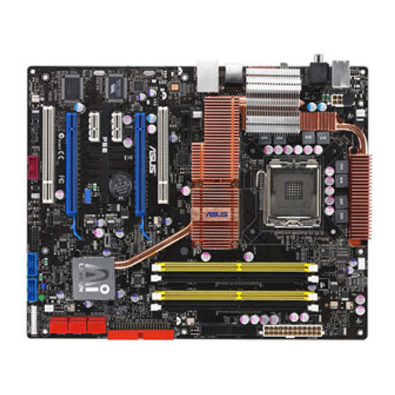
Page 29: Motherboard Layout
SATA34 Super PCIEX16_2 SATA56 BIOS PCI2 CHASSIS CHA_FAN2 IE1394_2 SB_PWR USB910 USB78 PANEL Refer to 2.8 Connectors for more information about rear panel connectors and internal connectors. 2.2.4 Audio card layout FX II UPREME Listen with Absolute HD ASUS P5E... -
Page 30: Layout Contents
2.2.5 Layout contents Slots Page DDR2 DIMM slots 2-14 PCI slots 2-21 PCI Express x 1 slots 2-21 PCI Express 2.0 x 16 slots 2-21 Onboard switch Page Clear RTC RAM (Gaming Level Switch Design) 2-22 Rear panel connectors Page PS/2 keyboard port (purple) 2-24 Coaxial S/PDIF Out port... - Page 31 (4-pin CPU_FAN, 3-pin CHA_FAN1~2, 3-pin PWR_FAN) Chassis intrusion connector (4-1 pin CHASSIS) 2-31 Digital audio connector (4-1 pin SPDIF_OUT for 2-31 ASUS HDMI VGA card) ATX power connectors (24-pin EATXPWR, 8-pin EATX12V) 2-32 System panel connector (20-8 pin PANEL) 2-33...
-
Page 32: Central Processing Unit (Cpu)
ASUS will shoulder the cost of repair only if the damage is shipment/transit-related. • Keep the cap after installing the motherboard. ASUS will process Return Merchandise Authorization (RMA) requests only if the motherboard comes with the cap on the LGA775 socket. -
Page 33: Installing The Cpu
This side of the socket box should face you. To prevent damage to the socket pins, do not remove the PnP cap unless you are installing a CPU. Lift the load lever in the direction of the arrow to a 135º angle. ASUS P5E... - Page 34 Lift the load plate with your thumb and forefinger to a 100º angle (A), then push the PnP cap from the load plate window to remove (B). Load plate Alignment key Position the CPU over the socket, making sure that the gold triangle is on the bottom-left corner of the socket then fit the socket...
-
Page 35: Installing The Cpu Heatsink And Fan
CPU fan connector. Motherboard hole Fastener Narrow end of the groove Make sure to orient each fastener with the narrow end of the groove pointing outward. (The photo shows the groove shaded for emphasis.) ASUS P5E... - Page 36 Push down two fasteners at a time in a diagonal sequence to secure the heatsink and fan assembly in place. Connect the CPU fan cable to the connector on the motherboard labeled CPU_FAN. CPU_FAN ® P5E CPU fan connector DO NOT forget to connect the CPU fan connector! Hardware monitoring errors can occur if you fail to plug this connector.
-
Page 37: Uninstalling The Cpu Heatsink And Fan
Rotate each fastener counterclockwise. Pull up two fasteners at a time in a diagonal sequence to disengage the heatsink and fan assembly from the motherboard. Carefully remove the heatsink and fan assembly from the motherboard. ASUS P5E 2-11... - Page 38 Rotate each fastener clockwise to ensure correct orientation when reinstalling. Narrow end of the groove The narrow end of the groove should point outward after resetting. (The photo shows the groove shaded for emphasis.) Refer to the documentation in the boxed or stand-alone CPU fan package for detailed information on CPU fan installation.
-
Page 39: Installing The Optional Fans
• Plug the optional fan cables to any of the CHA_FAN1, CHA_FAN3, and PWR_FAN connectors on the motherboard. • Make sure the optional fan is installed correctly to prevent damage to the fan and motherboard components. ASUS P5E 2-13... -
Page 40: System Memory
Sockets Channel A DIMM_A1 and DIMM_A2 Channel B DIMM_B1 and DIMM_B2 • This chipset officially supports DDR2-800 MHz. With the ASUS Super Memspeed Technology, this motherboard natively supports up to DDR2-1066 MHz. See the table below. DDR2 1333 1066* 1333... -
Page 41: Memory Configurations
DDR2-667. If this happens, contact your memory vendor to check the ODT value. • Due to chipset limitation, DDR2-800 with CL=4 will be downgraded to run at DDR2-667 by default setting. If you want to operate with lower latency, adjust the memory timing manually. ASUS P5E 2-15... - Page 42 P5E Motherboard Qualified Vendors Lists (QVL) DDR2-800 MHz capability DIMM socket support Chip (Optional) Size Vendor Chip No. DS Part No. Brand 512MB KINGSTON K4T51083QC SS KVR800D2N5/512 1024MB KINGSTON Heat-Sink Package 4-4-4-12 N/A DS KHX6400D2LL/1G 1024MB KINGSTON V59C1512804QBF25 DS KVR800D2N5/1G 1024MB KINGSTON Heat-Sink Package...
- Page 43 Supports one pair of modules inserted into either Channel A or Channel B as one pair of Dual-channel memory configuration. Supports four modules inserted into the orange and black slots as two pairs of Dual-channel memory configuration. Visit the ASUS website for the latest DDR2 QVL. ASUS P5E 2-17...
-
Page 44: Installing A Dimm
2.4.3 Installing a DIMM Unplug the power supply before adding or removing DIMMs or other system components. Failure to do so can cause severe damage to both the motherboard and the components. To install a DIMM: DDR2 DIMM notch Unlock a DIMM socket by pressing the retaining clips outward. -
Page 45: Expansion Slots
IRQ” or that the cards do not need IRQ assignments. Otherwise, conflicts will arise between the two PCI groups, making the system unstable and the card inoperable. Refer to the table on the next page for details. ASUS P5E 2-19... -
Page 46: Interrupt Assignments
2.5.3 Interrupt assignments Priority Standard function System timer Keyboard controller – Re-direct to IRQ#9 IRQ holder for PCI steering* Communications port (COM1)* IRQ holder for PCI steering* Floppy disk controller Printer port (LPT1)* System CMOS/Real Time Clock IRQ holder for PCI steering* IRQ holder for PCI steering* IRQ holder for PCI steering* PS/2 compatible mouse port*... -
Page 47: Pci Slots
Install two ATI graphics cards from the same GPU family that support CrossFire™ mode. • If you install two VGA cards, we recommend that you plug the rear chassis fan cable to the motherboard connector labeled CHA_FAN1/3 for better thermal environment. See page 2-36 for the connector location. ASUS P5E 2-21... -
Page 48: Switch
Switch Clear RTC RAM (Gaming Level Switch Design) This switch allows you to clear the Real Time Clock (RTC) RAM in CMOS. You can clear the CMOS memory of date, time, and system setup parameters by erasing the CMOS RTC RAM data. The onboard button cell battery powers the RAM data in CMOS, which include system setup information such as system passwords. -
Page 49: Audio Card Installation
Locate the audio slot on the package. motherboard. Align the card connector with the The photo below shows the slot and press firmly until the card audio card installed on the sits on the slot completely. motherboard. 2-23 ASUS P5E... -
Page 50: Connectors
Connectors 2.8.1 Rear panel connectors PS/2 keyboard port (purple). This port is for a PS/2 keyboard. Coaxial S/PDIF Out port. This port connects an external audio output device via a coaxial S/PDIF cable. LAN (RJ-45) port. This port allows Gigabit connection to a Local Area Network (LAN) through a network hub. - Page 51 13. Optical S/PDIF Out port. This port connects an external audio output device via an optical S/PDIF cable. 14. USB 2.0 ports 5 and 6. These 4-pin Universal Serial Bus (USB) ports are available for connecting USB 2.0 devices. 2-25 ASUS P5E...
-
Page 52: Internal Connectors
2.8.2 Internal connectors Floppy disk drive connector (34-1 pin FLOPPY) This connector is for the provided floppy disk drive (FDD) signal cable. Insert one end of the cable to this connector, then connect the other end to the signal connector at the back of the floppy disk drive. Pin 5 on the connector is removed to prevent incorrect cable connection when using a FDD cable with a covered Pin 5. - Page 53 Ultra DMA cable connector. This prevents incorrect insertion when you connect the IDE cable. • Use the 80-conductor IDE cable for Ultra DMA 133/100 IDE devices. If any device jumper is set as “Cable-Select,” make sure all other device jumpers have the same setting. 2-27 ASUS P5E...
- Page 54 ICH9R Serial ATA connectors (7-pin SATA1~6) These connectors are for the Serial ATA signal cables for Serial ATA hard disk drives. If you installed Serial ATA hard disk drives, you can create a RAID 0, RAID 1, RAID 5, RAID 10 configuration with the Intel Matrix Storage Technology ®...
- Page 55 Never connect a 1394 cable to the USB connectors. Doing so will damage the motherboard! You can connect the USB cable to ASUS Q-Connector (USB, blue) first, and then install the Q-Connector (USB) to the USB connector onboard. IEEE 1394a port connector (10-1 pin IE1394_2) This connector is for a IEEE 1394a port.
- Page 56 P5E Fan connectors • Only the CPU_FAN, CHA_FAN1~3, and OPT_FAN1~3 connectors support the ASUS Q-Fan 2 feature. • If you install two VGA cards, we recommend that you plug the chassis fan cable to the motherboard connector labled CHA_FAN1 or CHA_FAN3 for better themal environment.
- Page 57 Digital audio connector (4-1 pin SPDIF_OUT for ASUS HDMI VGA card) This connector is for an additional Sony/Philips Digital Interface (S/PDIF) port(s). If you are using an ASUS HDMI-equipped graphics card, connect the HDMI card to this connector with a S/PDIF Out cable.
- Page 58 Pentium Extreme 3.73GHz ® ® Memory: 512 MB DDR2 (x4) Graphics card: ASUS EAX1900XT Parallel ATA device: IDE hard disk drive Serial ATA device: SATA hard disk drive (x2) Optical drive: DVD-RW • If you want to use two high-end PCI Express x16 cards, use a PSU with 500W to 600W power or above to ensure the system stability.
-
Page 59: System Panel Connector
BIOS settings. Pressing the power switch for more than four seconds while the system is ON turns the system OFF. • Reset button (2-pin RESET) This 2-pin connector is for the chassis-mounted reset button for system reboot without turning off the system power. ASUS P5E 2-33... -
Page 60: Asus Q-Connector
ASUS Q-Connector (system panel) You can use the ASUS Q-Connector to connect/disconnect chassis front panel cables in a few steps. Refer to the instructions below to install the ASUS Q- Connector. Connect the front panel cables to the ASUS Q-Connector. -
Page 61: Chapter 3: Powering Up
This chapter describes the power up sequence, the vocal POST messages, and ways of shutting down the system. Powering up... - Page 62 Chapter summary Starting up for the first time ............3-1 Turning off the computer ............. 3-2 ASUS P5E...
-
Page 63: Starting Up For The First Time
One continuous beep followed by three No VGA detected short beeps One continuous beep followed by four Hardware component failure short beeps At power on, hold down the <Delete> key to enter the BIOS Setup. Follow the instructions in Chapter 4. ASUS P5E... -
Page 64: Turning Off The Computer
Turning off the computer 3.2.1 Using the OS shut down function If you are using Windows ® Click the Start button then select Turn Off Computer. Click the Turn Off button to shut down the computer. The power supply should turn off after Windows ®... -
Page 65: Chapter 4: Bios Setup
This chapter tells how to change the system settings through the BIOS Setup menus. Detailed descriptions of the BIOS parameters are also provided. BIOS setup... - Page 66 Managing and updating your BIOS ..........4-1 BIOS setup program ..............4-9 Main menu .................. 4-12 Ai Tweaker .................. 4-17 Advanced menu ................. 4-23 Power menu ................4-29 Boot menu .................. 4-33 Tools menu ................. 4-37 Exit menu ..................4-40 ASUS P5E...
-
Page 67: Managing And Updating Your Bios
® ASUS EZ Flash 2 (Updates the BIOS using a floppy disk or USB flash disk.) ASUS AFUDOS (Updates the BIOS using a bootable floppy disk) ASUS CrashFree BIOS 3 (Updates the BIOS using a USB flash disk or the motherboard support DVD when the BIOS file fails or gets corrupted.) - Page 68 To update the BIOS through the Internet: desktop by clicking Start Launch the ASUS Update utility from the Windows ® > Programs > ASUS > ASUSUpdate > ASUSUpdate. The ASUS Update main window appears. Select Update BIOS from the Select the ASUS FTP site nearest...
- Page 69 To update the BIOS through a BIOS file: desktop by clicking Start Launch the ASUS Update utility from the Windows ® > Programs > ASUS > ASUSUpdate > ASUSUpdate. The ASUS Update main window appears. Select Update BIOS from a file option from the drop-down menu, then click Next.
-
Page 70: Creating A Bootable Floppy Disk
4.1.2 Creating a bootable floppy disk Do either one of the following to create a bootable floppy disk. DOS environment a. Insert a 1.44MB floppy disk into the drive. b. At the DOS prompt, type format A:/S then press <Enter>. Windows XP environment ®... -
Page 71: Asus Ez Flash 2 Utility
4.1.3 ASUS EZ Flash 2 utility The ASUS EZ Flash 2 feature allows you to update the BIOS without having to go through the long process of booting from a floppy disk and using a DOS-based utility. The EZ Flash 2 utility is built-in the BIOS chip so it is accessible by pressing <Alt>... -
Page 72: Afudos Utility
Updating the BIOS file To update the BIOS file using the AFUDOS utility: Visit the ASUS website (www.asus.com) and download the latest BIOS file for the motherboard. Save the BIOS file to a bootable floppy disk. Chapter 4: BIOS setup... - Page 73 A:\>afudos /iP5E.ROM The utility verifies the file and starts updating the BIOS. A:\>afudos /iP5E.ROM AMI Firmware Update Utility - Version 1.19(ASUS V2.07(03.11.24BB)) Copyright (C) 2002 American Megatrends, Inc. All rights reserved. WARNING!! Do not turn off power during flash BIOS Reading file ..done Reading flash ..
-
Page 74: Asus Crashfree Bios 3 Utility
4.1.5 ASUS CrashFree BIOS 3 utility The ASUS CrashFree BIOS 3 is an auto recovery tool that allows you to restore the BIOS file when it fails or gets corrupted during the updating process. You can update a corrupted BIOS file using the motherboard support DVD or the USB flash disk that contains the updated BIOS file. -
Page 75: Bios Setup Program
The BIOS setup screens shown in this section are for reference purposes only, and may not exactly match what you see on your screen. • Visit the ASUS website (www.asus.com) to download the latest BIOS file for this motherboard. ASUS P5E... -
Page 76: Bios Menu Screen
4.2.1 BIOS menu screen Menu items Menu bar Configuration fields General help BIOS SETUP UTILITY Main Ai Tweaker Advanced Power Boot Tools Exit Use [ENTER], [TAB] System Time [10:55:25] or [SHIFT-TAB] to System Date [Mon 07/23/2007] select a field. Legacy Diskette A [1.44M, 3.5 in.] Language [English]... -
Page 77: Menu Items
Up/Down arrow keys or <Page Up> /<Page Down> keys to display the other items on the screen. 4.2.9 General help Pop-up window At the top right corner of the menu screen Scroll bar is a brief description of the selected item. ASUS P5E 4-11... -
Page 78: Main Menu
Main menu When you enter the BIOS Setup program, the Main menu screen appears, giving you an overview of the basic system information. Refer to section 4.2.1 BIOS menu screen for information on the menu screen items and how to navigate through them. BIOS SETUP UTILITY Main Ai Tweaker... -
Page 79: Sata 1-6
When set to [Disabled], the data transfer from and to the device occurs one sector at a time. Configuration options: [Disabled] [Auto] PIO Mode [Auto] Allows you to select the data transfer mode. Configuration options: [Auto] [0] [1] [2] [3] [4] ASUS P5E 4-13... -
Page 80: Sata Configuration
DMA Mode [Auto] Selects the DMA mode. Configuration options: [Auto] [SWDMA0] [SWDMA1] [SWDMA2] [MWDMA0] [MWDMA1] [MWDMA2] [UDMA0] [UDMA1] [UDMA2] [UDMA3] [UDMA4] [UDMA5] SMART Monitoring [Auto] Sets the Smart Monitoring, Analysis, and Reporting Technology. Configuration options: [Auto] [Disabled] [Enabled] 32Bit Data Transfer [Enabled] Enables or disables 32-bit data transfer. -
Page 81: Ahci Configuration
SATA Port1 [Auto] Allows you to select the type of device connected to the system. Configuration options: [Auto] [Not Installed] SMART Monitoring [Enabled] Allows you to set the Self-Monitoring, Analysis and Reporting Technology. Configration options: [Disabled] [Enabled] ASUS P5E 4-15... -
Page 82: System Information
4.3.8 System Information This menu gives you an overview of the general system specifications. The BIOS automatically detects the items in this menu. BIOS SETUP UTILITY Main ASUS BIOS Version : 0102 Build Date : 08/24/07 Processor Type : Intel(R) Core(TM)2 Duo @ CPU 3.00GHz... -
Page 83: Ai Tweaker Menu
Memory Profile [Disabled] This item appears only when you set the Ai Overclock Tuner item to [X.M.P.]. Allows you to select the X.M.P. mode supported by your Memory module. Configuration options: [Disabled] [Profile #1] [Profile #2] ASUS P5E 4-17... -
Page 84: Cpu Ratio Control
4.4.2 CPU Ratio Control [Auto] Configuration options: [Auto] [Manual]. Ratio CMOS Setting [9] This sub-item appears only when you set the CPU Ratio Control item to [Manual]. Allows you to set the ratio between CPU Core Clock and FSB Frequency. Use the <+> and <-> keys to adjust the ratio. If an invalid ratio is set in CMOS, then actual and setpoint values may differ. -
Page 85: Dram Frequency
Configuration options: [Auto] [20 DRAM Clocks] [25 DRAM Clocks] [30 DRAM Clocks] [35 DRAM Clocks] [42 DRAM Clocks] Write Recovery Time [Auto] Configuration options: [Auto] [1 DRAM Clocks]~[15 DRAM Clocks] Write to Read Delay [Auto] Configuration options: [Auto] [1 DRAM Clocks]~[15 DRAM Clocks] ASUS P5E 4-19... -
Page 86: Dram Static Read Control
Read to Precharge Time [Auto] Configuration options: [Auto] [1 DRAM Clocks]~[15 DRAM Clocks] 4.4.6 DRAM Command Rate [Auto] Configuration options: [Auto] [1T] [2T] 4.4.7 DRAM Static Read Control [Auto] Configuration options: [Auto] [Disabled] [Enabled] 4.4.8 Transaction Booster [Auto] Configuration options: [Auto] [Disabled] [Enabled] Boost Level [0] This sub-item appears only when you set the Transaction Booster item to [Enabled]. - Page 87 The following three items appear when you set the Ai Overclock Tuner item to [Manual] and [X.M.P.]. CPU Voltage Damper [Auto] Allows you to enable or disable the CPU voltage damper. Configuration options: [Auto] [Disabled] [Enabled] CPU Voltage Reference [Auto] Configuration options: [Auto] [0.63x] [0.61x] [0.59x] [0.57x] ASUS P5E 4-21...
-
Page 88: Cpu Spread Spectrum
North Bridge Voltage Reference [Auto] Configuration options: [Auto] [0.67x] [0.63x] [0.60x] [0.57x] [0.56x] [0.53x] [0.51x] [0.49x] SB 1.5V Voltage [Auto] Configuration options: [Auto] [1.50V] [1.55V] [1.60V] [1.65V] [1.70V] [1.75V] [1.80V] VCC EXT PLL OV [Auto] Configuration options: [Auto] [Disabled] [Enabled] 4.4.9 CPU Spread Spectrum [Auto] Allows you to disable or set to auto the CPU clock spread spectrum. -
Page 89: Advanced Menu
General Help Intel(R) SpeedStep(TM) Tech. [Enabled] Save and Exit Exit v02.61 (C)Copyright 1985-2007, American Megatrends, Inc. CPU Ratio Control [Auto] Configuration options: [Auto] [Manual] The following item appears when the item CPU Ratio Control is set to [Manual]. ASUS P5E 4-23... - Page 90 Ratio CMOS Setting: [9] Allows you to set the ratio between the CPU Core Clock and the FSB Frequency. Use <+> and <-> to adjust the value. Configuration options: [ 6] [ 7] [ 8] [ 9] The options vary depending on the CPU you install. C1E Support [Enabled] Allows you to enable or disable C1E Support.
-
Page 91: Chipset
Allows you to decide which graphics controller to use as the primary boot device. Configuration options: [PCI/PEG] [PEG/PCI] PEG Port Control [Auto] Configuration options: [Auto] [Disabled] The following item appears only when you set PEG Port Control to [Auto] PEG Port Force x1 [Disabled] Configuration options: [Enabled] [Disabled] ASUS P5E 4-25... -
Page 92: Onboard Device Configuration
4.5.3 Onboard Device Configuration BIOS SETUP UTILITY Advanced Onboard Device Configuration High Definition Audio [Enabled] Enable or Disable Front Panel Type [HD Audio] High Definition Audio J-Micron PATA Controller [Enabled] Controller Marvell GigaBit LAN [Enabled] LAN Boot ROM [Disabled] VIA 1394 [Enabled] Select Screen Select Item... -
Page 93: Usb Configuration
Configuration options: [Disabled] [Enabled] Port 64/60 Emulation [Disabled] Allows you to enable or disable the I/O port 60h/64h emulation support. This item should be enabled for the complete USB keyboard legacy support for non-USB aware OSes. Configuration options: [Disabled] [Enabled] ASUS P5E 4-27... -
Page 94: Pcipnp
Legacy USB Support [Auto] Allows you to enable or disable the support for legacy USB devices. Setting to [Auto] allows the system to detect the presence of USB devices at startup. If detected, the USB controller legacy mode is enabled. If no USB device is detected, the legacy USB support is disabled. -
Page 95: Power Menu
Allows you to enable or disable the Advanced Configuration and Power Interface (ACPI) support in the Advanced Programmable Interrupt Controller (APIC). When set to [Enabled], the ACPI APIC table pointer is included in the RSDT pointer list. Configuration options: [Disabled] [Enabled] ASUS P5E 4-29... -
Page 96: Apm Configuration
4.6.5 APM Configuration BIOS SETUP UTILITY Power APM Configuration <Enter> to select whether or not to restart the system Restore on AC Power Loss [Power Off] after AC power loss. Power On By RTC Alarm [Disabled] Power On By PCI Devices [Disabled] Power On By PCIE Devices [Disabled]... -
Page 97: Hardware Monitor
The following item appears only when you enable CPU Q-Fan Control. CPU Fan Profile [Optimal] Allows you to set the appropriate performance level of the ASUS Q-Fan. When set to [Optimal], the CPU fan automatically adjusts depending on the CPU temperature. - Page 98 Chassis Q-Fan Controls [Disabled] Allows you to enable or disable the Chassis Q-fan. Configuration options: [Disabled] [Enabled] The following items appear only when you enable Chassis Q-Fan Control. Chassis Fan Ratio [Auto] Allows you to select a fan speed ratio in the low CPU temperature. Configuration options [Auto] [90%] [80%] [70%] [60%] A very low fan speed ratio may cause fan speed drop and trigger the hardware monitor warning message.
-
Page 99: Boot Menu
These items specify the boot device priority sequence from the available devices. The number of device items that appears on the screen depends on the number of devices installed in the system. Configuration options: [1st FLOPPY DRIVE] [Hard Drive] [ATAPI DVD-ROM] [Disabled] ASUS P5E 4-33... -
Page 100: Boot Settings Configuration
This allows you to enable or disable the full screen logo display feature. Configuration options: [Disabled] [Enabled] Set this item to [Enabled] to use the ASUS MyLogo3™ feature. AddOn ROM Display Mode [Force BIOS] Sets the display mode for option ROM. -
Page 101: Security
If you forget your BIOS password, you can clear it by erasing the CMOS Real Time Clock (RTC) RAM. See section 2.6 Jumper for information on how to erase the RTC RAM. After you have set a supervisor password, the other items appear to allow you to change other security settings. ASUS P5E 4-35... -
Page 102: Change User Password
BIOS SETUP UTILITY Boot Security Settings <Enter> to change password. Supervisor Password : Installed <Enter> again to User Password : Installed disabled password. Change Supervisor Password User Access Level [Full Access] Change User Password Clear User Password Password Check [Setup] Select Screen Select Item Enter Change... -
Page 103: Tools Menu
4.8.1 ASUS EZ Flash 2 Allows you to run ASUS EZ Flash 2. When you press <Enter>, a confirmation message appears. Use the left/right arrow key to select between [Yes] or [No], then press <Enter> to confirm your choice. Please see page 4-4, section 4.1.2 for details. -
Page 104: Asus O.c. Profile
4.8.2 ASUS O.C. Profile This item allows you to store or load multiple BIOS settings. BIOS SETUP UTILITY Tools O.C. PROFILE Configuration Save to Profile 1 O.C. Profile 1 Status : Not Installed O.C. Profile 2 Status : Not Installed... -
Page 105: Ai Net 2
N/A Marvell POST Check LAN cable [Disabled] v02.61 (C)Copyright 1985-2007, American Megatrends, Inc. Marvell POST Check LAN Cable [Disabled] Enables or disables checking of the Marvell LAN cable during the Power-On Self-Test (POST). Configuration options: [Disabled] [Enabled] ASUS P5E 4-39... -
Page 106: Exit Menu
Exit menu The Exit menu items allow you to load the optimal or failsafe default values for the BIOS items, and save or discard your changes to the BIOS items. BIOS SETUP UTILITY Main Ai Tweaker Advanced Power Boot Tools Exit Exit system setup after Exit &... -
Page 107: Chapter 5: Software Support
This chapter describes the contents of the support DVD that comes with the motherboard package. Software support... - Page 108 Chapter summary Installing an operating system ........... 5-1 Support DVD information ............5-1 Software information ..............5-9 RAID configurations ..............5-35 Creating a RAID driver disk ............5-44 ASUS P5E...
-
Page 109: Installing An Operating System
The contents of the support DVD are subject to change at any time without notice. Visit the ASUS website (www.asus.com) for updates. 5.2.1 Running the support DVD Place the support DVD to the optical drive. -
Page 110: Drivers Menu
USB 2.0 Driver Installs the Universal Serial Bus 2.0 (USB 2.0) driver. ASUS EPU + AI Gear 3 Driver Installs the EPU + AI Gear 3 driver. Install this driver before the ASUS AI Suite utility. Chapter 5: Software support... -
Page 111: Utilities Menu
ASUS AI Suite Installs the ASUS AI Suite. ASUS Update The ASUS Update utility allows you to update the motherboard BIOS in Windows ® environment. This utility requires an Internet connection either through a network or an Internet Service Provider (ISP). - Page 112 You can also install the following utilities from the ASUS Superb Software Library DVD. Anti-Virus Utility The anti-virus application detects and protects your computer from viruses that destroys data. You can also download the utility by clicking the Security tab.
-
Page 113: Make Disk Menu
5.2.4 Make Disk menu The Make Disk menu contains items to create the Intel ICH9R or JMicron JMB368 ® RAID/AHCI driver disk. Intel ICH9 32/64 bit RAID/AHCI Driver Allows you to create an ICH9R 32/64bit RAID/AHCI driver disk. ASUS P5E... -
Page 114: Manuals Menu
Reader from the Utilities menu before opening a user manual ® ® file. 5.2.6 ASUS Contact information Click the Contact tab to display the ASUS contact information. You can also find this information on the inside front cover of this user guide. Chapter 5: Software support... -
Page 115: Other Information
The icons on the top right corner of the screen give additional information on the motherboard and the contents of the support DVD. Click an icon to display the specified information. Motherboard Info Displays the general specifications of the motherboard. Browse this DVD Displays the support DVD contents in graphical format. ASUS P5E... -
Page 116: Technical Support Form
Technical support form Displays the ASUS Technical Support Request Form that you have to fill out when requesting technical support. Filelist Displays the contents of the support DVD and a brief description of each in text format. Chapter 5: Software support... -
Page 117: Software Information
Before using the ASUS MyLogo3 , use the AFUDOS utility to make a copy ™ of your original BIOS file, or obtain the latest BIOS version from the ASUS website. See section 4.1.4 AFUDOS utility. • Make sure that the BIOS item Full Screen Logo is set to [Enabled] if you wish to use ASUS MyLogo3™. - Page 118 Ratio box. When the screen returns to the ASUS Update utility, flash the original BIOS to load the new boot logo. 10. After flashing the BIOS, restart the computer to display the new boot logo during POST.
-
Page 119: Ai Net 2
LAN cable(s) connected to the LAN port(s). • If you want the system to check the status of the LAN cable before entering the OS, enable the item Post Check LAN Cable in the BIOS Setup. ASUS P5E 5-11... -
Page 120: Ai Audio 2 (Soundmax ® High Definition Audio Utility)
5.3.3 AI Audio 2 (SoundMAX High Definition Audio utility) ® The ADI AD1988B High Definition Audio CODEC provides 8-channel audio capability through the SoundMAX audio utility with AudioESP™ software to ® deliver the ultimate audio experience on your PC. The software implements high quality audio synthesis/rendering, 3D sound positioning, and advanced voice-input technologies. - Page 121 Surround Virtualization Activating this function virtualizes surround sound with the vocal clarity added for use with stereo speakers or headphones. SoundMAX BlackHawk (AI Audio2) is available only under the Windows ® Vista™ operating system. ASUS P5E 5-13...
- Page 122 Playback Settings To configure the playback settings, click the Playback button on the control panel. You can adjust the volume of the Speakers and SPDIF Interface or mute the audio. Preset settings Click and expand the drop-down menu to select your preferred Digital Signal Processing (DSP) preset.
- Page 123 Allows you to select an enhanced microphone input features, including No Filtering, Speakerphone, Voice Recording, and Directional Beam. More Settings Click for the further configurations. Equalizer Allows you to configure and customize all the DSP presets frequencies. ASUS P5E 5-15...
- Page 124 Speakers Allows you to adjust the Speaker Trim and Speaker Delay. Bass Allows you to do the Bass management. Preferences Displays the preference options for this utility, version information, AudioESP, etc. 5-16 Chapter 5: Software support...
- Page 125 SoundMAX Control Panel. ® ® Audio Setup Wizard By clicking the icon from the SoundMAX control panel, you can ® easily configure your audio settings. Simply follow the succeeding screen instructions and begin enjoying High Definition Audio. ASUS P5E 5-17...
- Page 126 Jack configuration Adjust speaker volume This screen helps you configure This screen helps you adjust speaker volume. Click the Test your computer’s audio ports, depending on the audio devices button to hear the changes you you have installed. have made. Adjust microphone volume This screen helps you adjust microphone volume.
- Page 127 Click the General tab to choose your playback and recording devices, enable/ disable the AudioESP™ feature, and enable/disable digital output. Listening Environment options Click the Listening Environment tab to set up your speaker, acoustic environment, and enable/disable the Virtual Theater Surround function. ASUS P5E 5-19...
- Page 128 Microphone options Click the Microphone tab allows you to optimize your microphone input settings. 5-20 Chapter 5: Software support...
-
Page 129: Asus Pc Probe Ii
To launch the PC Probe II from the Windows ® > ASUS > PC Probe II > PC Probe II v1.xx.xx. The PC Probe II main window appears. After launching the application, the PC Probe II icon appears in the Windows ®... - Page 130 Button Function Opens the Configuration window Opens the Report window Opens the Desktop Management Interface window Opens the Peripheral Component Interconnect window Opens the Windows Management Instrumentation window Opens the hard disk drive, memory, CPU usage window Shows/Hides the Preference section Minimizes the application Closes the application Sensor alert...
- Page 131 Click to clicking the or buttons. You can increase also adjust the threshold values value using the Config window. Click to You cannot adjust the sensor decrease threshold values in a small value monitoring panel. ASUS P5E 5-23...
- Page 132 Monitoring sensor alert The monitor panel turns red when a component value exceeds or is lower than the threshold value. Refer to the illustrations below. Small display Large display WMI browser Click to display the WMI (Windows Management Instrumentation) browser. This browser displays various Windows®...
- Page 133 The left panel of the tab lists all logical drives. Click a hard disk drive to display the information on the right panel. The pie chart at the bottom of the window represents the used (blue) and the available HDD ASUS P5E 5-25...
- Page 134 Memory usage The Memory tab shows both used and available physical memory. The pie chart at the bottom of the window represents the used (blue) and the available Configuring PC Probe II Click to view and adjust the sensor threshold values. The Config window has two tabs: Sensor/Threshold and Preference.
-
Page 135: Asus Ai Suite
5.3.5 ASUS AI Suite ASUS AI Suite allows you to launch AI Gear 2, AI N.O.S., AI Booster, AI Nap, and Q-Fan 2 utilities easily. Install the ASUS EPU + AI Gear 3 Driver before the ASUS AI Suite utility. - Page 136 Other feature buttons Click on right corner of the main window to open the monitor window. Displays the CPU/ system temperature, CPU/memory/PCIE voltage, and CPU/ chassis fan speed Displays the FSB/CPU frequency Click on right corner of the expanded window to switch the temperature from degrees Centigrade to degrees Fahrenheit.
-
Page 137: Asus Ai Gear 3
5.3.6 ASUS AI Gear 3 (ASUS EPU Utility) ASUS AI Gear 3 is a utility designed to configure and support all ASUS EPU (Energy Processing Unit) features. This easy-to-use utility provides four system performance profiles that adjusts the processor frequency and vCore voltage for different computing needs. -
Page 138: Asus Ai Nap
5.3.7 ASUS AI Nap This feature allows you to minimize the power consumption of your computer whenever you are away. Enable this feature for minimum power consumption and a quieter system operation. After installing AI Suite from the bundled Support DVD, you can launch the utility by double-clicking the AI Suite icon on the Windows OS taskbar and click the AI Nap button on the AI Suite main window. -
Page 139: Asus Q-Fan 2
5.3.8 ASUS Q-Fan 2 This ASUS Q-Fan 2 Control feature allows you to set the appropriate performance level of the CPU Q-Fan 2 or the Chassis Q-Fan 2 for more efficient system operation. After enabling the Q-Fan 2 function, the fans can be set to automatically adjust depending on the temperature, to decrease fan speed, or to achieve the maximum fan speed. -
Page 140: Asus Ai Booster
5.3.9 ASUS AI Booster The ASUS AI Booster application allows you to overclock the CPU speed in WIndows environment without the hassle of booting the BIOS. ® After installing AI Suite from the bundled Support DVD, you can launch the utility... -
Page 141: Asus Ai Direct Link
You must first connect two computers (at least one of them is ASUS product) using a network cable, and then install the utility to both computers to avail the AI Direct Link feature. - Page 142 The default path of the AIDirectLinkIncoming folder is C:\Program Files\ASUS\AI Direct Link. To change its location, disable the incoming folder first. Then, select Incoming folder > Change incoming folder to open the system directories, and move the AIDirectLinkIncoming folder under another directory.
-
Page 143: Raid Configurations
RAID configurations The motherboard comes with the Intel ICH9R Southbridge RAID controller that ® allows you to configure IDE and Serial ATA hard disk drives as RAID sets. 5.4.1 RAID definitions RAID 0 (Data striping) optimizes two identical hard disk drives to read and write data in parallel, interleaved stacks. -
Page 144: Installing Serial Ata Hard Disks
5.4.2 Installing Serial ATA hard disks The motherboard supports Serial ATA hard disk drives. For optimal performance, install identical drives of the same model and capacity when creating a disk array. To install the SATA hard disks for a RAID configuration: Install the SATA hard disks into the drive bays. -
Page 145: Intel Matrix Storage Manager Option Rom Utility
Intel Matrix Storage Manager Option ROM Utility ® The Intel Matrix Storage Manager Option ROM utility allows you to create RAID 0, ® RAID 1, RAID 10 (RAID 0+1), and RAID 5 set(s) from Serial ATA hard disk drives that are connected to the Serial ATA connectors supported by the Southbridge. To enter the Intel ®... -
Page 146: Creating A Raid 0 Set (Striped)
Creating a RAID 0 set (striped) To create a RAID 0 set: From the utility main menu, select 1. Create RAID Volume, then press <Enter>. This screen appears. Intel(R) Matrix Storage Manager Option ROM v5.0.0.1032 ICH9R wRAID5 Copyright(C) 2003-05 Intel Corporation. All Rights Reserved. [ CREATE ARRAY MENU ] Name:... - Page 147 Use the up/down arrow key to select the stripe size for the RAID 0 array, then press <Enter>. The available stripe size values range from 4 KB to 128 KB. The default stripe size is 128 KB. TIP: We recommend a lower stripe size for server systems, and a higher stripe size for multimedia computer systems used mainly for audio and video editing.
-
Page 148: Creating A Raid 1 Set (Mirrored)
Creating a RAID 1 set (mirrored) To create a RAID 1 set: From the utility main menu, select 1. Create RAID Volume, then press <Enter>. This screen appears. Intel(R) Matrix Storage Manager Option ROM v5.0.0.1032 ICH9R wRAID5 Copyright(C) 2003-05 Intel Corporation. All Rights Reserved. [ CREATE ARRAY MENU Name: Volume1... - Page 149 Creating a RAID 10 set (RAID 0+1) To create a RAID 10 set: From the utility main menu, select 1. Create RAID Volume, then press <Enter>. This screen appears. Intel(R) Matrix Storage Manager Option ROM v5.0.0.1032 ICH9R wRAID5 Copyright(C) 2003-05 Intel Corporation. All Rights Reserved. [ CREATE ARRAY MENU Name: Volume10...
- Page 150 Press <Enter> when the Create Volume item is highlighted. This warning message appears. WARNING: ALL DATA ON SELECTED DISKS WILL BE LOST. Are you sure you want to create this volume? (Y/N): Press <Y> to create the RAID volume and return to the main menu or <N> to go back to the Create Volume menu.
- Page 151 The Disks item is highlighted, press <Enter> to select the hard disk drives to configure as RAID. The following pop-up screen appears. [ SELECT DISKS Port Drive Model Serial # Size Status 0 XXXXXXXXXXXX XXXXXXXX XX.XGB Non-RAID Disk 1 XXXXXXXXXXXX XXXXXXXX XX.XGB Non-RAID Disk 2 XXXXXXXXXXXX XXXXXXXX...
-
Page 152: Creating A Raid Driver Disk
Creating a RAID driver disk A floppy disk with the RAID driver is required when installing Windows ® operating system on a hard disk drive that is included in a RAID set. For Windows ® Vista™ operating system, use either a floppy disk or a USB device with the RAID driver. - Page 153 To install the RAID driver in Windows Vista™: ® Insert the floppy disk/USB device with RAID driver into the floppy disk drive/USB port. During the OS installation, select Intel ICH9R. Follow the succeeding screen instructions to complete the installation. 5-45...
- Page 154 5-46 Chapter 5: Software support...
-
Page 155: Chapter 6: Ati Crossfire™ Technology Support
This chapter tells how to install ATI ® CrossFire™ graphics cards to avail of ATI’s Multi-Video Processing technology. CrossFire™ ® technology support... - Page 156 Chapter summary Overview ..................6-1 Installing CrossFire™ graphics cards ........6-2 Software information ..............6-5 ASUS P5E...
-
Page 157: Overview
Before you begin Uninstall other graphics card drivers in your system To uninstall other graphics card drivers: Close all current applications. Go to Control Panel > Add/Remove Programs. Select your current graphics card driver/s. Select Add/Remove. Restart your system. ASUS P5E... -
Page 158: Installing Crossfire™ Graphics Cards
Installing CrossFire™ graphics cards Before installing a CrossFire™ system, refer to the user guide that came with the ATI CrossFire™ Edition graphics card. ® To install the graphics cards: Prepare one CrossFire™ Edition (Master) graphics card and one CrossFire™-ready (Slave) graphics card. Slave graphics card Master graphics card Insert the CrossFire™... - Page 159 Insert the CrossFire™-ready (Slave) graphics card into the PCI Express x16_2 slot. Make sure that the card is properly seated on the slot. Connect an auxiliary power source from the power supply to the graphics cards. ASUS P5E...
- Page 160 Connect one end of the external cable to the Master graphics card. Connect the other end of the external cable to the Slave graphics card. Connect the loose end to the corresponding port on your monitor. Chapter 6: ATI MVP technology support ®...
-
Page 161: Software Information
Hardware Wizard window. Click Cancel. Place the CrossFire™ installation DVD in your optical drive and install drivers from the opening menu. Click Next to continue from the installation window that appears. Read the License Agreement, then click Yes. ASUS P5E... - Page 162 Select the components that you want to install, then click Next. • Select Express to install the HydraVision™ multi-monitor and desktop management software, as well as the ATI driver. • Select Custom to individually choose desired software components. Setup prepares the installation wizard that will guide you to setup process.
-
Page 163: Using The Catalyst™ Control Center
Start > ATI Catalyst™ Control Center > • On the Windows ® Catalyst™ Control Center • Double-click the Catalyst™ Control Center desktop shortcut. • On the Windows task bar, double- ® click the Catalyst™ Control Center icon. ASUS P5E... - Page 164 The Catalyst™ Control Center Dialog Box View The Catalyst™ Control Center provides two views: Standard - simple view with wizards for beginners Advance - allows advanced users to access and configure the complete features of the software Set to Advance view to enable the CrossFire™ function. Chapter 6: ATI MVP technology support ®...
- Page 165 In the CrossFire™ Settings dialog, tick the box opposite Enable CrossFire™. Click OK to effect the setting. Hotkeys Click the Hotkeys tab on the Catalyst™ Control Center to access the Hotkeys Manager, which allows you to create key combinations as shortcuts for performing certain functions quickly. ASUS P5E...
- Page 166 Profiles Click the Profiles tab on the Catalyst™ Control Center to access the Profiles Manager, which allows you to create customized environments for your desktop, video, and 3D applications. Preferences Click the Preferences tab on the Catalyst™ Control Center to select a language, restore defaults, change skins, or enable/disable the System Tray icon.
- Page 167 Help Click the Help tab on the Catalyst™ Control Center to access the online help system, generate a Problem Report, and get the Catalyst™ Control Center version information. ASUS P5E 6-11...
- Page 168 6-12 Chapter 6: ATI MVP technology support ®...
-
Page 169: Appendix: Cpu Features
The Appendix describes the CPU features and technologies that the motherboard supports as well as the debug code table for the LCD Poster. CPU features... -
Page 170: A.1 Intel ® Em64T
Chapter summary Intel ® EM64T ..................A-1 Enhanced Intel SpeedStep Technology (EIST) ......A-1 ® Intel Hyper-Threading Technology ...........A-3 ® Debug Code Table ................A-4... -
Page 171: Intel ® Em64T
32-bit operating systems. • The motherboard comes with a BIOS file that supports EM64T. You can download the latest BIOS file from the ASUS website (www.asus.com/ support/download/) if you need to update the BIOS file. See Chapter 4 for details. -
Page 172: Using The Eist
A.2.2 Using the EIST To use the EIST feature: Turn on the computer, then enter the BIOS Setup. Go to the Advanced Menu, highlight CPU Configuration, then press <Enter>. Set the Intel(R) SpeedStep Technology item to [Automatic], then press <Enter>. See page 4-26 for details. Press <F10>... -
Page 173: Intel ® Hyper-Threading Technology
® Intel Hyper-Threading Technology • The motherboard supports Intel Pentium 4 LGA775 processors with ® ® Hyper-Threading Technology. • Hyper-Threading Technology is supported under Windows ® Vista/XP and Linux 2.4.x (kernel) and later versions only. Under Linux, use the Hyper- Threading compiler to compile the code. -
Page 174: Debug Code Table
Debug Code Table Code Description CPU INIT CPU Initiation DET CPU Test CMOS R/W functionality. Early chipset initialization: -Disable shadow RAM CHIPINIT -Disable L2 cache (socket 7 or below) -Program basic chipset registers Detect memory DET DRAM -Auto-detection of DRAM size, type and ECC. -Auto-detection of L2 cache (socket 7 or below) DC FCODE Expand compressed BIOS code to DRAM... - Page 175 1. Program CPU internal MTRR (P6 & PII) for 0-640K memory address. 2. Initialize the APIC for Pentium class CPU. CPUSPEED 3. Program early chipset according to CMOS setup. Example: onboard IDE controller. 4. Measure CPU speed. 5. Invoke video BIOS. 1.
- Page 176 CPU CHG CPU change CPR FAIL CPR error FAN FAIL Fan error UCODEERR UCODE error FLOPYERR Floppy error KB ERROR Keyboard error HD ERR HDD error CMOS ERR CMOS error MS ERROR Mouse error 80P ERR 80 port error BOOT CHG Boot device change SMARTERR HDD smart function error...
Need help?
Do you have a question about the P5E - AiLifestyle Series Motherboard and is the answer not in the manual?
Questions and answers