Table of Contents
Advertisement
Advertisement
Table of Contents

Related Manuals for Asus P4PE-X TE


Summary of Contents for Asus P4PE-X TE
- Page 1 P4PE-X/TE User Guide...
- Page 2 Product warranty or service will not be extended if: (1) the product is repaired, modified or altered, unless such repair, modification of alteration is authorized in writing by ASUS; or (2) the serial number of the product is defaced or missing.
-
Page 3: Table Of Contents
Chapter 2: BIOS information ..........2-1 2.1 Managing and updating your BIOS ........2-2 2.1 Managing and updating your BIOS ........2-2 2.1.1 Using ASUS EZ Flash to update the BIOS .... 2-2 2.1.2 Using AFLASH to update the BIOS ....... 2-4... - Page 4 Chapter 3: Software support ..........3-1 3.1 Install an operating system ..........3-2 3.2 Support CD information ............3-2 3.2.1 Running the support CD ........3-2 3.2.2 Drivers menu ............3-3 3.2.3 Utilities menu ............3-4 3.2.4 ASUS Contact Information ........3-5...
-
Page 5: Notices
Notices Federal Communications Commission Statement This device complies with Part 15 of the FCC Rules. Operation is subject to the following two conditions: • This device may not cause harmful interference, and • This device must accept any interference received, including interference that may cause undesired operation. -
Page 6: Safety Information
Safety information Electrical safety • To prevent electrical shock hazard, disconnect the power cable from the electrical outlet before relocating the system. • When adding or removing devices to or from the system, ensure that the power cables for the devices are unplugged before the signal cables are connected. -
Page 7: About This Guide
1. ASUS Websites The ASUS websites worldwide provide updated information on ASUS hardware and software products. The ASUS websites are listed in the ASUS Contact Information on page viii. 2. Optional Documentation Your product package may include optional documentation, such as warranty flyers, that may have been added by your dealer. -
Page 8: Asus Contact Information
Technical Support Support Fax: +1-502-933-8713 General Support: +1-502-995-0883 Notebook Support: +1-510-739-3777 x5110 Support Email: tsd@asus.com ASUS COMPUTER GmbH (Germany and Austria) Address: Harkortstr. 25, 40880 Ratingen, BRD, Germany General Email: sales@asuscom.de (for marketing requests only) General Fax: +49-2102-9599-31 Web Site: www.asuscom.de... -
Page 9: P4Pe-X/Te Specifications Summary
3 x 184-pin DDR DIMM sockets for up to 2GB memory Supports PC3200*/2700/2100/1600 unbuffered non-ECC DDR DIMMs (*Overclocked mode, a PC3200 DIMM requires a CPU with 800MHz FSB. Obtain PC3200 DDR DIMMs only from ASUS qualified vendors.) Expansion slots 1 x AGP 4X (1.5V only) 6 x PCI... - Page 10 P4PE-X/TE specifications summary BIOS features 2Mb Flash ROM, Award BIOS, TCAV, PnP, DMI2.0, SM BIOS2.3, ASUS C.P.R., ASUS EZ Flash, ASUS CrashFree BIOS2 Industry standard PCI 2.2, USB 2.0 Manageability WfM 2.0. DMI 2.0, WOL/WOR by PME, chassis intrusion, SMBus Form Factor ATX form factor: 12 in x 9.0 in (30.5 cm x 22.9 cm)
-
Page 11: Chapter 1: Product Introduction
Chapter 1 This chapter describes the features of the P4PE-X/TE motherboard. It includes brief descriptions of the motherboard components, and illustrations of the layout, jumper settings, and connectors. Product introduction... -
Page 12: Welcome
Welcome! ® Thank you for buying the ASUS P4PE-X/TE motherboard! The ASUS P4PE-X/TE motherboard delivers a host of new features and latest technologies making it another standout in the long line of ASUS quality motherboards! ® ® The motherboard incorporates the Intel... - Page 13 ASUS C.P.R. (CPU Parameter Recall). ASUS EZ Flash BIOS With the ASUS EZ Flash, you can easily update the system BIOS even before loading the operating system. No need to use a DOS-based utility or boot from a floppy disk.
-
Page 14: Motherboard Components
Motherboard components Before you install the motherboard, learn about its major components and available features to facilitate the installation and future upgrades. Refer to the succeeding pages for the component descriptions. Chapter 1: Product introduction... - Page 15 This LED acts as a reminder to turn off the system power before plugging or unplugging devices. ASUS ASIC. This chip performs multiple system functions that include hardware and system voltage monitoring, IRQ routing, among others. Super I/O controller. This Low Pin Count (LPC) interface provides the commonly used Super I/O functionality.
- Page 16 Audio CODEC. The ADI AD1888 is an AC’97 CODEC that allows 6-channel audio playback. The audio CODEC provides six DAC channels for 5.1 surround sound, S/PDIF output, AUX and Line In stereo inputs, integrated headphone amplifier, greater than 90dB dynamic range, and stereo Mic PREAMP support.
-
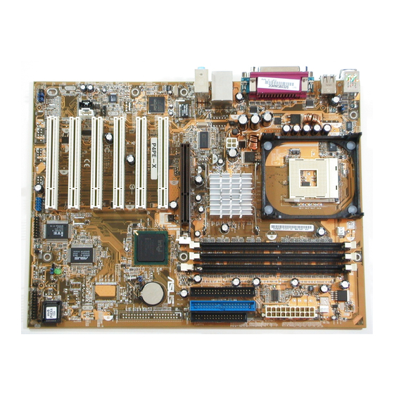
Page 17: Motherboard Layout
® PCI1 Intel I/O CR2032 3V Controller P4PE-X/TE Lithium Cell CMOS Power PCI2 (ICH4) CLRTC PCI3 AD1888 PCI4 SPDIF1 ASUS ASIC AUX1 with Hardware PCI5 Monitor SB_PWR1 2Mbit Firmware PCI6 CHASSIS1 USB_56 FP_AUDIO1 PANEL1 GAME1 ASUS P4PE-X/TE motherboard user guide... -
Page 18: Before You Proceed
Before you proceed Take note of the following precautions before you install motherboard components or change any motherboard settings. 1. Unplug the power cord from the wall socket before touching any component. 2. Use a grounded wrist strap or touch a safely grounded object or to a metal object, such as the power supply case, before handling components to avoid damaging them due to static electricity. -
Page 19: Placement Direction
Place seven (7) screws into the holes indicated by circles to secure the motherboard to the chassis. Do not overtighten the screws! Doing so may damage the motherboard. Place this side towards the rear of the chassis ASUS P4PE-X/TE motherboard user guide... -
Page 20: Central Processing Unit (Cpu)
Central Processing Unit (CPU) 1.8.1 Overview The motherboard comes with a surface mount 478-pin Zero Insertion Force (ZIF) ® ® socket. The socket is designed for the Intel Pentium 4 Processor in the 478-pin package with 512KB L2 cache on 0.13 micron process. This processor supports 800*/533/400MHz front side bus (FSB), and allows data transfer rates of 6.4GB/s, 4.2GB/s, and 3.2GB/s, respectively. -
Page 21: Installing The Cpu
6. Install a CPU heatsink and fan following the instructions that came with the heatsink package. 7. Connect the CPU fan cable to the CPU_FAN1 connector on the motherboard. ASUS P4PE-X/TE motherboard user guide 1-11... -
Page 22: System Memory
System memory The motherboard comes with three Double Data Rate (DDR) Dual Inline Memory Module (DIMM) sockets. These sockets support up to 2GB system memory using 184-pin unbuffered non-ECC PC3200*/2700/2100/1600 DDR DIMMs. The following figure illustrates the location of the DDR DIMM sockets. (* Overclocking mode If you wish to use a PC3200 (400MHz) DDR module, you need to install a CPU... -
Page 23: Installing A Dimm
Hynix HY5DU56822BT-D43 Hynix HYMD232646B8J-D43 AA Obtain DDR DIMMs only from ASUS qualified vendors to ensure system stability. Visit the ASUS website (www.asus.com) for the latest qualified vendors list (QVL). 1.9.2 Installing a DIMM Make sure to unplug the power supply before adding or removing DIMMs or other system components. -
Page 24: Expansion Slots
1.10 Expansion slots The motherboard has six PCI slots and one Accelerated Graphics Port (AGP) slot. To install and configure an expansion card: 1. Install an expansion card following the instructions that came with the chassis. NOTE: The AGP slot supports only 1.5V AGP cards. 2. -
Page 25: Jumpers
You do not need to clear the RTC when the system hangs due to overclocking. For system failure due to overclocking, use the C.P.R. (CPU Parameter Recall) feature. Shut down and reboot the system so BIOS can automatically reset parameter settings to default values. ASUS P4PE-X/TE motherboard user guide 1-15... -
Page 26: Connectors
3. USB device wake-up (3-pin USBPW12, USBPW34, USBPW56) Set these jumpers to +5V to wake up the computer from S1 sleep mode (CPU stopped, DRAM refreshed, system running in low power mode) using the connected USB devices. Set to +5VSB to wake up from S3 sleep mode (no power to CPU, DRAM in slow refresh, power supply in reduced power mode). - Page 27 (Pin 5 is removed to prevent incorrect insertion when using ribbon cables with pin 5 plug). FLOPPY1 NOTE: Orient the red markings on the floppy ribbon cable to PIN 1. ® P4PE-X/TE PIN 1 P4PE-X/TE Floppy Disk Drive Connector ASUS P4PE-X/TE motherboard user guide 1-17...
- Page 28 4. IDE connectors (40-1 pin PRI_IDE, SEC_IDE) This connector supports the provided UltraDMA/100/66 IDE hard disk ribbon cable. Connect the cable’s blue connector to the primary (recommended) or secondary IDE connector, then connect the gray connector to the UltraDMA/100/66 slave device (hard disk drive) and the black connector to the UltraDMA/100/66 master device.
- Page 29 These connectors allow you to receive stereo audio input from sound sources such as a CD-ROM, TV tuner, or MPEG card. CD1(Black) AUX1 (White) ® Left Audio Channel P4PE-X/TE Ground Ground Right Audio Channel P4PE-X/TE Internal Audio Connectors ASUS P4PE-X/TE motherboard user guide 1-19...
- Page 30 8. CPU and chassis fan connectors (3-pin CPU_FAN1, CHA_FAN1) The fan connectors support cooling fans of 350mA~740mA (8.88W max.) or a total of 1A~2.22A (26.64W max.) at +12V. Connect the fan cables to the fan connectors on the motherboard, making sure that the black wire of each cable matches the ground pin of the connector.
- Page 31 GAME/MIDI cable to this connector. The GAME/MIDI port on the module connects a joystick or a game pad for playing games, and MIDI devices for playing or editing audio files. The USB2.0/GAME module is purchased separately. GAME1 ® P4PE-X/TE P4PE-X/TE Game Connector ASUS P4PE-X/TE motherboard user guide 1-21...
-
Page 32: System Panel Connector
12. System panel connector (20-pin PANEL1) This connector accommodates several system front panel functions. Speaker Keyboard Lock Connector Power LED ® P4PE-X/TE Reset SW ATX Power SMI Lead Switch* Requires an ATX power supply. P4PE-X/TE System Panel Connectors • System Power LED Lead (3-1 pin PLED) This 3-1 pin connector connects to the system power LED. -
Page 33: Chapter 2: Bios Information
Chapter 2 This chapter tells how to change system settings through the BIOS Setup menus. Detailed descriptions of the BIOS parameters are also provided. BIOS information... -
Page 34: Managing And Updating Your Bios
BIOS later. 2.1.1 Using ASUS EZ Flash to update the BIOS The ASUS EZ Flash feature allows you to easily update the BIOS without having to go through the long process of booting from a diskette and using a DOS-based utility. - Page 35 5. At the prompt, “Please Enter File Name for NEW BIOS: _”, type in the BIOS file name that you downloaded from the ASUS website, then press <Enter>. EZ Flash will automatically access drive A to look for the file name that you typed.
-
Page 36: Using Aflash To Update The Bios
2.1.2 Using AFLASH to update the BIOS Creating a bootable disk AFLASH.EXE is a Flash Memory Writer utility that updates the BIOS by uploading a new BIOS file to the programmable flash ROM on the motherboard. This file works only in DOS mode. To determine the BIOS version of your motherboard, check the last four numbers of the code displayed on the upper left-hand corner of your screen during bootup. -
Page 37: Updating The Bios
BIOS revision will solve your problems. Careless updating may result to more problems with the motherboard! 1. Download an updated ASUS BIOS file from the Internet (WWW or FTP) (see ASUS contact information on page viii for details) and save to the boot floppy disk you created earlier. - Page 38 BIOS file you saved to the boot disk. If the Flash Memory Writer utility is not able to successfully update a complete BIOS file, the system may not boot. If this happens, call the ASUS service center for support.
-
Page 39: Recovering The Bios With Crashfree Bios 2
4. When the BIOS update process is complete, reboot the system. The recovered BIOS may not be the latest BIOS version for this motherboard. Visit the ASUS website (www.asus.com) to download the latest BIOS file. ASUS P4PE-X/TE motherboard user guide... -
Page 40: Bios Beep Codes
2.1.4 BIOS beep codes When you turn the power on and the system runs POST (Power On Self Tests), you will hear BIOS beeps. Refer to the following table for the meaning of the beeps. Award BIOS Beep Codes Beep Meaning One short beep when No error during POST... -
Page 41: Bios Setup Program
Use this menu to exit the current menu or to exit the Setup program. To access the menu bar items, press the right or left arrow key on the keyboard until the desired item is highlighted. ASUS P4PE-X/TE motherboard user guide... -
Page 42: Legend Bar
2.2.2 Legend bar At the bottom of the Setup screen is a legend bar. The keys in the legend bar allow you to navigate through the various setup menus. The following table lists the keys found in the legend bar with their corresponding functions. Navigation Key(s) Function Description <F1>... -
Page 43: Main Menu
Valid values for month, day, and year are Month: (1 to 12), Day: (1 to 31), Year: (up to 2099). Use the <Tab> or <Shift> + <Tab> keys to move between the month, day, and year fields. ASUS P4PE-X/TE motherboard user guide 2-11... - Page 44 Legacy Diskette A [1.44M, 3.5 in.] Sets the type of floppy drive installed. Configuration options: [None] [360K, 5.25 in.] [1.2M , 5.25 in.] [720K , 3.5 in.] [1.44M, 3.5 in.] [2.88M, 3.5 in.] Floppy 3 Mode Support [Disabled] This is required to support older Japanese floppy drives. The Floppy 3 Mode feature allows reading and writing of 1.2MB (as opposed to 1.44MB) on a 3.5-inch diskette.
-
Page 45: Primary And Secondary Master/Slave
[User Type HDD] Manually enter the number of cylinders, heads and sectors per track for the drive. Refer to the drive documentation or on the drive label for this information. ASUS P4PE-X/TE motherboard user guide 2-13... - Page 46 After entering the IDE hard disk drive information into BIOS, use a disk utility, such as FDISK, to partition and format new IDE hard disk drives. This is necessary so that you can write or read data from the hard disk. Make sure to set the partition of the Primary IDE hard disk drives to active.
-
Page 47: Keyboard Features
IDE devices. Set to [Disabled] to suppress Ultra DMA capability. To make changes to this field, set the Type field to [User Type HDD]. Configuration options: [0] [1] [2] [3] [4] [5] [Disabled] 2.3.2 Keyboard Features ASUS P4PE-X/TE motherboard user guide 2-15... -
Page 48: Advanced Menu
Boot Up NumLock Status [On] This field enables users to activate the Number Lock function upon system boot. Configuration options: [Off] [On] Keyboard Auto-Repeat Rate [12/Sec] This controls the speed at which the system registers repeated keystrokes. Options range from 6 to 30 characters per second. Configuration options: [6/Sec] [8/Sec] [10/Sec] [12/Sec] [15/Sec] [20/Sec] [24/Sec] [30/Sec] Keyboard Auto-Repeat Delay [1/4 Sec] This field sets the time interval for displaying the first and second characters. - Page 49 This item allows you to enable or disable the processor Hyper-Threading Technology. Configuration options: [Disabled] [Enabled] The item Hyper-Threading Technology appears only if you installed an Intel Pentium 4 CPU that supports this feature. ASUS P4PE-X/TE motherboard user guide 2-17...
- Page 50 CPU Level 1 Cache, CPU Level 2 Cache [Enabled] These fields allow you to choose from the default [Enabled] or choose [Disabled] to turn on or off the CPU Level 1 and Level 2 built-in cache. Configuration options: [Disabled] [Enabled] BIOS Update [Enabled] This field functions as an update loader integrated into the BIOS to supply the processor with the required data.
-
Page 51: Chip Configuration
SDRAM. Configuration options: [3T] [2T] SDRAM Active Precharge Delay (value depends on SDRAM SPD) This item controls the number of DDR SDRAM clocks used for DDR SDRAM parameters. Configuration options: [8T] [7T] [6T] [5T] ASUS P4PE-X/TE motherboard user guide 2-19... - Page 52 System Performance Mode [Auto] This item allows you to enhance system performance when set to Turbo mode. If you encounter any problems with the Turbo setting, set to Optimal or Auto. Configuration options: [Auto] [Optimal] [Turbo] SDRAM Idle Timer [Auto] Configuration options: [Infinite] [0T] [8T] [16T] [64T] [Auto] SDRAM Burst Length [Auto] Configuration options: [Auto] [4] [8]...
-
Page 53: I/O Device Configuration
This field allows you to set the address of the onboard parallel port connector. If you disable this field, the Parallel Port Mode and ECP DMA Select configurations are not available. Configuration options: [Disabled] [378H/IRQ7] [278H/IRQ5] ASUS P4PE-X/TE motherboard user guide 2-21... -
Page 54: Pci Configuration
Parallel Port Mode [ECP+EPP] This field allows you to set the operation mode of the parallel port. [Normal] allows normal-speed operation but in one direction only; [EPP] allows bidirectional parallel port operation; [ECP] allows the parallel port to operate in bidirectional DMA mode; [ECP+EPP] allows normal speed operation in a two-way mode. - Page 55 Configuration options: [Disabled] [Enabled] Onboard LAN Boot ROM [Disabled] (appears on LAN models only) This field allows you to enable or disable the option ROM in the onboard LAN controller chipset. Configuration options: [Disabled] [Enabled] ASUS P4PE-X/TE motherboard user guide 2-23...
-
Page 56: Power Menu
PCI IRQ Resource Exclusion IRQ XX Reserved [No/ICU] These fields indicate whether or not the displayed IRQ for each field is being used by a legacy (non-PnP) ISA card. The setting [No/ICU] for an IRQ field indicates that you are using the ISA Configuration Utility (ICU), and that this particular IRQ is NOT required by a legacy ISA card. - Page 57 This field allows you to enable or disable the ACPI Suspend-to-RAM feature. To support this feature, the +5VSB of the power supply should have the capacity to provide more than 720mA current. Configuration options: [Disabled] [Enabled] ASUS P4PE-X/TE motherboard user guide 2-25...
-
Page 58: Power Up Control
Suspend Mode [Disabled] Sets the time period before the system goes into suspend mode. Configuration options: [Disabled] [1~2 Min] [2~3 Min] [4~5 min] [8~9 Min] [20 Min] [30 Min] [40 Min] [1 hour] PWR Button < 4 Secs [Soft Off] When set to [Soft off], the ATX switch can be used as a normal system power-off button when pressed for less than 4 seconds. - Page 59 This allows an unattended or automatic system power up. You may configure your system to power up at a certain time of the day by selecting [Everyday] or at a certain time and day by selecting [By Date]. Configuration options: [Disabled] [Everyday] [By Date] ASUS P4PE-X/TE motherboard user guide 2-27...
-
Page 60: Hardware Monitor
2.5.2 Hardware Monitor MB Temperature [xxxC/xxxF] CPU Temperature [xxxC/xxxF] The onboard hardware monitor automatically detects and displays the motherboard and CPU temperatures. CPU Fan Speed [xxxxRPM] or [N/A] Chassis Fan Speed [xxxxRPM] or [N/A] The onboard hardware monitor automatically detects and displays the CPU and chassis fan speeds in rotations per minute (RPM). -
Page 61: Boot Menu
PCI bus slots instead of using the BIOS. When [Yes] is selected, interrupts may be reassigned by the OS. If you installed a non-PnP OS or if you want to prevent reassigning of interrupt settings, keep the default setting [No]. Configuration options: [No] [Yes] ASUS P4PE-X/TE motherboard user guide 2-29... - Page 62 Reset Configuration Data [No] The Extended System Configuration Data (ESCD) contain information about non- PnP devices. It also holds the complete record of how the system was configured the last time it was booted. Select [Yes] if you want to clear these data during the Power-On-Self-Test (POST).
-
Page 63: Exit Menu
This option saves your selections without exiting the Setup program. You can then return to other menus and make further changes. After you select this option, a confirmation window appears. Select [Yes] to save changes to the non-volatile RAM. ASUS P4PE-X/TE motherboard user guide 2-31... - Page 64 2-32 Chapter 2: BIOS information...
-
Page 65: Chapter 3: Software Support
Chapter 3 This chapter describes the contents of the support CD that comes with the motherboard package. Software support... -
Page 66: Install An Operating System
The contents of the support CD are subject to change at any time without notice. Visit the ASUS website for updates. 3.2.1 Running the support CD To begin using the support CD, simply insert the CD into your CD-ROM drive. The CD automatically displays the Drivers menu if Autorun is enabled in your computer. -
Page 67: Drivers Menu
6-channel audio features. USB 2.0 Driver This item installs the USB 2.0 driver to support your USB devices. Realtek RTL8001C 10/100M LAN Drivers ® This item installs the Realtek RTL8001C drivers to support 10BASE-T/100BASE- TX networking. ASUS P4PE-X/TE motherboard user guide... -
Page 68: Utilities Menu
Install ASUS Update This program allows you to download the latest version of the BIOS from the ASUS website. Before using the ASUS Update, make sure that you have an Internet connection so you can connect to the ASUS website. -
Page 69: Asus Contact Information
3.2.4 ASUS Contact Information Clicking the ASUS Contact Information tab displays as stated. You may also find this information on page viii of this user guide. ASUS P4PE-X/TE motherboard user guide... - Page 70 Chapter 3: Software support...
Need help?
Do you have a question about the P4PE-X TE and is the answer not in the manual?
Questions and answers