Table of Contents
Advertisement
Advertisement
Table of Contents

Related Manuals for Asus P4P800S-X


Summary of Contents for Asus P4P800S-X
- Page 1 P4P800S-X User Guide...
- Page 2 Product warranty or service will not be extended if: (1) the product is repaired, modified or altered, unless such repair, modification of alteration is authorized in writing by ASUS; or (2) the serial number of the product is defaced or missing.
-
Page 3: Table Of Contents
Safety information ... vii About this guide ... viii Conventions used in this guide ... viii Where to find more information ... viii P4P800S-X specification summary ... ix Chapter 1: Product introduction 1.1 Welcome! ... 1-2 1.2 Package contents ... 1-2 1.3 Special features ... - Page 4 Using AFUDOS to update the BIOS ... 2-3 2.1.3 Using AFUDOS to copy BIOS from PC ... 2-4 2.1.4 Using ASUS EZ Flash to update the BIOS ... 2-5 2.1.5 Recovering the BIOS with CrashFree BIOS 2 ... 2-6 2.2 BIOS Setup program ... 2-8 2.2.1...
- Page 5 Chapter 3: Software support 3.1 Install an operating system ... 3-2 3.2 Support CD information ... 3-2 3.2.1 Running the support CD ... 3-2 3.2.2 Drivers menu ... 3-3 3.2.3 Utilities menu ... 3-3 3.2.4 ASUS Contact Information ... 3-4...
-
Page 6: Federal Communications Commission Statement
Notices Federal Communications Commission Statement This device complies with Part 15 of the FCC Rules. Operation is subject to the following two conditions: • This device may not cause harmful interference, and • This device must accept any interference received including interference that may cause undesired operation. -
Page 7: Electrical Safety
Safety information Electrical safety • To prevent electrical shock hazard, disconnect the power cable from the electrical outlet before relocating the system. • When adding or removing devices to or from the system, ensure that the power cables for the devices are unplugged before the signal cables are connected. -
Page 8: About This Guide
1. ASUS Websites The ASUS websites worldwide provide updated information on ASUS hardware and software products. The ASUS websites are listed in the ASUS Contact Information on the inside front cover. 2. Optional Documentation Your product package may include optional documentation, such as warranty flyers, that may have been added by your dealer. -
Page 9: P4P800S-X Specification Summary
Adjustable CPU, Memory and AGP voltage SFS (Stepless Frequency Selection) from 100MHz to 266MHz at 1Mhz increment Adjustable FSB/DDR ratio. Fixed AGP/PCI frequencies ASUS C.P.R. (CPU Parameter Recall) Rear panel I/O 1 x Parallel port 1 x Serial port 1 x PS/2 keyboard port 1 x PS/2 mouse port 4 x USB 2.0 ports... - Page 10 20-pin panel connector Front panel audio connector 3Mb Flash ROM, AMI BIOS, ACPI, PnP, DMI2.0, WfM 2.0, SM BIOS 2.3, DMI 2.0, ASUS CrashFree BIOS 2, ASUS EZ Flash, ASUS MyLogo PCI 2.2, USB 2.0/1.1 DMI 2.0, WOL/WOR by PME, SMBus ATX power supply (with 4-pin 12V plug) ATX form factor: 12 in x 7.0 in (30.5 cm x 17 cm)
-
Page 11: Chapter 1: Product Introduction
Chapter 1 This chapter describes the features of the P4P800S-X motherboard. It includes brief descriptions of the motherboard components, and illustrations of the layout, jumper settings, and connectors. Product introduction... -
Page 12: Welcome
The ASUS P4P800S-X motherboard, based on the Intel supporting 800FSB that delivers a host of new features and latest technologies making it another standout in the long line of ASUS quality motherboards! Before you start installing the motherboard, and hardware devices on it, check the items in your package with the list below. -
Page 13: Asus Mylogo
Interface (S/PDIF) jack located at the rear panel I/O. See pages 1-17, 3-3. ASUS MyLogo™ This feature present in the motherboard allows you to personalize and add style to your system with customizable boot logos. See pages 2-29. ASUS P4P800S-X motherboard... -
Page 14: Before You Proceed
The illustration below shows the location of the onboard LED. P4P800S-X ® P4P800S-X Onboard LED SB_PWR Standby Powered Power Chapter 1: Product introduction... -
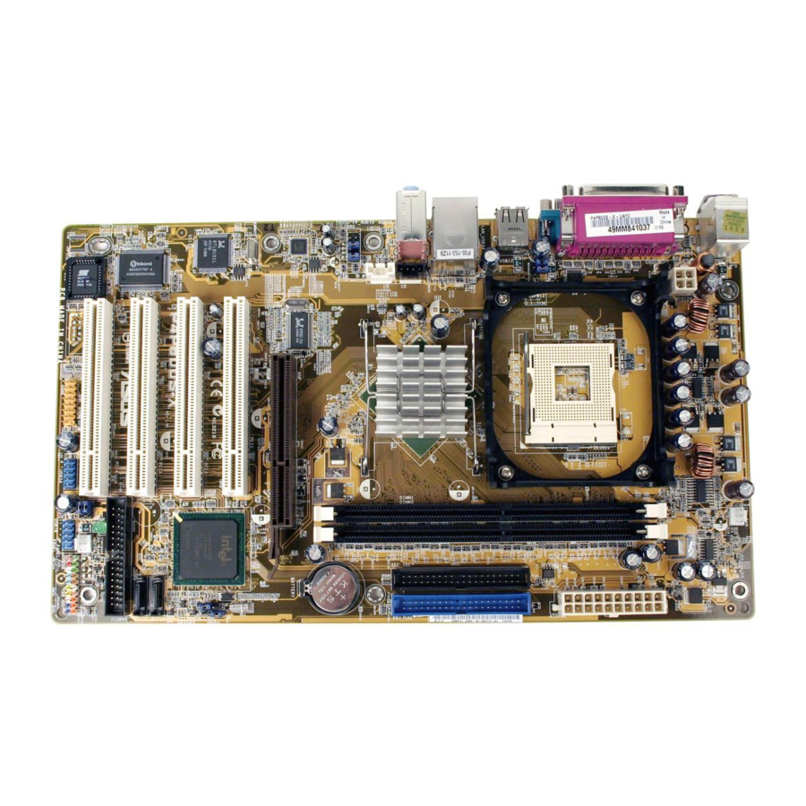
Page 15: Motherboard Overview
Top: USB3 RJ-45 USB4 Top:Line In Center:Line Out Below:Mic In FP_AUDIO AD1888 RTL8101L USBPW1 USBPW2 +5VSB (Default) (Default) ASUS P4P800S-X motherboard 18.2cm( 7.2in) Intel 82848 Accelerated Graphics Port (AGP) PCI1 PCI2 P4P800S-X PCI3 ® PCI4 USBPW3 USBPW4 GAME USB56 USBPW3... -
Page 16: Placement Direction
1.5.2 Placement direction When installing the motherboard, make sure that you place it into the chassis in the correct orientation. The edge with external ports goes to the rear part of the chassis as indicated in the image below. 1.5.3 Screw holes Place seven (7) screws into the holes indicated by circles to secure the motherboard to the chassis. -
Page 17: Central Processing Unit (Cpu)
This mark indicates the processor Pin 1 that should match a specific corner of the CPU socket. P4P800S-X ® P4P800S-X Socket 478 Incorrect installation of the CPU into the socket may bend the pins and severely damage the CPU! ®... -
Page 18: Installing The Cpu
1.6.2 Installing the CPU Follow these steps to install a CPU. 1. Locate the 478-pin ZIF socket on the motherboard. 2. Unlock the socket by pressing the lever sideways, then lift it up to a 90°- 100° angle. Make sure that the socket lever is lifted up to 90°-100°... -
Page 19: System Memory
The following figure illustrates the location of the DDR DIMM sockets. P4P800S-X ® P4P800S-X 184-Pin DDR DIMM Sockets 1. Make sure to unplug the power supply before adding or removing DIMMs or other system components. Failure to do so may cause severe damage to both the motherboard and the components. -
Page 20: Memory Frequency
Table 1 Memory frequency/CPU FSB synchronization This motherboard supports different memory frequencies depending on the CPU FSB (Front Side Bus) and the type of DDR DIMM. CPU FSB 800 MHz 533 MHz 400 MHz *When using 800 MHz FSB CPU, PC2700 DDR DIMMs run only at 320MHz (not 333MHz) due to chipset limitation. - Page 21 VT400FMV/2561103 512MB Veritech VT400FMV/5121003 256MB MD44256VIT3208GMHA01 512MB MD44512VIT3208GATA03 Legend: SS - Single-Sided Obtain DDR DIMMs only from ASUS qualified vendors. Visit the ASUS website (www.asus.com) for the latest QVL. ASUS P4P800S-X motherboard Model Brand SS/DS SAMSUNG SAMSUNG SAMSUNG SAMSUNG SAMSUNG...
-
Page 22: Installing A Dimm
1.7.3 Installing a DIMM Follow these steps to install a DIMM. 1. Unlock a DIMM socket by pressing the retaining clips outward. 2. Align a DIMM on the socket such that the notch on the DIMM matches the break on the socket. -
Page 23: Expansion Slots
When using PCI cards on shared slots, ensure that the drivers support “Share IRQ” or that the cards do not need IRQ assignments. Otherwise, conflicts will arise between the two PCI groups, making the system unstable and the card inoperable. ASUS P4P800S-X motherboard Standard Function System Timer Keyboard Controller... -
Page 24: Pci Slots
Install only +1.5V AGP cards. P4P800S-X ® P4P800S-X Accelerated Graphics Port (AGP) If installing the ATi 9500 or 9700 Pro Series VGA cards, use only the card version PN xxx-xxxxx-30 or later, for optimum performance and overclocking stability. -
Page 25: Clear Rtc Ram (Clrtc1)
Removing the cap will cause system boot failure! P4P800S-X ® P4P800S-X Clear RTC RAM You do not need to clear the RTC when the system hangs due to overclocking. For system failure due to overclocking, use the C.P.R. (CPU Parameter Recall) feature. - Page 26 (+5VSB) whether under normal condition or in sleep mode. 3. The rear panel USB ports (Ports 1 to 4) do not support device wake-up from S4 sleep mode. P4P800S-X ® P4P800S-X USB Device Wake Up 1-16 USBPW1 USBPW2 +5VSB (Default)
-
Page 27: Connectors
9. Serial connector. This 9-pin COM1 port is for serial devices. 10. S/PDIF out jack. This jack connects to external audio output devices. 11. PS/2 keyboard port. This purple connector is for a PS/2 keyboard. ASUS P4P800S-X motherboard 4-Speaker 6-Speaker... -
Page 28: Internal Connectors
(Pin 5 is removed to prevent incorrect insertion when using ribbon cables with pin 5 plug). P4P800S-X ® P4P800S-X Floppy Disk Drive Connector 1-18 NOTE: Orient the red markings (usually zigzag) on the IDE ribbon cable to PIN 1. - Page 29 P4P800S-X ® P4P800S-X ATX Power Connectors 4. Internal audio connectors (4-pin CD1, AUX1) These connectors allow you to receive stereo audio input from sound sources such as a CD-ROM, TV tuner, or MPEG card.
- Page 30 DO NOT place jumper caps on the fan connectors! P4P800S-X ® P4P800S-X 12-Volt Fan Connectors 6. USB header (10-1 pin USB56, USB78) If the USB ports on the rear panel are inadequate, a USB header is available for additional USB ports.
- Page 31 P4P800S-X ® P4P800S-X Front Panel Audio Connector 8. Chassis intrusion connector (4-1 pin CHASSIS1) This lead is for a chassis designed with intrusion detection feature. This requires an external detection mechanism such as a chassis intrusion sensor or microswitch.
- Page 32 MIDI devices for playing or editing audio files. P4P800S-X ® P4P800S-X Game Connector The GAME/MIDI module is purchased separately. 10. Serial ATA connectors (7-pin SATA1, SATA2) These next generation connectors support the thin Serial ATA cables for primary internal storage devices.
- Page 33 11. System panel connector (10-1 pin PANEL1) This connector accommodates several system front panel functions. P4P800S-X ® P4P800S-X System Panel Connector • System Power LED Lead (Green 3-pin PLED) This 3-pin connector connects to the system power LED. The LED lights up when you turn on the system power, and blinks when the system is in sleep mode.
- Page 34 1-24 Chapter 1: Product introduction...
-
Page 35: Bios Information
Chapter 2 This chapter tells how to change system settings through the BIOS Setup menus. Detailed descriptions of the BIOS parameters are also provided. BIOS information... -
Page 36: Chapter 2: Bios Information
2. ASUS EZ Flash - Updates the BIOS using a floppy disk during POST. 3. ASUS CrashFree BIOS 2 - Updates the BIOS using a bootable floppy disk or the motherboard support CD. Refer to the corresponding sections for details on these utilities. -
Page 37: Using Afudos To Update The Bios
2.1.2 Using AFUDOS to update the BIOS To update the BIOS using the AFUDOS.EXE utility: 1. Visit the ASUS website (www.asus.com) to download the latest BIOS file for your motherboard. Save the BIOS file to a bootable floppy disk. Write the BIOS file name on a piece of paper. You need to type the exact BIOS file name at the prompt. -
Page 38: Using Afudos To Copy Bios From Pc
When the BIOS update process is complete, the utility returns to the DOS prompt. A:\>afudos /iP4P800SX.ROM AMI Firmware Update Utility - Version 1.10 Copyright (C) 2002 American Megatrends, Inc. All rights reserved. Reading file ... done Erasing flash ... done Writing flash ... -
Page 39: Using Asus Ez Flash To Update The Bios
When the copy process is complete, the utility returns to the DOS prompt. 2.1.4 Using ASUS EZ Flash to update the BIOS The ASUS EZ Flash feature allows you to easily update the BIOS without having to go through the long process of booting from a diskette and using a DOS-based utility. -
Page 40: Recovering The Bios With Crashfree Bios 2
DO NOT shutdown or reset the system while updating the BIOS! Doing so may cause system boot failure! User recovery requested. Starting BIOS recovery... Checking for floppy... Floppy found! Reading file “P4P800SX.ROM”. Completed. Start flashing... Flashed successfully. Rebooting. 2.1.5 Recovering the BIOS with CrashFree BIOS 2 The CrashFree BIOS 2 auto recovery tool allows you to restore BIOS from the motherboard support CD, or from a floppy disk that contains the BIOS file, in case the current BIOS on the motherboard fails or gets corrupted. - Page 41 2. When the BIOS update process is complete, reboot the system. The recovered BIOS may not be the latest BIOS version for this motherboard. Visit ASUS website (www.asus.com) to download the latest BIOS file. ASUS P4P800S-X motherboard...
-
Page 42: Bios Setup Program
The BIOS setup screens shown in this chapter are for reference purposes only, and may not exactly match what you see on your screen. Visit the ASUS website (www.asus.com) to download the latest product and BIOS information. Chapter 2: BIOS information... -
Page 43: Bios Menu Screen
At the bottom right corner of a menu screen are the navigation keys for that particular menu. Use the navigation keys to select items in the menu and change the settings. Some of the navigation keys differ from one screen to another. ASUS P4P800S-X motherboard Configuration fields [11:10:19] [Thu 03/27/2003] [1.44M, 3.5 in]... -
Page 44: Menu Items
[1.44M, 3.5 in] select a field. Use [+] or [-] to Primary IDE Master :[ST320413A] configure system time. Primary IDE Slave :[ASUS CD-S340] Secondary IDE Master :[Not Detected] Secondary IDE Slave :[Not Detected] Third IDE Master :[Not Detected] Fourth IDE Master... -
Page 45: Main Menu
2.3.3 Legacy Diskette A [1.44M, 3.5 in.] Sets the type of floppy drive installed. Configuration options: [Disabled] [360K, 5.25 in.] [1.2M , 5.25 in.] [720K , 3.5 in.] [1.44M, 3.5 in.] [2.88M, 3.5 in.] ASUS P4P800S-X motherboard [11:51:19] Use [ENTER], [TAB]... -
Page 46: Primary And Secondary Ide Master/Slave; Third And Fourth Ide Master
2.3.4 Primary and Secondary IDE Master/Slave; Third and Fourth IDE Master While entering Setup, BIOS auto-detects the presence of IDE devices. There is a separate sub-menu for each IDE device. Select a device item then press Enter to display the IDE device information. Primary IDE Master Device : Hard Disk... -
Page 47: Ide Configuration
(OS) that you installed. Set to Enhanced Mode if you are using native OS, such as Windows 2000/XP. Set to Compatible Mode if you are using legacy OS including MS-DOS, Linux, Windows ME/98/NT4.0. Configuration options: [Compatible Mode] [Enhanced Mode] ASUS P4P800S-X motherboard [Enhanced Mode] [S-ATA] [35]... -
Page 48: System Information
Enhanced Mode Support On [S-ATA] The default setting S-ATA allows you to use native OS (Windows 2000/XP) on Serial ATA and Parallel ATA ports. We recommend that you do not change the default setting for better OS compatibility. In this setting, you may use legacy OS (Windows ME/98/98SE/NT4.0) on the Parallel ATA ports only if you did not install any Serial ATA device. -
Page 49: Advanced Menu
Configuration options: [Manual] [Standard] [Overclock 5%] [Overclock 10%] [Overclock 20%] [Overclock 30%] Selecting a very high CPU frequency may cause the system to become unstable! If this happens, revert to the default setting. ASUS P4P800S-X motherboard Adjust system frequency/voltage [Standard]... -
Page 50: Dram Frequency [Auto]
CPU VCore Voltage [Auto] Allows you to select a specific CPU VCore voltage. The configurations depends on the type of CPU installed. Refer to the CPU documentation before setting the CPU VCore voltage. A very high Vcore voltage may severely damage the CPU! When you set the AI Overclocking Tuner item to [Manual], the related overclocking items appear. -
Page 51: Cpu Configuration
This item allows you to enable or disable the processor Hyper-Threading Technology. Configuration options: [Disabled] [Enabled] The item Hyper-Threading Technology appears only if you installed an Intel Pentium 4 CPU that supports this feature. See page1-7 for details. ASUS P4P800S-X motherboard 2-17... -
Page 52: Chipset
2.4.3 Chipset The Chipset menu items allow you to change the advanced chipset settings. Select an item then press Enter to display the sub-menu. Advanced Chipset Settings Warning: Setting wrong values in below sections may cause system to malfunction. Configure DRAM Timing by SPD Memory Acceleration Mode DRAM Idle Timer DRAM Refresh Rate... - Page 53 Configuration options: [4MB] [8MB] [16MB] [32MB] [64MB] [128MB] [256MB] Spread Spectrum [Enabled] This field enables or disables the clock generator spread spectrum. Configuration options: [Disabled] [Enabled] ICH Delayed Transaction [Enabled] Configuration options: [Disabled] [Enabled] MPS Revision [1.4] Configuration options: [1.1] [1.4] ASUS P4P800S-X motherboard 2-19...
-
Page 54: Onboard Devices Configuration
2.4.4 Onboard Devices Configuration Onboard AC’97 Audio Onboard LAN Onboard LAN Boot ROM Serial Port1 Address Parallel Port Address OnBoard Game/MIDI Port OnBoard AC’97 Audio [Auto] [Auto] allows the BIOS to detect whether you are using any audio device. If an audio device is detected, the onboard audio controller is enabled;... -
Page 55: Pci Pnp
ISA graphics device is installed in the system so that the latter can function correctly. Setting to [Disabled] deactivates this feature. Configuration options: [Disabled] [Enabled] ASUS P4P800S-X Motherboard NO: Lets the BIOS configure all the devices in the system. -
Page 56: Usb Configuration
PCI IDE BusMaster [Enabled] Allows BIOS to use PCI bus mastering when reading/writing to IDE devices. Configuration options: [Disabled] [Enabled] IRQ xx [Available] When set to [Available], the specific IRQ is free for use of PCI/PnP devices. When set to [Reserved], the IRQ is reserved for legacy ISA devices. Configuration options: [Available] [Reserved] 2.4.6 USB Configuration The items in this menu allows you to change the USB-related features. -
Page 57: Usb Mass Storage Device Configuration
The message “No USB mass storage device detected” appears if none is installed in the system. Configuration options: [10 Sec ] [20 Sec] [30 Sec] [40 Sec] ASUS P4P800S-X Motherboard [20 Sec] 2-23... -
Page 58: Power Menu
Power menu The Power menu items allow you to change the settings for the Advanced Power Management (APM) feature. Select an item then press <Enter> to display the configuration options. Suspend Mode Repost Video on S3 Resume ACPI 2.0 Support ACPI APIC Support BIOS-->AML ACPI table APM Configuration... -
Page 59: Advanced Power Management Configuration
Configuration options: [87.5%] [75.0%] [62.5%] [50%] [37.5%] [25%] [12.5%] Power Button Mode [On/Off] Allows the system to go into On/Off mode or suspend mode when the power button is pressed. Configuration options: [On/Off] [Suspend] ASUS P4P800S-X motherboard [Enabled] [Disabled] [Disabled]... - Page 60 Restore on AC Power Loss [Power Off] When set to Power Off, the system goes into off state after an AC power loss. When set to Power On, the system goes on after an AC power loss. When set to Last State, the system goes into either off or on state whatever was the system state before the AC power loss.
-
Page 61: Hardware Monitor
If any of the monitored items is out of range, the following error message appears: “Hardware Monitor found an error. Enter Power setup menu for details”. You will then be prompted to “Press F1 to continue or DEL to enter SETUP”. ASUS P4P800S-X motherboard CPU Temperature [40.5ºC/102.5ºF] [33ªC/91ºF]... -
Page 62: Boot Menu
Hit ‘DEL’ Message Display Interrupt 19 Capture 2-28 Specifies the Boot Device Priority sequence. [1st FLOPPY DRIVE] [PM-ST320413A] [SM-ASUS CD-S360] Allows BIOS to skip certain tests while booting. This will [Enabled] decrease the time [Enabled] needed to boot the [Force BIOS] system. - Page 63 This allows you to enable or disable the full screen logo display feature. Configuration options: [Disabled] [Enabled] Make sure that the Full Screen Logo item is set to [Enabled] if you wish to use the ASUS MyLogo™ feature. Add On ROM Display Mode [Force BIOS] Sets the display mode for option ROM.
-
Page 64: Security
2.6.3 Security The Security menu items allow you to change the system security settings. Select an item then press Enter to display the configuration options. Security Settings Supervisor Password User Password Change Supervisor Password Change User Password Clear User Password Boot Sector Virus Protection Change Supervisor Password Select this item to set or change the supervisor password. -
Page 65: Change User Password
When set to [Setup], BIOS checks for user password when accessing the Setup utility. When set to [Always], BIOS checks for user password both when accessing Setup and booting the system. Configuration options: [Setup] [Always] ASUS P4P800S-X motherboard <Enter> to change password. -
Page 66: Boot Sector Virus Protection [Disabled]
Boot Sector Virus Protection [Disabled] Allows you to enable or disable the boot sector virus protection. Configuration options: [Disabled] [Enabled] Exit menu The Exit menu items allow you to load the optimal or failsafe default values for the BIOS items, and save or discard your changes to the BIOS items. Exit Options Exit &... -
Page 67: Chapter 3: Software Support
Chapter 3 This chapter describes the contents of the support CD that comes with the motherboard package. Software support... -
Page 68: Install An Operating System
The contents of the support CD are subject to change at any time without notice. Visit the ASUS website for updates. 3.2.1 Running the support CD To begin using the support CD, simply insert the CD into your CD-ROM drive. The CD automatically displays the Drivers menu if Autorun is enabled in your computer. -
Page 69: Drivers Menu
ASUS PC Probe This smart utility monitors the fan speed, CPU temperature, and system voltages, and alerts you on any detected problems. This utility helps you keep your computer at a healthy operating condition. ASUS P4P800S-X motherboard ® 98SE only. -
Page 70: Asus Contact Information
Install ASUS Update This program allows you to download the latest version of the BIOS from the ASUS website. Before using the ASUS Update, make sure that you have an Internet connection so you can connect to the ASUS website. Installing ASUS Update also installs ASUS Mylogo™.
Need help?
Do you have a question about the P4P800S-X and is the answer not in the manual?
Questions and answers