Table of Contents
Advertisement
Advertisement
Table of Contents

Subscribe to Our Youtube Channel
Related Manuals for Asus P4PE-X


Summary of Contents for Asus P4PE-X
- Page 1 P4PE-X User Guide...
- Page 2 Product warranty or service will not be extended if: (1) the product is repaired, modified or altered, unless such repair, modification of alteration is authorized in writing by ASUS; or (2) the serial number of the product is defaced or missing.
-
Page 3: Table Of Contents
1.12 Connectors ............... 1-16 Chapter 2: BIOS information 2.1 Managing and updating your BIOS ........2-2 2.1.1 Using ASUS EZ Flash to update the BIOS .... 2-2 2.1.2 Using AFLASH to update the BIOS ....... 2-4 2.1.3 CrashFree BIOS feature ........2-7 2.1.4... - Page 4 Chapter 3: Software support 3.1 Install an operating system ..........3-2 3.2 Support CD information ............3-2 3.2.1 Running the support CD ........3-2 3.2.2 Drivers menu ............3-3 3.2.3 Utilities menu ............3-4 3.2.4 ASUS Contact Information ........3-5...
-
Page 5: Notices
Notices Federal Communications Commission Statement This device complies with FCC Rules Part 15. Operation is subject to the following two conditions: • This device may not cause harmful interference, and • This device must accept any interference received including interference that may cause undesired operation. -
Page 6: Safety Information
Safety information Electrical safety • To prevent electrical shock hazard, disconnect the power cable from the electrical outlet before relocating the system. • When adding or removing devices to or from the system, ensure that the power cables for the devices are unplugged before the signal cables are connected. -
Page 7: About This Guide
1. ASUS Websites The ASUS websites worldwide provide updated information on ASUS hardware and software products. The ASUS websites are listed in the ASUS Contact Information on page viii. 2. Optional Documentation Your product package may include optional documentation, such as warranty flyers, that may have been added by your dealer. -
Page 8: Asus Contact Information
Technical Support Support Fax: +1-510-608-4555 General Support: +1-502-933-8713 Web Site: www.asus.com Support Email: tsd@asus.com ASUS COMPUTER GmbH (Germany and Austria) Address: Harkortstr. 25, 40880 Ratingen, BRD, Germany General Email: sales@asuscom.de (for marketing requests only) General Fax: +49-2102-9599-31 Technical Support Support Hotline:... -
Page 9: P4Pe-X Specifications Summary
P4PE-X specifications summary ® ® Socket 478 for Intel Pentium On-die 512KB/256KB L2 cache with full speed ® Intel Hyper-Threading technology ready New power design for up to 3.06 GHz or faster speed Chipset Intel 82845PE MCH Intel 82801DB ICH4... - Page 10 P4PE-X specifications summary BIOS features 2Mb Flash ROM, Award BIOS, TCAV, PnP, DMI2.0, SM BIOS2.3, CrashFree BIOS, ASUS EZ Flash Industry standard PCI 2.2, USB 2.0 Manageability WfM 2.0. DMI 2.0, WOL/WOR by PME, chassis intrusion, SMBus Form Factor ATX form factor: 12 in x 9.0 in (30.5 cm x 22.9 cm)
-
Page 11: Chapter 1: Product Introduction
Chapter 1 This chapter describes the features of the P4PE-X motherboard. It includes brief descriptions of the motherboard components, and illustrations of the layout, jumper settings, and connectors. Product introduction... -
Page 12: Welcome
Supporting up to 2GB of system memory with PC3200/2700/2100/1600 DDR SDRAM, high-resolution graphics via an AGP 4X slot, USB 2.0, and 6-channel audio features, the P4PE-X is your affordable vehicle to enter the world of computing! Before you start installing the motherboard, and hardware devices on it, check the items in your package with the list below. -
Page 13: Special Features
Sony/Philips Digital Interface (S/PDIF) Out module. See page 1-18. ASUS EZ Flash BIOS With the ASUS EZ Flash, you can easily update the system BIOS even before loading the operating system. No need to use a DOS-based utility or boot from a floppy disk. -
Page 14: Motherboard Components
Motherboard components Before you install the motherboard, learn about its major components and available features to facilitate the installation and future upgrades. Refer to the succeeding pages for the component descriptions. Chapter 1: Product introduction... - Page 15 This LED acts as a reminder to turn off the system power before plugging or unplugging devices. ASUS ASIC. This chip performs multiple system functions that include hardware and system voltage monitoring, IRQ routing, among others. Super I/O controller. This Low Pin Count (LPC) interface provides the commonly used Super I/O functionality.
- Page 16 Audio CODEC. The ADI AD1980 is an AC’97 CODEC that allows 6-channel audio playback. The audio CODEC provides six DAC channels for 5.1 surround sound, S/PDIF output, AUX and Line In stereo inputs, integrated headphone amplifier, greater than 90dB dynamic range, and stereo Mic PREAMP support.
-
Page 17: Motherboard Layout
Gbit/Fast CR2032 3V Controller BCM5702/4401 Lithium Cell P4PE-X Ethernet CMOS Power PCI2 (ICH4) CLRTC PCI3 Audio Codec PCI4 SPDIF1 ASUS ASIC AUX1 with Hardware PCI5 Monitor SB_PWR1 4Mbit Firmware PCI6 CHASSIS1 USB_56 FP_AUDIO1 PANEL1 GAME1 ASUS P4PE-X motherboard user guide... -
Page 18: Before You Proceed
® P4PE-X SB_PWR1 Standby Powered P4PE-X Onboard LED Power Chapter 1: Product introduction... -
Page 19: Motherboard Installation
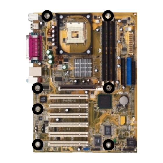
Place seven (7) screws into the holes indicated by circles to secure the motherboard to the chassis. Do not overtighten the screws! Doing so may damage the motherboard. Place this side towards the rear of the chassis ASUS P4PE-X motherboard user guide... -
Page 20: Central Processing Unit (Cpu)
Central Processing Unit (CPU) 1.8.1 Overview The motherboard comes with a surface mount 478-pin Zero Insertion Force (ZIF) socket. The socket is designed for the Intel ® Pentium ® 4 Processor in the 478-pin package with 512KB L2 cache on 0.13 micron process. This processor supports 800*/533/400MHz front side bus (FSB), and allows data transfer rates of 6.4GB/s, 4.2GB/s, and 3.2GB/s, respectively. -
Page 21: Installing The Cpu
6. Install a CPU heatsink and fan following the instructions that came with the heatsink package. 7. Connect the CPU fan cable to the CPU_FAN1 connector on the motherboard. ASUS P4PE-X motherboard user guide 1-11... -
Page 22: System Memory
80 Pins ® P4PE-X 104 Pins P4PE-X 184-Pin DDR DIMM Sockets 1.9.1 Memory configurations You may install any DDR DIMMs with 64MB, 128MB, 256MB, 512MB, and 1GB densities into the DIMM sockets. Use only the following combinations to install DDR DIMMs. Otherwise, the system may not boot up. -
Page 23: Installing A Dimm
333/266 MHz 400 MHz PC2100 266 MHz Obtain DDR DIMMs only from ASUS qualified vendors to ensure system stability. Visit the ASUS website (www.asus.com) for the latest qualified vendors list (QVL). 1.9.2 Installing a DIMM Make sure to unplug the power supply before adding or removing DIMMs or other system components. -
Page 24: Expansion Slots
1.10 Expansion slots The motherboard has six PCI slots and one Accelerated Graphics Port (AGP) slot. To install and configure an expansion card: 1. Install an expansion card following the instructions that came with the chassis. NOTE: The AGP slot supports only 1.5V AGP cards. 2. -
Page 25: Jumpers
You do not need to clear the RTC when the system hangs due to overclocking. For system failure due to overclocking, use the C.P.R. (CPU Parameter Recall) feature. Shut down and reboot the system so BIOS can automatically reset parameter settings to default values. ASUS P4PE-X motherboard user guide 1-15... -
Page 26: Connectors
2-pin plug. P4PE-X IDE_LED1 P4PE-X HD Activity LED 2. Chassis intrusion connector (4-1 pin CHASSIS1) This lead is for a chassis designed with intrusion detection feature. This requires an external detection mechanism such as a chassis intrusion sensor or microswitch. - Page 27 (Pin 5 is removed to prevent incorrect insertion when using ribbon cables with pin 5 plug). FLOPPY1 NOTE: Orient the red markings on the floppy ribbon cable to PIN 1. ® P4PE-X PIN 1 P4PE-X Floppy Disk Drive Connector ASUS P4PE-X motherboard user guide 1-17...
- Page 28 -12.0VDC +3.3VDC +3.3VDC P4PE-X ATX & Auxiliary Power Connectors 6. Digital audio connector (4-1 pin SPDIF1) This connector is for the S/PDIF audio module that allows digital instead of analog sound output. Connect one end of the audio cable to the S/PDIF Out connector on the motherboard, and the other end to the S/PDIF module.
- Page 29 These connectors allow you to receive stereo audio input from sound sources such as a CD-ROM, TV tuner, or MPEG card. CD1(Black) AUX1 (White) ® Left Audio Channel P4PE-X Ground Ground Right Audio Channel P4PE-X Internal Audio Connectors ASUS P4PE-X motherboard user guide 1-19...
- Page 30 ® P4PE-X FP_AUDIO1 P4PE-X Front Panel Audio Connector 10. USB header (10-1 pin USB_56) If the USB ports on the rear panel are inadequate, a USB header is available for additional USB ports. The USB header complies with USB 2.0 specification that supports up to 480 Mbps connection speed.
- Page 31 12. System panel connector (20-pin PANEL1) This connector accommodates several system front panel functions. Keyboard Lock Speaker Connector Power LED ® P4PE-X Reset SW ATX Power SMI Lead Switch* Requires an ATX power supply. P4PE-X System Panel Connectors ASUS P4PE-X motherboard user guide 1-21...
- Page 32 • System Power LED Lead (3-1 pin PLED) This 3-1 pin connector connects to the system power LED. The LED lights up when you turn on the system power, and blinks when the system is in sleep mode. • Keyboard Lock Lead (2-pin KEYLOCK) This 2-pin connector connects to a chassis-mounted switch to allow the use of the keyboard lock feature.
-
Page 33: Chapter 2: Bios Information
Chapter 2 This chapter tells how to change system settings through the BIOS Setup menus. Detailed descriptions of the BIOS parameters are also provided. BIOS information... -
Page 34: Managing And Updating Your Bios
BIOS later. 2.1.1 Using ASUS EZ Flash to update the BIOS The ASUS EZ Flash feature allows you to easily update the BIOS without having to go through the long process of booting from a diskette and using a DOS-based utility. - Page 35 5. At the prompt, “Please Enter File Name for NEW BIOS: _”, type in the BIOS file name that you downloaded from the ASUS website, then press <Enter>. EZ Flash will automatically access drive A to look for the file name that you typed.
-
Page 36: Using Aflash To Update The Bios
2.1.2 Using AFLASH to update the BIOS Creating a bootable disk AFLASH.EXE is a Flash Memory Writer utility that updates the BIOS by uploading a new BIOS file to the programmable flash ROM on the motherboard. This file works only in DOS mode. To determine the BIOS version of your motherboard, check the last four numbers of the code displayed on the upper left-hand corner of your screen during bootup. -
Page 37: Updating The Bios
BIOS revision will solve your problems. Careless updating may result to more problems with the motherboard! 1. Download an updated ASUS BIOS file from the Internet (WWW or FTP) (see ASUS CONTACT INFORMATION on page viii for details) and save to the boot floppy disk you created earlier. - Page 38 BIOS file you saved to the boot disk. If the Flash Memory Writer utility is not able to successfully update a complete BIOS file, the system may not boot. If this happens, call the ASUS service center for support.
-
Page 39: Crashfree Bios Feature
No DRAM installed or detected One long beep followed by Video card not found or video card three short beeps memory bad High frequency beeps when CPU overheated; system is working System running at a lower frequency ASUS P4PE-X motherboard user guide... -
Page 40: Bios Setup Program
BIOS Setup program This motherboard supports a programmable Flash ROM that you can update using the provided utility described in section “ 2.1 Managing and updating your BIOS.” Use the BIOS Setup program when you are installing a motherboard, reconfiguring your system, or prompted to “Run Setup”. -
Page 41: Legend Bar
<PgUp> and <PgDn> or the up and down arrow keys to scroll through the entire help document. Press <Home> to display the first page, press <End> to go to the last page. To exit the help window, press <Enter> or <Esc>. ASUS P4PE-X motherboard user guide... -
Page 42: Main Menu
Sub-menu Note that a right pointer symbol (as shown on the left) appears to the left of certain fields. This pointer indicates that you can display a sub-menu from this field. A sub- menu contains additional options for a field parameter. To display a sub-menu, move the highlight to the field and press <Enter>. - Page 43 Configuration options: [All Errors] [No Error] [All but Keyboard] [All but Disk] [All but Disk/Keyboard] Installed Memory [XXX MB] This field automatically displays the amount of conventional memory detected by the system during the boot process. ASUS P4PE-X motherboard user guide 2-11...
-
Page 44: Primary And Secondary Master/Slave
2.3.1 Primary and Secondary Master/Slave Type [Auto] Select [Auto] to automatically detect an IDE hard disk drive. If automatic detection is successful, Setup automatically fills in the correct values for the remaining fields on this sub-menu. If automatic detection fails, this may be because the hard disk drive is too old or too new. - Page 45 Type field to [User Type HDD] and the Translation Method field to [Manual]. CHS Capacity This field shows the drive’s maximum CHS capacity as calculated by the BIOS based on the drive information you entered. ASUS P4PE-X motherboard user guide 2-13...
-
Page 46: Keyboard Features
Maximum LBA Capacity This field shows the drive’s maximum LBA capacity as calculated by the BIOS based on the drive information you entered. Multi-Sector Transfers [Maximum] This option automatically sets the number of sectors per block to the highest number that the drive supports. Note that when this field is automatically configured, the set value may not always be the fastest value for the drive. -
Page 47: Advanced Menu
(MHz) to match the speed of the CPU. The item CPU Frequency Multiple is accessible only if you have an unlocked processor. If your processor frequency multiple is locked, you cannot change the setting of this item. ASUS P4PE-X motherboard user guide 2-15... - Page 48 CPU External Frequency (MHz) (when CPU Speed is set to [Manual]) This feature tells the clock generator what frequency to send to the system bus and PCI bus. The bus frequency (external frequency) multiplied by the bus multiple equals the CPU speed. AGP/PCI Frequency Setting [Auto] When set to [Auto], this field allows automatic selection of AGP/PCI frequency to enhance system performance and overclocking capability.
- Page 49 OS/2 Onboard Memory > 64M [Disabled] When using OS/2 operating systems with installed DRAM of greater than 64MB, you need to set this option to [Enabled]. Otherwise, leave to the default setting [Disabled]. Configuration options: [Disabled] [Enabled] ASUS P4PE-X motherboard user guide 2-17...
-
Page 50: Chip Configuration
2.4.1 Chip Configuration SDRAM Configuration [By SPD] This parameter allows you to set the optimal timings for items 2–5, depending on the memory modules that you are using. The default setting is [By SPD], which configures items 2–5 by reading the contents in the SPD (Serial Presence Detect) device. - Page 51 This field allows you to reserve an address space for ISA expansion cards. Setting the address space to a particular setting makes that memory space unavailable to other system components. Expansion cards can only access memory up to 16MB. Configuration options: [Disabled] [Enabled] ASUS P4PE-X motherboard user guide 2-19...
-
Page 52: I/O Device Configuration
Delay Transaction [Enabled] When set to [Enabled], this feature frees the PCI bus when the CPU is accessing 8-bit ISA cards. This process normally consumes about 50-60 PCI clocks without PCI delayed transaction. Set this field to [Disabled] when using ISA cards that are not PCI 2.1 compliant. -
Page 53: Pci Configuration
These fields automatically assign the IRQ for each PCI slot. The default setting for each field is [Auto], which utilizes auto-routing to determine IRQ assignments. Configuration options: [Auto] [NA] [3] [4] [5] [7] [9] [10] [11] [12] [14] [15] ASUS P4PE-X motherboard user guide 2-21... - Page 54 PCI/VGA Palette Snoop [Disabled] Some non-standard VGA cards, like graphics accelerators or MPEG video cards, may not show colors properly. Setting this field to [Enabled] corrects this problem. If you are using standard VGA cards, leave this field to the default setting [Disabled].
-
Page 55: Power Menu
ISA card that requires a unique IRQ and you are NOT using ICU. Configuration options: [No/ICU] [Yes] Power Menu The Power menu allows you to reduce power consumption. This feature turns off the video display and shuts down the hard disk after a period of inactivity. ASUS P4PE-X motherboard user guide 2-23... - Page 56 Power Management [User Defined] This field allows you to activate or deactivate the automatic power saving features. When set to [Disabled], the power management features do not function regardless of the other settings on this menu. The [User Defined] option allows you to set the period of inactivity before the system enters suspend mode.
-
Page 57: Power Up Control
Thus, connection cannot be made on the first try. Turning an external modem off and then back on while the computer is off causes an initialization string that turns the system power on. ASUS P4PE-X motherboard user guide 2-25... - Page 58 Power Up On PCI Device [Disabled] When set to [Enabled], this parameter allows you to turn on the system through a PCI LAN or modem card. This feature requires an ATX power supply that provides at least 1A on the +5VSB lead. Configuration options: [Disabled] [Enabled] Power On By PS/2 Keyboard [Space Bar] This parameter allows you to use specific keys on the keyboard to turn on the system.
-
Page 59: Hardware Monitor
If any of the monitored items is out of range, the following error message appears: “Hardware Monitor found an error. Enter Power setup menu for details”. You will then be prompted to “Press F1 to continue or DEL to enter SETUP”. ASUS P4PE-X motherboard user guide 2-27... -
Page 60: Boot Menu
Boot Menu Boot Sequence The Boot menu allows you to select among the four possible types of boot devices listed using the up and down arrow keys. By using the <+> or <Space> key, you can promote devices and by using the <-> key, you can demote devices. Promotion or demotion of devices alters the priority which the system uses to search for a boot device on system power up. - Page 61 The Advanced Programmable Interrupt Controller (APIC) setting allows you to distribute interrupt routings other than the 16 IRQs. The Programmable Interrupt Controller (PIC) setting allows you to use the 16 IRQs only. Configuration options: [PIC] [APIC] ASUS P4PE-X motherboard user guide 2-29...
-
Page 62: Exit Menu
Exit Menu When you have made all of your selections from the various menus in the Setup program, save your changes and exit Setup. Select Exit from the menu bar to display the following menu. Pressing <Esc> does not immediately exit this menu. Select one of the options from this menu or <F10>... -
Page 63: Chapter 3: Software Support
Chapter 3 This chapter describes the contents of the support CD that comes with the motherboard package. Software support... -
Page 64: Install An Operating System
The contents of the support CD are subject to change at any time without notice. Visit the ASUS website for updates. 3.2.1 Running the support CD To begin using the support CD, simply insert the CD into your CD-ROM drive. The CD automatically displays the Drivers menu if Autorun is enabled in your computer. -
Page 65: Drivers Menu
Device Manager button to display the Device Manager window. 3. On the Device Manager window, click the plus sign (+) opposite the Network adapters item to show the ASUSTeK/BroadCom 440x 10/100 Integrated Controller. Double-click the item. ASUS P4PE-X motherboard user guide... -
Page 66: Utilities Menu
Install ASUS Update This program allows you to download the latest version of the BIOS from the ASUS website. Before using the ASUS Update, make sure that you have an Internet connection so you can connect to the ASUS website. -
Page 67: Asus Contact Information
3.2.4 ASUS Contact Information Clicking the ASUS Contact Information tab displays as stated. You may also find this information on page viii of this user guide. ASUS P4PE-X motherboard user guide... - Page 68 Chapter 3: Software support...
Need help?
Do you have a question about the P4PE-X and is the answer not in the manual?
Questions and answers