Table of Contents
Advertisement
Quick Links
PRECAUTIONS TO BE OBSERVED BEFORE AND
DURING SERVICING TO AVOID EXPOSURE TO
EXCESSIVE MICROWAVE ENERGY
BEFORE SERVICING
CHAPTER 1. WARNING TO SERVICE PERSONNEL
CHAPTER 2. MICROWAVE MEASUREMENT PRO-
CEDURE
CHAPTER 3. FOREWORD AND WARNING
CHAPTER 4. PRODUCT DESCRIPTION
CHAPTER 5. GENERAL INFORMATION
CHAPTER 6. OPERATION
SERVICE MANUAL
MODEL
Palomitas de Maiz
Descongelacion
Nivel de
Cronometro
Potencia
Reloj
In the interests of user-safety the oven should be restored
Detencion
Comienzo
Cancelacion
Minuto Extra
Function Rapida
Derretir
Suavizar
Calentar
to its original condition and only parts identical to those
RECALENTAR
COCCION
1 Caserola
1 Papa Asada
2 Verdura Fresca
2 Sopa
3 Pizza
3 Verdura Congelada
4 Bebida
4 Entradas Congeladas
speci? ed should be used.
5 Plato Principal
6 Pan
WARNING TO SERVICE PERSONNEL: Microwave ovens
contain circuitry capable of producing very high voltage
and current, contact with following parts may result in a se-
vere, possibly fatal, electrical shock. (High Voltage Capaci-
High Voltage Power Transformer, Magnetron, High
tor,
Voltage Rectifier Assembly, High Voltage Harness etc..)
CONTENTS
CHAPTER 7. TROUBLESHOOTING GUIDE
CHAPTER 8. TEST PROCEDURES
CHAPTER 9. TOUCH CONTROL PANEL ASSEMBLY
CHAPTER 10. PRECAUTIONS FOR USING LEAD-
FREE SOLDER
CHAPTER 11. COMPONENT REPLACEMENT AND
ADJUSTMENT PROCEDURE
CHAPTER 12. CIRCUIT DIAGRAMS
Parts Guide
This document has been published to be used for after sales service only.
The contents are subject to change without notice.
S3911R231NPAL
MICROWAVE OVEN
R-231NW
R-231NW
Advertisement
Table of Contents

Related Manuals for Sharp R-231NW


Summary of Contents for Sharp R-231NW
-
Page 1: Microwave Oven
R-231NW SERVICE MANUAL S3911R231NPAL MICROWAVE OVEN R-231NW MODEL Palomitas de Maiz Descongelacion Nivel de Cronometro Potencia Reloj In the interests of user-safety the oven should be restored Detencion Comienzo Cancelacion Minuto Extra Function Rapida Derretir Suavizar Calentar to its original condition and only parts identical to those... -
Page 2: Table Of Contents
CONTENTS PRECAUTIONS TO BE OBSERVED BEFORE [13] K: KEY UNIT TEST ........8-5 AND DURING SERVICING TO AVOID EXPOSURE [14] L: RELAY TEST .......... 8-6 TO EXCESSIVE MICROWAVE ENERGY [15] M: DEFROST TEST ........8-6 [16] N: FOIL PATTERN ON THE PRINTED BEFORE SERVICING WIRING BOARD TEST ...... -
Page 3: Precautions To Be Observed Before
Before servicing an operative unit, perform a microwave emission check as per the Microwave Measurement Procedure outlined in this service manual. If microwave emissions level is in excess of the specified limit, contact SHARP ELECTRONICS CORPORATION immediately @1-800-237-4277. If the unit operates with the door open, service person should 1) tell the user not to operate the oven and 2) contact SHARP ELECTRONICS CORPORATION and Food and Drug Administration's Center for Devices and Radiological Health immediately. -
Page 4: Before Servicing
R-231NW CHAPTER 1. WARNING TO SERVICE PERSONNEL Microwave ovens contain circuitry capable of producing very high voltage and current, contact with following parts may result in a severe, possibly fatal, electrical shock. (Example) High Voltage Capacitor, High Voltage Power Transformer, Magnetron, High Voltage Rectifi er Assembly, High Voltage Harness etc.. -
Page 5: Chapter 2. Microwave Measurement Procedure Requirements
R-231NW CHAPTER 2. MICROWAVE MEASUREMENT PROCEDURE [1] Requirements: 1. Microwave leakage limit (Power density limit): The power density of microwave radiation emitted by a microwave oven should not exceed 1mW/cm at any point 5cm or more from the external surface of the oven, measured prior to acquisition by a purchaser, and thereafter (through the useful life of the oven), 5 mW/cm at any point 5cm or more from the external surface of the oven. -
Page 6: Chapter 3. Foreword And Warning Foreword
CHAPTER 3. FOREWORD AND WARNING [1] FOREWORD This Manual has been prepared to provide Sharp Electronics Corp. Service Personnel with Operation and Service Information for the SHARP MICROWAVE OVENS, R-230KK and R-230KW. It is recommended that service personnel carefully study the entire text of this manual so that they will be qualifi ed to render satisfac- tory customer service. -
Page 7: Chapter 4. Product Description
R-231NW CHAPTER 4. PRODUCT DESCRIPTION [1] SPECIFICATIONS 120 Volts Power Requirements 60 Hertz Single phase, 3 wire grounded Power Consumption 1170W / Approx. 10 Amperes 800 W nominal of RF microwave energy (IEC Test procedure) Power Output Operating frequency 2450 MHz Width 18-1/8”... -
Page 8: Chapter 5. General Information
R-231NW CHAPTER 5. GENERAL INFORMATION [1] GROUNDING INSTRUCTIONS This oven is equipped with a three prong grounding plug. It must be plugged into a wall receptacle that is properly installed and grounded in accordance with the National Electrical Code and local codes and ordinances. -
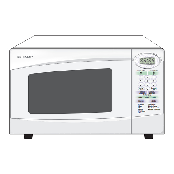
Page 9: Touch Control Panel
R-231NW 2. TOUCH CONTROL PANEL Palomitas de Maiz Descongelacion Nivel de Cronometro Potencia Reloj Detencion Comienzo Cancelacion Minuto Extra Function Rapida Derretir Suavizar Calentar RECALENTAR COCCION 1 Caserola 1 Papa Asada 2 Sopa 2 Verdura Fresca 3 Pizza 3 Verdura Congelada... -
Page 10: Chapter 6. Operation
R-231NW CHAPTER 6. OPERATION [1] DESCRIPTION OF OPERATING SEQUENCE The following is a description of component functions during oven operation. 3. POWER LEVEL COOKING 1. OFF CONDITION When Variable Cooking Power is programmed, the 120 volts Closing the door activates door sensing switch and secondary A.C. -
Page 11: Oven Schenatic
R-231NW [2] OVEN SCHENATIC 1. Off Condition SCHEMATIC NOTE: CONDITION OF OVEN 1. DOOR CLOSED 2. CLOCK APPEARS ON DISPLAY THERMAL CUT-OUT (OVEN) NOTE: " " indicates components with potentials above 250V TEMPERATURE FUSE (OVEN) FUSE N.O. POWER TRANSFORMER COM. -
Page 12: Description And Function Of Components
R-231NW [3] DESCRIPTION AND FUNCTION OF COMPONENTS 1. DOOR OPEN MECHANISM 4. TURNTABLE MOTOR The door is opened by pushing the open button on the control The turntable motor rotates the turntable located on the bottom panel, refer to the Figure D-1. -
Page 13: Chapter 7. Troubleshooting Guide
R-231NW CHAPTER 7. TROUBLESHOOTING GUIDE Never touch any part in the circuit with your hand or an uninsulated tool while the power supply is connected. When troubleshooting the microwave oven, it is helpful to follow the Sequence of Operation in performing the checks. Many of the possible causes of trouble will require that a specifi... -
Page 14: Chapter 8. Test Procedures
R-231NW CHAPTER 8. TEST PROCEDURES [1] Procedure A : MAGNETRON ASSEMBLY TEST 1. Disconnect the power supply cord, and then remove outer case. 2. Open the door and block it open. 3. Discharge high voltage capacitor. 4. To test for an open fi lament, isolate the magnetron from the high voltage circuit. A continuity check across the magnetron fi lament leads should indicate less than 1 ohm. -
Page 15: D: High Voltage Capacitor Test
R-231NW [4] Procedure D : HIGH VOLTAGE CAPACITOR TEST 1. Disconnect the power supply cord, and then remove outer case. 2. Open the door and block it open. 3. Discharge high voltage capacitor. 4. If the capacitor is open, no high voltage will be available to the magnetron. Disconnect input leads and check for short or open be- tween the terminals using an ohmmeter. -
Page 16: F: Primary Interlock System Test
R-231NW [8] Procedure F : PRIMARY INTERLOCK SYSTEM TEST 1. Disconnect the power supply cord, and then remove outer case. 2. Open the door and block it open. 3. Discharge high voltage capacitor. 4. Isolate the switch and connect the ohmmeter to the common (COM.) and normally open (NO) terminal of the switch. The meter should indicate an open circuit with the door open and a closed circuit with the door closed. -
Page 17: H: Blown Minitor Fuse Test
R-231NW [10] Procedure H : BLOWN MINITOR FUSE TEST 1. Disconnect the power supply cord, and then remove outer case. 2. Open the door and block it open. 3. Discharge high voltage capacitor. 4. If the monitor fuse is blown when the door is opened, check the primary interlock relay, secondary interlock switch and monitor switch according to the “TEST PROCEDURE”... -
Page 18: K: Key Unit Test
R-231NW If the key unit is defective. 1) Disconnect the power supply cord and then remove outer case. 2) Open the door and block it open. 3) Discharge high voltage capacitor. 4) Replace the key unit. 5) Reconnect all leads removed from components during testing. -
Page 19: L: Relay Test
R-231NW [14] Procedure L : RELAY TEST 1. Disconnect the power supply cord, and then remove outer case. 2. Open the door and block it open. 3. Discharge high voltage capacitor. 4. Disconnect the leads to the primary of the power transformer. - Page 20 R-231NW 5) Make a visual inspection of the varistor. Check for burned damage and examine the transformer with a tester for the presence of layer short-circuit (check the primary coil resistance which is approximately 915Ω±10%). If any abnormal condition is detected, replace the control unit.
- Page 21 R-231NW CHAPTER 9. TOUCH CONTROL PANEL ASSEMBLY [1] OUTLINE OF TOUCH CONTROL PANEL The touch control section consists of the following units as 3) Power Source Circuit shown in the touch control panel circuit. This circuit generates voltage necessary in the control unit from the AC line voltage.
-
Page 22: Servicing For Touch Control Panel
R-231NW [3] SERVICING FOR TOUCH CONTROL PANEL 1. Precautions for Handling Electronic Components On some models, the power supply cord between the touch control panel and the oven itself is so short that This unit uses CMOS LSI in the integral part of the circuits. -
Page 23: Chapter 10. Precautions For Using Lead- Free Solder
R-231NW CHAPTER 10. PRECAUTIONS FOR USING LEAD-FREE SOLDER [1] Employing lead-free solder The “Main PWB” of this model employs lead-free solder. This is indicated by the “LF” symbol printed on the PWB and in the service manual. The suffi x letter indicates the alloy type of the solder. -
Page 24: Chapter 11. Component Replacement And Adjustment Procedure Warning
R-231NW CHAPTER 11. COMPONENT REPLACEMENT AND ADJUSTMENT PROCEDURE [1] WARNING WARNING AGAINST HIGH VOLTAGE: Microwave ovens contain circuitry capable of producing very high voltage and current, contact with following parts may result in severe, possibly fatal, electric shock. (Example) High Voltage Capacitor, Power Transformer, Magnetron, High Voltage Rectifi er Assembly, High Voltage Harness etc.. -
Page 25: Outer Case Removal
R-231NW [2] OUTER CASE REMOVAL To remove the outer case, procedure as follows. 1. Disconnect the power supply cord. 2. Open the oven door and block it open. 3. Remove the two (2) screws from the lower portion of the rear cabinet using a T20H Torx type or GTXH20-100 screw driver. -
Page 26: Positive Lock Connector (No-Case Type) Removal
R-231NW [6] POSITIVE LOCK CONNECTOR (NO-CASE TYPE) REMOVAL Terminal 1. Disconnect the power supply cord, and remove outer case. ® 2. Open the door and block it open. Positive lock connector 3. Discharge high voltage capacitor. 4. Push the lever of positive lock connector. -
Page 27: Power Supply Cord Replacement
4. Where the corners have been snipped off bend corner areas 4. Insert the tab of the turntable motor cover into the hole of flat. No sharp edges must be evident after removal of the the bottom plate. turntable motor cover. -
Page 28: Door Sensing Switch/Secondary Interlock Switch And Monitor Switch Removal
R-231NW 2. INSTALLATION 1. Install the fan blade to the fan motor shaft according to the CAUTION: DO NOT HIT THE FAN BLADE STRONGLY WHEN following procedure. INSTALLED BECAUSE THE BRACKET MAY BE TRANSFORMED. 2. Hold the center of the bracket which supports the shaft of MAKE SURE THAT THE FAN BLADE ROTATES the fan motor on the fl... -
Page 29: Door Replacement
R-231NW 2. After adjustment, check the following. 1. In and out play of door remains less than 0.5mm when in the latched position. First check upper position of Latch Hook Door latch hook, pushing and pulling upper portion of door toward the oven face. - Page 30 R-231NW 4. SEALER FILM 1. Put the adhesive tape on the backing fi lm of the sealer fi lm as shown in Fig. C-8 Upper Oven Upper 2. Tear the backing fi lm by pulling the adhesive tape. Hinge Oven Hinge 3.
-
Page 31: Chapter 12. Circuit Diagrams
R-231NW CHAPTER 12. CIRCUIT DIAGRAMS [1] Pictorial Diagram (Figure S-1) (RED) Figure S-1 Pictorial Diagram 12 - 1... -
Page 32: Control Panel Circuit (Figure S-2)
R-231NW [2] Control Panel Circuit (Figure S-2) Figure S-2 Control Panel Circuit 12 - 2... -
Page 33: Printed Wiring Board (Figure S-3)
R-231NW [3] Printed Wiring Board (Figure S-3) Figure S-3. Printed Wiring Board 12 - 3... -
Page 34: Parts List
[1] OVEN PARTS ■ INDEX [2] DOOR AND CONTROL PANEL PARTS TOP PAD ASSEMBLY FPADBA585WRKZ POLYETHYLENE BAG SSAKHA014WRE0 DOOR PROTECTION SHEET SPADPA580WRE0 PLASTICSHEET for R-231NW 6-5 INSTRUCTION BOOK SPADPA615WREZ MICROWAVE OVEN 6-1 TURNTABLE TRAY BOTTOM PAD ASSEMBLY FPADBA586WRKZ FOAMSHEET for R-231NW SPAKHA014WREZ... - Page 35 R-231NW [1] OVEN PARTS 7-11 7-11 1-10 4-11 1-13 1-12 4-14 7-10 4-12 4-17 4-10 4-15 4-13 1-11 4-16...
- Page 36 R-231NW PARTS LIST T ’ [1] OVEN PARTS ELECTRONIC PARTS c t i c t i QSW-MA137WRE0 Secondary interlock switch/ Door sensing switch (Interchangeable) QSW-MA147WRE0 Secondary interlock switch/ Door sensing switch (Interchangeable) c t i c t i c t i...
- Page 37 R-231NW [2] DOOR AND CONTROL PANEL PARTS 3-1-2 3-1-1...
- Page 38 R-231NW PARTS CODE DESCRIPTION Q’TY PRICE RANK [2] DOOR AND CONTROL PANEL PARTS CONTROL PANEL PARTS FPNLCC029WRKZ Control panel frame with key unit 3-1-1 PSHEPB414WREZ Graphic sheet 3-1-2 QSW-KA053DRZZ Membrane switch JBTN-B308WRFZ Open button MSPRCA050WRE0 Open button spring DPWB-A482DRKZ Control unit...
- Page 39 R-231NW T ’ [2] DOOR AND CONTROL PANEL PARTS CONTROL PANEL PARTS c t i DOOR PARTS PSHEPA782WREZ Sealer ? MISCELLANEOUS...
- Page 40 R-231NW T ’ [2] DOOR AND CONTROL PANEL PARTS CONTROL PANEL PARTS c t i DOOR PARTS PSHEPA782WREZ Sealer ? MISCELLANEOUS...
- Page 41 [ N ] XOTSF40P08000 1-7-9 NFANJA053WRFZ 1-4-3 NTNT-A034WRF0 1-6-1 [ P ] PCOVPA419WREZ 1-4-8 PCUSGA615WREZ 1-4-14 PCUSGA661WREZ 1-4-13 PCUSGA662WREZ 1-4-12 COPYRIGHT© 2009 BY SHARP CORPORATION PCUSUA501WRP0 1-4-11 PCUSUA633WREZ 2-3-8 PDUC-A908WRWZ 1-4-4 PDUC-A909WRPZ 1-4-9 ALL RIGHTS RESERVED. PHOK-A144WRFZ 1-4-1 PPACGA176WREZ 1-4-10 PSHEPA782WREZ 2-5-6...
Need help?
Do you have a question about the R-231NW and is the answer not in the manual?
Questions and answers