Table of Contents
Advertisement
CAUTION, MICROWAVE RADIATION ............................................................................................................. 1
WARNING .......................................................................................................................................................... 1
PRODUCT SPECIFICATIONS ......................................................................................................................... 2
GENERAL INFORMATION ................................................................................................................................ 2
APPEARANCE VIEW ....................................................................................................................................... 3
OPERATION SEQUENCE ................................................................................................................................ 4
FUNCTION OF IMPORTANT COMPONENTS ................................................................................................ 5
SERVICING ....................................................................................................................................................... 6
TEST PROCEDURE ......................................................................................................................................... 8
TOUCH CONTROL PANEL ............................................................................................................................. 14
COMPONENT REPLACEMENT AND ADJUSTMENT PROCEDURE ........................................................... 18
MICROWAVE MEASUREMENT .................................................................................................................... 23
WIRING DIAGRAM ......................................................................................................................................... 24
PICTORIAL DIAGRAM ................................................................................................................................... 25
CONTROL PANEL CIRCUIT ........................................................................................................................... 26
PARTS LIST ................................................................................................................................................... 27
SERVICE MANUAL
COOK
DEF
KG
QTY
CHECK
MODEL
In interests of user-safety the oven should be restored to its original
condition and only parts identical to those specified should be used.
TABLE OF CONTENTS
SHARP CORPORATION
MICROWAVE OVEN
R-231F
31
R-231F
S1201R231FPJ/
Page
Advertisement
Table of Contents

Subscribe to Our Youtube Channel
Related Manuals for Sharp R-231F


Summary of Contents for Sharp R-231F
-
Page 1: Table Of Contents
R-231F SERVICE MANUAL S1201R231FPJ/ MICROWAVE OVEN COOK CHECK R-231F MODEL In interests of user-safety the oven should be restored to its original condition and only parts identical to those specified should be used. TABLE OF CONTENTS Page CAUTION, MICROWAVE RADIATION ......................1 WARNING ................................ - Page 2 R-231F...
-
Page 3: Caution Microwave Radiation
PRODUCT SPECIFICATIONS R-231F GENERAL IMPORTANT INFORMATION APPEARANCE VIEW This Manual has been prepared to provide Sharp Corp. Service engineers with Operation and Service Information. It is recommended that service engineers carefully study the OPERATING SEQUENCE entire text of this manual, so they will be qualified to render satisfactory customer service. -
Page 4: Product Specifications
R-231F PRODUCT SPECIFICATIONS ITEM DESCRIPTION Power Requirements 230 - 240 Volts 50 Hertz Single phase, 3 wire earthed Power Consumption 1.21 kW Power Output 800 watts nominal of RF microwave energy (IEC Test Procedure) Operating frequency 2450 MHz Case Dimensions... -
Page 5: Appearance View
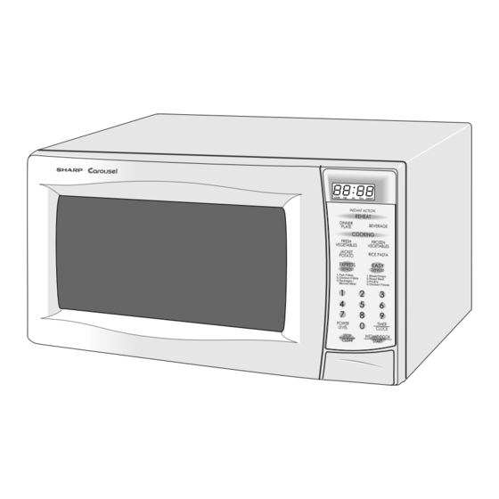
R-231F APPEARANCE VIEW OVEN 10 4 1. Door open button 6. Door seals sealing surfaces 11. Power supply cord 2. Oven lamp 7. Coupling 12. Ventilation openings 3. Door hinges 8. Control panel 13. Turntable 4. Door safety latches 9. Liquid crystal display 14. -
Page 6: Operation Sequence
R-231F OPERATION SEQUENCE OFF CONDITION The oven lamp remains on even if the oven door is Closing the door activates all door interlock switches opened after the cooking cycle has been interrupted, (1st. latch switch, 2nd. interlock relay control switch). -
Page 7: Function Of Important Components
R-231F FUNCTION OF IMPORTANT COMPONENTS TEMPERATURE FUSE DOOR OPEN MECHANISM The temperature fuse, located on the top of the oven The door is opened by pushing the open button on the cavity, is designed to prevent damage to the oven by fire. -
Page 8: Servicing
3D checks and re-examine the connections to screwdriver. the component being tested. Sharp recommend that wherever possible fault-finding is carried out with the supply disconnected. It may, in some cases, be necessary to connect the supply after the outer case has been removed, in this event carry out 3D checks and then disconnect the leads to the primary of the power transformer. - Page 9 R-231F CK = Check / RE = Replace TEST PROCEDURE A B C D E E E F G G H K M N I L J RECKCKRE CKCKCKCKCK POSSIBLE CAUSE DEFECTIVE PARTS PROBLEM CONDITION Home fuse blows when power supply cord is plugged into wall outlet.
-
Page 10: Test Procedure
R-231F TEST PROCEDURES PROCEDURE COMPONENT TEST LETTER MAGNETRON TEST NEVER TOUCH ANY PART IN THE CIRCUIT WITH YOUR HAND OR AN INSULATED TOOL WHILE THE OVEN IS IN OPERATION. CARRY OUT 3D CHECKS. Isolate the magnetron from the high voltage circuit by removing all leads connected to the filament terminal. - Page 11 R-231F TEST PROCEDURES PROCEDURE COMPONENT TEST LETTER Room temperature ....... To = 21˚C Initial temperature ....T1 = 11 C Temperature after (52 + 3) = 55 sec..............T2 = 21 C Temperature difference Cold-Warm ..............T1 = 10 C Measured output power The equation is “P = 80 x T”...
- Page 12 R-231F TEST PROCEDURES PROCEDURE COMPONENT TEST LETTER HIGH VOLTAGE CAPACITOR TEST CARRY OUT 3D CHECKS. A. Isolate the high voltage capacitor from the circuit. B. Continuity check must be carried out with measuring instrument which is set to the highest resistance range.
- Page 13 R-231F TEST PROCEDURES PROCEDURE COMPONENT TEST LETTER If incorrect readings are obtained, replace the motor. CARRY OUT 4R CHECKS. FUSE T6.3A CARRY OUT 3D CHECKS. If the fuse T6.3A is blown when the door is opened, check the 1st latch switch, 2nd. interlock relay control switch, monitor switch and 2nd.
- Page 14 R-231F TEST PROCEDURES PROCEDURE COMPONENT TEST LETTER 2-1 Programming problems. a) When touching the pads, a certain group of pads do not produce a signal. b) When touching the pads, no pads produce a signal. 2-2 Display problems. a) For a certain digit, all or some segments do not light up.
- Page 15 R-231F TEST PROCEDURES PROCEDURE COMPONENT TEST LETTER PROCEDURES TO BE TAKEN WHEN THE FOIL PATTERN ON THE PRINTED WIRING BOARD (PWB) IS OPEN To protect the electronic circuits, this model is provided with a fine foil pattern added to the primary on the PWB, this foil pattern acts as a fuse.
-
Page 16: Touch Control Panel
R-231F TOUCH CONTROL PANEL ASSEMBLY OUTLINE OF TOUCH CONTROL PANEL The touch control section consists of the following units as 3) Power Source Circuit shown in the touch control panel circuit. This circuit generates voltage necessary in the control unit from the AC line voltage. In addition, the synchro-... - Page 17 R-231F DESCRIPTION OF LSI The I/O signal of the LSI are detailed in the following table. Pin No. Signal Description RESET Auto clear terminal. Signal is input to reset the LSI to the initial state when power is supplied. Temporarily set to “L” level the moment power is supplied, at this time the LSI is reset.
- Page 18 R-231F Pin No. Signal Description Signal similar to K02. When either G8 line on key matrix is touched, a corresponding signal will be input into K00. Signal similar to K02. When either G9 line on key matrix is touched, a corresponding signal will be input into K01.
- Page 19 R-231F SERVICING 1. Precautions for Handling Electronic Components door being closed. As for the sensor-related This unit uses CMOS LSI in the integral part of the controls of the touch control panel, checking circuits. When handling these parts, the following pre- them is possible if the dummy resistor(s) with cautions should be strictly followed.
-
Page 20: Component Replacement And Adjustment Procedure
WARNING FOR WIRING To prevent an electric shock, take the following and Oven cavity. manners. 3) Sharp edge: 1. Before wiring, Oven cavity, Waveguide flange, other metallic 1) Disconnect the power supply. plate. 2) Open the door and wedge the door open. - Page 21 R-231F 3. Remove the three (3) screws holding the magnetron to CAUTION: WHEN REPLACING THE MAGNETRON, the waveguide. BE SURE THE R.F. GASKET IS IN PLACE 4. Remove the magnetron from waveguide. AND THE MAGNETRON MOUNTING 5. Now, the magnetron is free.
- Page 22 R-231F motor to the oven cavity. 5. Re-install the turntable motor cover to the bottom plate 8. Remove the turntable motor from the oven cavity. with one (1) screw. 9. Remove the TTM packing from the turntable motor. TTM packing 10.Now, the turntable motor is free.
- Page 23 R-231F Re-install 2. Install the earth wire lead of power supply cord and the earth angle to the oven cavity with one (1) screw and 1. Insert the moulding cord stopper of power supply cord tight the screw. into the square hole of the rear cabinet, referring to the 3.
- Page 24 R-231F DOOR REPLACEMENT REMOVAL wave radiation emission limitation standards. 1. Disconnect the oven from the power supply. After any service, make sure of the following : 2. Open the door slightly. 1. Door latch heads smoothly catch latch hook through 3.
-
Page 25: Microwave Measurement
R-231F MICROWAVE MEASUREMENT Recommended instruments are: After adjustment of door latch switches, monitor switch and door are completed individually or collectively, the NARDA 8100 following leakage test must be performed with a survey NARDA 8200 instrument and it must be confirmed that the result meets... -
Page 26: Wiring Diagram
R-231F SCHEMATIC NOTE: CONDITION OF OVEN 1. DOOR CLOSED. 2. CLOCK APPEARS ON DISPLAY. NOTE: " " indicates components with potential above 250V. NOISE FILTER COM. N.O. RY-2 2ND. RY-1 INTERLOCK RELAY CONTROL UNIT 2ND. INTERLOCK RELAY CONTROL SWITCH 1ST. LATCH... -
Page 27: Pictorial Diagram
R-231F... -
Page 28: Control Panel Circuit
R-231F COM1 COM2 COM3 SEG1 SEG2 SEG3 SEG4 SEG5 SEG6 SEG7 SEG8 SEG9 SEG10 SEG11 SEG12 SEG13 COM1 SEG14 COM0 SEG15 SEG16 SEG17 SEG18 SEG19 /25v 0.01 /25v 0.01 /25v 0.01 20kF /25v /25v 0.01 4.7k /25v 3.3k HZ4B3 /10v... -
Page 29: Parts List
R-231F PARTS LIST Note: The parts marked " " may cause undue microwave exposure. The parts marked "*" are used in voltage more than 250V. REF. NO. PART NO. DESCRIPTION Q'TY CODE ELECTRIC PARTS 1- 1 QACCAA048WRZZ Power supply cord... - Page 30 R-231F Note: The parts marked " " may cause undue microwave exposure. The parts marked "*" are used in voltage more than 250V. REF. NO. PART NO. DESCRIPTION Q'TY CODE 7- 4 LX-CZ0052WRE0 Special screw 7- 5 LX-EZA042WRE0 Special screw...
- Page 31 R-231F OVEN AND CABINET PARTS 4-13 1-13 4-11 1-12 4-12 1-10 4-10 1-11 1-14 1-10...
- Page 32 Not replaceable items. SPAKCD668WREZ TRAY PAD ASSY (CPADBA287WRKZ) COPYRIGHT © 2002 BY SHARP CORPORATION ALL RIGHTS RESERVED. No part of this publication may be reproduced, stored in retrieval systems, or transmitted in any form or by any means, electronic, mechanical, photocopying, recording, or otherwise, without prior written permission of the publisher.
Need help?
Do you have a question about the R-231F and is the answer not in the manual?
Questions and answers
Tuch penal not working
If the touch panel on the Sharp R-231F is not working, follow these steps to diagnose the issue:
1. Press the STOP/CLEAR pad. If the display does not clear, check the flat ribbon cable connection.
2. Verify that the 2nd interlock relay control switch is working correctly (contacts should be closed when the door is closed and open when the door is open).
3. If the interlock relay control switch is good, disconnect the flat ribbon cable connecting the key unit to the control unit.
4. Ensure the 2nd interlock relay control switch is closed.
5. Use the Key unit matrix from the control panel schematic and place a jumper wire between the corresponding pins for the STOP/CLEAR pad.
6. If the control unit responds with a beep and clears, the key unit is faulty and must be replaced.
7. If the control unit does not respond, it is faulty and must be replaced.
These steps will help determine if the touch panel (key unit) or the control unit is defective.
This answer is automatically generated