Table of Contents
Advertisement
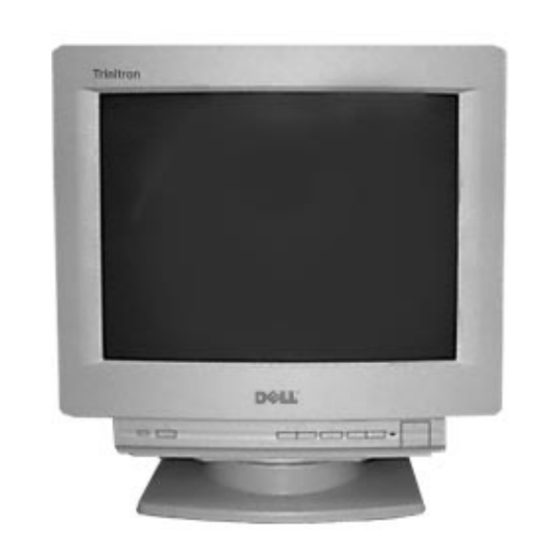
SERVICE MANUAL
Picture tube
0.25 mm aperture grill pitch
17 inches measured diagonally
90-degree deflection
Video image area
(16" maximum viewing image)
Approx. 329.5 x 243 mm (w/h)
(13 x 9
Logical resolution
Horizontal: Max. 1280 dots
Vertical: Max. 1024 lines
Physical resolution
Horizontal: Max. 1024 dots
Vertical: Max. 768 lines
Standard image area
Approx. 312 x 234 mm (w/h)
(12
3/8
x 9
Input signal
Video
Analog RGB (75 ohms typical)
0.7 Vp-p, Positive
Sync
External HD/VD, Composite
Polarity Free TTL
Video Composite (Sync on Green)
0.3 Vp-p, Negative
SPECIFICATIONS
5/8
inches)
1/4
inches)
— 1 —
Canadian Model
S. Hemisphere Model
D-1H
Power Consumption
Maximum
Nominal
Deflection frequency
AC input voltage / current
Dimensions
Mass
Design and specifications are subject to change without notice.
COLOR MONITOR
D1025TM
D1025TM
D1025TM
US Model
Japan Model
Chassis No. SCC-L07D-A
CHASSIS
120W
100W, 341 BTU/h
Horizontal: 30 to 85 KHz
Vertical: 50 to120 Hz
100 to 120 V, 50/60 Hz, 1.8 A
220 to 240V, 50/60Hz, 1A
406 x 432 x 420 (w/h/d)
(16 x 17
1/8
x 16
5/8
inches)
Approx. 18.0 kg (39 lb 11 oz)
R
Advertisement
Table of Contents

Related Manuals for Dell D1025TM - UltraScan 1000HS - 17" CRT Display


Summary of Contents for Dell D1025TM - UltraScan 1000HS - 17" CRT Display
-
Page 1: Service Manual
D1025TM D1025TM SERVICE MANUAL D1025TM US Model Canadian Model Japan Model S. Hemisphere Model Chassis No. SCC-L07D-A D-1H CHASSIS SPECIFICATIONS Power Consumption Picture tube 0.25 mm aperture grill pitch Maximum 17 inches measured diagonally 120W Nominal 90-degree deflection 100W, 341 BTU/h Deflection frequency Video image area (16"... - Page 2 D1025TM POWER SAVING FUNCTION NOTE: If no video signal is input to the monitor, the This monitor has three Power Saving modes. "NO INPUT SIGNAL" message appears. After By sensing the absence of a video signal from the about 30 seconds, the Power Saving function computer, it reduces power consumption as follows: automatically puts the monitor into active-off mode and the indicator lights up orange.
- Page 3 D1025TM SAFETY CHECK-OUT (US Model only) After correcting the original service problem, perform LEAKAGE TEST the following safety checks before releasing the set to the The AC leakage from any exposed metal part to earth ground customer: and from all exposed metal parts to any exposed metal part having a return to chassis, must not exceed 0.5 mA (500 microampere).
-
Page 4: Table Of Contents
D1025TM TABLE OF CONTENTS Section Title Page 1. GENERAL ................... 5 2. DISASSEMBLY 2-1. Cabinet Removal ............10 2-2. Service Position .............. 10 2-3. D and A Board Removal..........10 2-4. Picture Tube Removal ........... 11 3. SAFETY RELATED ADJUSTMENT ......... 12 4. -
Page 5: General
Warning Messages ..............12 Parts and Controls ..............5 Troubleshooting ..............12 The OSD (On-screen Display) System ......... 6 Dell Computer Corporation’s Environmental Program . 14 Resetting the Adjustments ............. 9 Appendix ................109 Precautions 6 u (POWER) switch and indicator (page 11) - Page 6 Customizing Your Monitor Getting Started Customizing Your Monitor 3 Using the SCREEN OSD Adjusting the Picture Brightness and Contrast Adjusting the Settings You can adjust the convergence of the picture and cancel the 1 Using the COLOR OSD picture’s moire using the SCREEN OSD. Convergence is the alignment of the Red, Green and Blue Press the ¨...
- Page 7 Getting Started Customizing Your Monitor Customizing Your Monitor 8 Using the GEOMETRY OSD Resetting the Adjustments 4 Using the ZOOM OSD 6 Using the SIZE OSD You can adjust the picture’s geometry using the GEOMETRY You can enlarge or reduce the picture size using the ZOOM You can adjust the picture size using the SIZE OSD.
- Page 8 Additional Information Customizing Your Monitor Warning Messages Graphic Enhancement Mode (GEM) If there is something wrong with the input signal, one of the following messages appears. The input signal condition You can automatically change the characteristics of the picture INFORMATION to match the way you use your monitor with the Graphic “OUT OF SCAN RANGE”...
- Page 9 Getting Started Additional Information Symptom Check these items You cannot adjust the monitor • If the Control Lock function is set to “ON,” set it to “OFF” using the OPTION OSD (page 8). with the buttons on the front panel Screen image is not centered or •...
-
Page 10: Disassembly
D1025TM SECTION 2 DISASSEMBLY 2-1. CABINET REMOVAL 2-2. SERVICE POSITION Two claws PUSH Cabinet PUSH A board D board Two screws (BVTP 4 x 16) 2-3. D and A BOARD REMOVAL A board Five screws (BVTP 3 x 12) One screw (BVTT 4 x 8) Cable stopper Two screws... -
Page 11: Picture Tube Removal
D1025TM 2-4. PICTURE TUBE REMOVAL Demagnetization coil Two screws (BVTP 4 x 16) Tension spring A board Neck assy Deflection yoke Four screws (Tapping screw 5) Stand assy (D board) Picture tube shield Anode cap Cushion REMOVAL OF THE ANODE-CAP NOTE: Short circuit the anode of the picture tube and the anode cap to the metal chassis, CRT shield or carbon painted on the CRT, after removing the anode. -
Page 12: Safety Related Adjustment
D1025TM SECTION 3 SAFETY RELATED ADJUSTMENT When replacing parts shown in the table below, the b) HV Hold-Down Check following operational checks must be performed as a 1) Using an external DC Power supply, apply the safety precaution against X-ray emissions from the unit. voltage shown below between cathode of D517 "... -
Page 13: Adjustments
D1025TM SECTION 4 ADJUSTMENTS Connect the communication cable of the connector located on the D board on the monitor. Run the service software and then follow the instructions. 1-690-391-21 A-1500-819-A 3-702-691-01 Interface Unit Connector Attachment IBM AT Computer To BUS CONNECTOR as a Jig D-sub mini Din... - Page 14 D1025TM Receive White cross-hatch. Convergence Specification Adjust HMC and VMC at six-pole magnet. < 6 Pole Magnet> Horizontal and Vertical 0.30mm 0.24mm 0.30mm 0.30mm Focus adjustment Receive R.B. cross-hatch. Adjust focus (V) and focus (H) for optimum focus. Adjust H.TILT by swinging the DY neck right and left. Adjust XCV with XCV core.
-
Page 15: Circuit Boards Location
D1025TM 5-2. CIRCUIT BOARDS LOCATION 5-3. SCHEMATIC DIAGRAMS AND PRINTED WIRING BOARDS Note: • All capacitors are in F unless otherwise noted. pF: • When replacing parts shown in the table below, 50 WV or less are not indicated except for electrolytic. be sure to perform the safety related adjustment. -
Page 18: Exploded Views
D1025TM SECTION 6 EXPLODED VIEWS Note: • • Items with no part number and no descrip- Items marked " " are not stocked tion are not stocked because they are sel- since they are seldom required for routine The components identified by shading dom required for routine service. -
Page 19: Chassis (Japan, S. Hemisphere)
D1025TM Note: • • Items with no part number and no descrip- Items marked " " are not stocked tion are not stocked because they are sel- since they are seldom required for routine The components identified by shading dom required for routine service. service. -
Page 20: Packing Materials
D1025TM 6-3. PACKING MATERIALS (FOR ALL MODELS) REF.NO. PART NO. DESCRIPTION REMARK REF.NO. PART NO. DESCRIPTION REMARK REF.NO. PART NO. DESCRIPTION REMARK 3-861-661-11 MANUAL, INSTRUCTION (US,CND,J) 3-861-661-21 MANUAL, INSTRUCTION (SH) 52 * 4-062-365-01 CUSHION (UPPER) (US, CND,J) 52 * 4-063-118-01 CUSHION (UPPER) (SH) 53 ¡... -
Page 21: Electrical Parts List
D1025TM SECTION 7 ELECTRICAL PARTS LIST The components identified by [ in this manual RESISTORS Note: have been carefully factory-selected for each • All resistors are in ohms set in order to satisfy regulations regarding X- REF.NO. PART NO. The components identified by shading DESCRIPTION REMARK REF.NO. - Page 22 D1025TM Note: Note: The components identified by shading Les composants identifies per un trame et une marque and mark ¡ ¡ ¡ ¡ ¡ ¡ ¡ ¡ ¡ ¡ sont critiques pour la securite. Ne les remplacer are critical for safety. Replace only with part number specified.
- Page 23 D1025TM Note: Note: The components identified by shading Les composants identifies per un trame and mark ¡ ¡ ¡ ¡ ¡ et une marque ¡ ¡ ¡ ¡ ¡ sont critiques pour la are critical for safety. Replace only with part number specified. securite.
- Page 24 D1025TM Note: Note: The components identified by shading Les composants identifies per un trame et une marque and mark ¡ ¡ ¡ ¡ ¡ ¡ ¡ ¡ ¡ ¡ sont critiques pour la securite. Ne les remplacer are critical for safety. Replace only with part number specified.
- Page 25 D1025TM Note: Note: The components identified by shading Les composants identifies per un trame et une marque and mark ¡ ¡ ¡ ¡ ¡ ¡ ¡ ¡ ¡ ¡ sont critiques pour la securite. Ne les remplacer are critical for safety. Replace only with part number specified.
- Page 26 D1025TM Note: Note: The components identified by shading Les composants identifies per un trame et une marque and mark ¡ ¡ ¡ ¡ ¡ ¡ ¡ ¡ ¡ ¡ sont critiques pour la securite. Ne les remplacer are critical for safety. Replace only with part number specified.
- Page 27 D1025TM Note: Note: The components identified by shading Les composants identifies per un trame et une marque and mark ¡ ¡ ¡ ¡ ¡ ¡ ¡ ¡ ¡ ¡ sont critiques pour la securite. Ne les remplacer are critical for safety. Replace only with part number specified.
- Page 28 D1025TM Note: Note: The components identified by shading Les composants identifies per un trame et une marque and mark ¡ ¡ ¡ ¡ ¡ ¡ ¡ ¡ ¡ ¡ sont critiques pour la securite. Ne les remplacer are critical for safety. Replace only with part number specified.
- Page 29 D1025TM Note: Note: The components identified by shading Les composants identifies per un trame et une marque and mark ¡ ¡ ¡ ¡ ¡ ¡ ¡ ¡ ¡ ¡ sont critiques pour la securite. Ne les remplacer are critical for safety. Replace only with part number specified.
- Page 30 D1025TM The components identified by [ [ [ [ [ in this manual have been Note: The components identified by shading carefully factory-selected for each set in order to satisfy and mark ¡ ¡ ¡ ¡ ¡ are critical for safety. regulations regarding X-ray radiation.
- Page 31 D1025TM NOTES: REF.NO. PART NO. DESCRIPTION REMARK REF.NO. PART NO. DESCRIPTION REMARK — 42 —...
- Page 32 D1025TM NOTES: REF.NO. PART NO. DESCRIPTION REMARK REF.NO. PART NO. DESCRIPTION REMARK — 43 —...
- Page 33 D1025TM REF.NO. PART NO. DESCRIPTION REMARK REF.NO. PART NO. DESCRIPTION REMARK English 97KJ74020-1 Printed in U.S.A. 9-978-830-01 © 1997.11 — 44 —...
Need help?
Do you have a question about the D1025TM - UltraScan 1000HS - 17" CRT Display and is the answer not in the manual?
Questions and answers