Advertisement
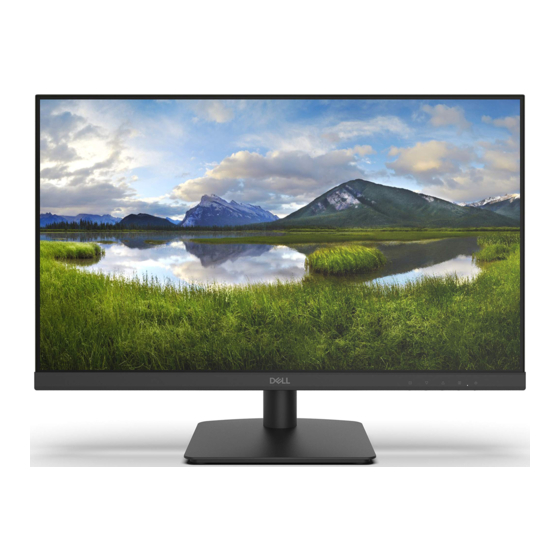
24"LCDColorMonitor
Service
Service
Service
ANYPERSONATTEMPTINGTOSERVICETHISCHASSISMUSTFAMILIARIZEHIMSELFWITHTHECHASSISAND
BEAWAREOFTHENECESSARYSAFETYPRECAUTIONSTOBEUSEDWHENSERVICINGELECTRONICEQUIPME
NTCONTAINING HIGH VOLTAGES.
CAUTION: USEASEPARATEISOLATIONTRANSFOMERFORTHIS UNITWHENSERVICING
SAFETYNOTICE
1
Dell D2421H
Advertisement
Table of Contents

Summary of Contents for Dell D2421H
- Page 1 Dell D2421H 24"LCDColorMonitor Service Service Service SAFETYNOTICE ANYPERSONATTEMPTINGTOSERVICETHISCHASSISMUSTFAMILIARIZEHIMSELFWITHTHECHASSISAND BEAWAREOFTHENECESSARYSAFETYPRECAUTIONSTOBEUSEDWHENSERVICINGELECTRONICEQUIPME NTCONTAINING HIGH VOLTAGES. CAUTION: USEASEPARATEISOLATIONTRANSFOMERFORTHIS UNITWHENSERVICING...
- Page 2 TABLE OF CONTENTS 1. Important Safety Notice..............................3 2. Exploded 2D Drawing..............................4 3. Wiring connectivity diagram............................5 4. Mechanical Instruction..............................6-10...
-
Page 3: Important Safety Notice
Accordingly, a servicer who uses a service procedure or tool which is not recommended by DELL must first satisfy himself thoroughly that neither his safety nor the safe operation of the equipment will be jeopardized by these rvice method selected. -
Page 4: Exploded 2D Drawing
Exploded 2D Drawing... -
Page 5: Wiring Connectivity Diagram
3. Wiring connectivity diagram... -
Page 6: Mechanical Instruction
4.Mechanical Instruction DELLE2420H 1 Disassembly Procedures: Use plastic picks to wedge from Teardown hole, release rear cover, then pull up Turn off power carefully the rear cover in order of arrow preference for unlocking mechanisms of rear cover. Unplug external cables from product Put it on a protective cushion and remove Remove stand from product: press the the rear cover. - Page 7 DELLE2420H Tear off 2 pieces of aluminum foil (pic.7.1) Lift up the bracket chassis module and put it Teardown the Key board from BEZEL, then on a protector cushion. Please pay attention disconnect the keypad cable from the to ESD protection(wear ESD ring and so on). connectors of the Key board(pic.7.2).
- Page 8 DELLE2420H Remove the Mylar from the hooks of the bracket chassis module. Use a Philips‐head screwdriver to remove 4 screws for unlocking the power board, then remove the board from the hooks of the bracket chassis. (No.1~3 screw size=M3x6, Torque=4.5~6.5kgfxcm No.4 screw size=M4x6, Torque=4.5~6.5kgfxcm) Use a Philips‐head screwdriver to remove 11 screws for unlocking the bezel, then remove bezel...
- Page 9 5. Exploded View...


Need help?
Do you have a question about the D2421H and is the answer not in the manual?
Questions and answers