Intel DP965LT Product Manual
Desktop board
Hide thumbs
Also See for DP965LT:
- Specification (94 pages) ,
- Specification (8 pages) ,
- Product manual (74 pages)
Table of Contents
Advertisement
Advertisement
Table of Contents

Related Manuals for Intel DP965LT


Summary of Contents for Intel DP965LT
- Page 1 Intel® Desktop Board DP965LT Product Guide Order Number: D46810-003...
-
Page 2: Revision History
Intel may make changes to specifications and product descriptions at any time, without notice. Desktop Board DP965LT may contain design defects or errors known as errata which may cause the product to deviate from published specifications. Current characterized errata are available on request. -
Page 3: Intended Audience
The suitability of this product for other PC or embedded non-PC applications or other environments, such as medical, industrial, alarm systems, test equipment, etc. may not be supported without further evaluation by Intel. Document Organization The chapters in this Product Guide are arranged as follows:... -
Page 4: Box Contents
Intel Desktop Board DP965LT Product Guide Terminology The table below gives descriptions of some common terms used in the product guide. Term Description Gigabyte (1,073,741,824 bytes) Gigahertz (one billion hertz) Kilobyte (1024 bytes) Megabyte (1,048,576 bytes) Mbit Megabit (1,048,576 bits) -
Page 5: Table Of Contents
Supported Operating Systems ................10 Desktop Board Components.................. 11 Processor ......................13 Main Memory ...................... 14 ® Intel P965 Express Chipset ................. 15 Onboard Audio Subsystem ................... 15 Input/Output (I/O) Controller ................16 LAN Subsystem....................16 LAN Subsystem Software................16 RJ-45 LAN Connector LEDs ................ - Page 6 Connecting to the HD Audio Link Header ............43 Connecting to the IEEE 1394a Header ............43 ® Installing a Front Panel Audio Solution for Intel High Definition Audio ....43 Connecting to the Serial Port Header.............. 45 Connecting to the Alternate Front Panel Power LED Header....... 45 Connecting to the Front Panel Header ............
- Page 7 2. LAN Connector LEDs ..................16 3. Location of Standby Power Indicator ..............22 4. Installing the I/O Shield ................. 27 5. Desktop Board DP965LT Mounting Screw Hole Locations ........28 6. Lift Socket Lever ................... 29 7. Lift the Load Plate..................29 8.
- Page 8 4. HD Audio Link Header Signal Names ..............43 5. IEEE 1394a Signal Header Names..............43 6. Front Panel Audio Header Signal Names for Intel High Definition Audio....43 7. AC ’97 Audio Header Signal Names ..............44 8. Serial Port Header Signal Names ..............45 9.
-
Page 9: Desktop Board Features
1 Desktop Board Features This chapter briefly describes the main features of Intel Desktop Board DP965LT. ® Table 1 summarizes the major features of the desktop board. Table 1. Feature Summary ATX (320.04 millimeters [11.60 inches] x 243.84 millimeters Form Factor [9.60 inches]) -
Page 10: Supported Operating Systems
LAN Support Intel 82566DC Gigabit (10/100/1000 Mb/s) Ethernet LAN controller Related Links: For more information about Desktop Board DP965LT, including the Technical Product Specification (TPS), BIOS updates, and device drivers, go to: http://support.intel.com/support/motherboards/desktop/ Supported Operating Systems The desktop board supports the following operating systems: •... -
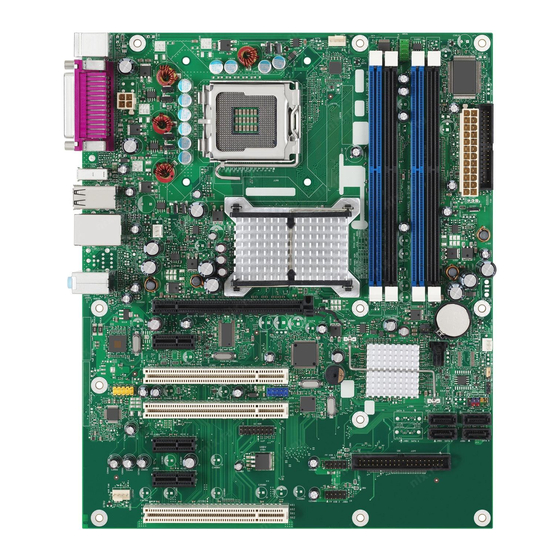
Page 11: Desktop Board Components
Desktop Board Features Desktop Board Components Figure 1 shows the approximate location of the major components on Desktop Board DP965LT. Figure 1. Desktop Board DP965LT Components... -
Page 12: Related Links
Intel Desktop Board DP965LT Product Guide Table 2. Desktop Board DP965LT Components Label Description PCI bus connector 3 Auxiliary chassis fan header (4-pin) PCI Express x 1 connector 3 PCI Express x 1 connector 2 High Definition Audio Link header... -
Page 13: Processor
Processors are not included with the desktop board and must be purchased separately. The processor connects to the desktop board through the LGA775 socket. The supported processors list for Desktop Board DP965LT is located on the web at: http://support.intel.com/support/motherboards/desktop/ Related Links:... -
Page 14: Main Memory
Up to 4.0 GB utilizing 512 Mb or 1 Gb technology • Up to 8.0 GB utilizing 1 Gb technology NOTE 1 Gb memory technology is not supported on DDR2-800 DIMMs. Intel recommends using memory from the tested memory lists, available at: http://www.cmtlabs.com/mbsearch.asp http://www.intel.com/products/motherboard/index.htm?iid=HMPAGE+Header_2_Pro duct_MB Related Links: Go to the following links or pages for more information about: •... -
Page 15: Intel P965 Express Chipset
Intel P965 Express Chipset Memory Controller Hub (MCH) • Intel 82801HB I/O Controller Hub (ICH8) Related Links: Go to the following link for more information about the Intel P965 Express Chipset: http://developer.intel.com/design/nav/pcserver.htm Onboard Audio Subsystem Desktop Board DP965LT has a flexible 6-channel (5.1) onboard audio subsystem that includes a SigmaTel STAC9227 audio codec and an HD Audio Link header. -
Page 16: Input/Output (I/O) Controller
• Configurable EEPROM that contains the MAC address LAN Subsystem Software For LAN software and drivers, refer to the DP965LT link on Intel’s World Wide Web site http://support.intel.com/support/motherboards/desktop RJ-45 LAN Connector LEDs Two LEDs are built into the RJ-45 LAN connector located on the back panel (see Figure 2). -
Page 17: Hi-Speed Usb 2.0 Support
Desktop Board Features Table 3 describes the LED states when the board is powered up and the LAN subsystem is operating. Table 3. LAN Connector LEDs LED Color LED State Indicates Green LAN link is not established LAN link is established Blinking LAN activity is occurring 10 Mb/s data rate... -
Page 18: Serial Ata
Intel Desktop Board DP965LT Product Guide Serial ATA The desktop board supports four Serial ATA channels (3.0 Gb/s) via ICH8, connecting one device per channel. Expandability For system expansion, the desktop board provides the following: • Three PCI Express x1 connectors •... -
Page 19: Security Passwords
For instructions on resetting the password, see Clearing Passwords on page 52. Hardware Management Features The hardware management features of Desktop Board DP965LT enable the board to be compatible with the Wired for Management (WfM) specification. The board has several hardware management features including the following: •... -
Page 20: Chassis Intrusion
Intel Desktop Board DP965LT Product Guide Chassis Intrusion The board supports a chassis security feature that detects if the chassis cover has been removed. The security feature uses a mechanical switch on the chassis that can be connected to the chassis intrusion header on the desktop board. See Figure 26 on page 50 for the location of the chassis intrusion header. -
Page 21: Fan Headers
Desktop Board Features Fan Headers The function/operation of the fans is as follows: • The fans are on when the computer is in the ACPI S0 state. • The fans are off when the computer is in the ACPI S3, S4, or S5 state. •... -
Page 22: +5 V Standby Power Indicator Led
Intel Desktop Board DP965LT Product Guide The desktop board supports the PCI Bus Power Management Interface Specification. Add-in cards that support this specification can participate in power management and can be used to wake the computer. +5 V Standby Power Indicator LED... -
Page 23: Wake From Usb
Desktop Board Features Wake from USB NOTE Wake from USB requires the use of a USB peripheral that supports Wake from USB. USB bus activity wakes the computer from an ACPI S3 state. Wake from PS/2 Keyboard/Mouse PS/2 keyboard/mouse activity wakes the computer from an ACPI S3 state. PME# Signal Wake-up Support When the PME# signal on the PCI bus is asserted, the computer wakes from an ACPI S3, S4, or S5 state. - Page 24 Intel Desktop Board DP965LT Product Guide...
-
Page 25: Installing And Replacing Desktop Board Components
2 Installing and Replacing Desktop Board Components This chapter tells you how to: • Install the I/O shield • Install and remove the desktop board • Install and remove a processor • Install and remove memory • Install and remove a PCI Express x16 card •... -
Page 26: Installation Precautions
Intel Desktop Board DP965LT Product Guide Installation Precautions When you install and test the Intel desktop board, observe all warnings and cautions in the installation instructions. To avoid injury, be careful of: • Sharp pins on connectors • Sharp pins on printed circuit assemblies •... -
Page 27: Installing The I/O Shield
Installing and Replacing Desktop Board Components Installing the I/O Shield The desktop board comes with an I/O shield. When installed in the chassis, the shield blocks radio frequency transmissions, protects internal components from dust and foreign objects, and promotes correct airflow within the chassis. Install the I/O shield before installing the desktop board in the chassis. -
Page 28: Installing And Removing The Desktop Board
Refer to your chassis manual for instructions on installing and removing the desktop board. Figure 5 shows the location of the mounting screw holes for Desktop Board DP965LT. Figure 5. Desktop Board DP965LT Mounting Screw Hole Locations... -
Page 29: Installing And Removing A Processor
Installing and Replacing Desktop Board Components Installing and Removing a Processor Instructions on how to install the processor to the desktop board are given below. Installing a Processor CAUTION Before installing or removing the processor, make sure the AC power has been removed by unplugging the power cord from the computer;... -
Page 30: Remove The Protective Socket Cover
Intel Desktop Board DP965LT Product Guide 4. Remove the plastic protective socket cover from the load plate (Figure 8). Do not discard the protective socket cover. Always replace the socket cover if the processor is removed from the socket. Figure 8. Remove the Protective Socket Cover 5. -
Page 31: Install Processor
Installing and Replacing Desktop Board Components 6. Hold the processor with your thumb and index fingers oriented as shown in Figure 10. Make sure fingers align to the socket cutouts (Figure 10, A). Align notches (Figure 10, B) with the socket (Figure 10, C). Lower the processor straight down without tilting or sliding the processor in the socket. -
Page 32: Installing The Processor Fan Heat Sink
Intel Desktop Board DP965LT Product Guide Installing the Processor Fan Heat Sink Desktop Board DP965LT has an integrated processor fan heat sink retention mechanism (RM). For instructions on how to attach the processor fan heat sink to the integrated processor fan heat sink RM, refer to the boxed processor manual or the... -
Page 33: Removing The Processor
DIMMs that support the Serial Presence Detect (SPD) data structure. You can access the PC Serial Presence Detect Specification at: http://www.intel.com/technology/memory/ddr/specs/dda18c32_64_128x72ag_a.pdf Desktop board DP965LT has four 240-pin DDR2 DIMM sockets arranged as DIMM 0 and DIMM 1 in both Channel A and Channel B. Guidelines for Dual Channel Memory Configuration Before installing DIMMs, read and follow these guidelines for dual channel configuration. -
Page 34: Three Dimms
Intel Desktop Board DP965LT Product Guide If additional memory is to be used, install another matched pair of DIMMs in DIMM 1 (black) in both channels A and B (see Figure 14). Figure 14. Dual Channel Memory Configuration Example 2... -
Page 35: Installing Dimms
Installing and Replacing Desktop Board Components Installing DIMMs To make sure you have the correct DIMM, place it on the illustration of the DDR2 DIMM in Figure 16. All the notches should match with the DDR2 DIMM. Figure 16. Use DDR2 DIMMs... -
Page 36: Installing A Dimm
Intel Desktop Board DP965LT Product Guide NOTE Memory must be installed in the Channel A, DIMM 0 socket to enable Intel Quiet System Technology. To install a DIMM, follow these steps: 1. Observe the precautions in "Before You Begin" on page 25. -
Page 37: Removing Dimms
Installing and Replacing Desktop Board Components Removing DIMMs To remove a DIMM, follow these steps: 1. Observe the precautions in "Before You Begin" on page 25. 2. Turn off all peripheral devices connected to the computer. Turn off the computer. 3. -
Page 38: Installing And Removing A Pci Express X16 Card
Intel Desktop Board DP965LT Product Guide Installing and Removing a PCI Express x16 Card CAUTION When installing a PCI Express x16 card on the desktop board, ensure that the card is fully seated in the PCI Express x16 connector before you power on the system. If the card is not fully seated in the PCI Express connector, an electrical short may result across the PCI Express connector pins. -
Page 39: Removing The Pci Express X16 Card
Installing and Replacing Desktop Board Components Removing the PCI Express x16 Card Follow these instructions to remove the PCI Express x16 card from the connector: 1. Observe the precautions in "Before You Begin" on page 25. 2. Remove the screw (Figure 19, A) that secures the card’s metal bracket to the chassis back panel. -
Page 40: Connecting The Ide Cable
• Observe the precautions in "Before You Begin" on page 25. • Attach the cable end with the single connector (blue) to the Intel desktop board (Figure 20, A). • Attach the cable end with the two closely spaced connectors (gray and black) to the drives (Figure 20, B). -
Page 41: Connecting The Serial Ata (Sata) Cable
Installing and Replacing Desktop Board Components Connecting the Serial ATA (SATA) Cable The SATA cable supports the Serial ATA protocol and connects a single drive to the desktop board. For correct cable function: 1. Observe the precaution in "Before You Begin" on page 25. 2. -
Page 42: Connecting To Internal Headers
Intel Desktop Board DP965LT Product Guide Connecting to Internal Headers Before connecting cables to the internal headers, observe the precautions in "Before You Begin" on page 25. Figure 22 shows the location of the internal headers. Item Description HD Audio Link... -
Page 43: Connecting To The Hd Audio Link Header
Figure 22, C on page 42 shows the location of the yellow front panel audio header. Table 6 shows the pin assignments for the front panel audio header. Table 6. Front Panel Audio Header Signal Names for Intel High Definition Audio... -
Page 44: Ac '97 Audio Header Signal Names
Refer to Table 7 below to connect an AC ’97 front panel solution to the front panel audio header on the board. The front panel audio jacks will need to be manually configured for microphone or line out functionality in the Intel Audio Studio ®... -
Page 45: Connecting To The Serial Port Header
Installing and Replacing Desktop Board Components Connecting to the Serial Port Header See Figure 22, D for the location of the green serial port header. Table 8 shows the pin assignments for the header. Table 8. Serial Port Header Signal Names Signal Name Signal Name RXD#... -
Page 46: Connecting To The Front Panel Header
Intel Desktop Board DP965LT Product Guide Connecting to the Front Panel Header Before connecting to the front panel header, observe the precautions in "Before You Begin" on page 25. See Figure 22, F on page 42 for the location of the multi-colored front panel header. -
Page 47: Connecting To The Flexible Audio System
Installing and Replacing Desktop Board Components Connecting to the Flexible Audio System After installing the SigmaTel audio driver from the Intel Express Installer driver CD-ROM, the multi-channel audio feature can be enabled. Figure 23 shows the back panel audio connectors. The default connector assignments are shown in the table. -
Page 48: Connecting Chassis Fan And Power Cables
Intel Desktop Board DP965LT Product Guide Connecting Chassis Fan and Power Cables Connecting Chassis Fan Cables Connect the chassis fan cables to the 3-pin and 4-pin chassis fan headers on the desktop board. Figure 24 shows the location of the chassis fan headers. -
Page 49: Connecting Power Cables
Installing and Replacing Desktop Board Components Connecting Power Cables CAUTION Failure to use the appropriate power supply and/or not connecting the 12 V (2 x 2 pin) power connector to the desktop board may result in damage to the board or the system may not function properly. -
Page 50: Other Connectors And Headers
Intel Desktop Board DP965LT Product Guide Other Connectors and Headers Figure 26 shows the location of the other connectors and headers on the desktop board. Item Description PCI bus connector 3 PCI Express x1 connector 3 PCI Express x1 connector 2... -
Page 51: Setting The Bios Configuration Jumper
Installing and Replacing Desktop Board Components Setting the BIOS Configuration Jumper NOTE Always turn off the power and unplug the power cord from the computer before moving the jumper. Moving the jumper with the power on may result in unreliable computer operation. -
Page 52: Clearing Passwords
Intel Desktop Board DP965LT Product Guide Clearing Passwords This procedure assumes that the board is installed in the computer and the configuration jumper block is set to normal mode. 1. Observe the precautions in "Before You Begin" on page 25. -
Page 53: Back Panel Connectors
Installing and Replacing Desktop Board Components Back Panel Connectors NOTE The line out connector, located on the back panel, is designed to power either headphones or amplified speakers only. Poor audio quality may occur if passive (non-amplified) speakers are connected to this output. Figure 28 shows the back panel connectors. -
Page 54: Replacing The Battery
Intel Desktop Board DP965LT Product Guide Replacing the Battery A coin-cell battery (CR2032) powers the real-time clock and CMOS memory. When the computer is not plugged into a wall socket, the battery has an estimated life of three years. When the computer is plugged in, the standby current from the power supply extends the life of the battery. - Page 55 Installing and Replacing Desktop Board Components VORSICHT Bei falschem Einsetzen einer neuen Batterie besteht Explosionsgefahr. Die Batterie darf nur durch denselben oder einen entsprechenden, vom Hersteller empfohlenen Batterietyp ersetzt werden. Entsorgen Sie verbrauchte Batterien den Anweisungen des Herstellers entsprechend. AVVERTIMENTO Esiste il pericolo di un esplosione se la pila non viene sostituita in modo corretto.
- Page 56 Intel Desktop Board DP965LT Product Guide VIGYAZAT Ha a telepet nem a megfelelő típusú telepre cseréli, az felrobbanhat. A telepeket lehetőség szerint újra kell hasznosítani. A használt telepeket a helyi környezetvédelmi előírásoknak megfelelően kell kiselejtezni. AWAS Risiko letupan wujud jika bateri digantikan dengan jenis yang tidak betul. Bateri sepatutnya dikitar semula jika boleh.
- Page 57 Installing and Replacing Desktop Board Components UYARI Yanlış türde pil takıldığında patlama riski vardır. Piller mümkün olduğunda geri dönüştürülmelidir. Kullanılmış piller, yerel çevre yasalarına uygun olarak atılmalıdır. OСТОРОГА Використовуйте батареї правильного типу, інакше існуватиме ризик вибуху. Якщо можливо, використані батареї слід утилізувати. Утилізація використаних батарей...
-
Page 58: Removing The Battery
Intel Desktop Board DP965LT Product Guide To replace the battery, follow these steps: 1. Observe the precautions in "Before You Begin" (see page 25). 2. Turn off all peripheral devices connected to the computer. Disconnect the computer’s power cord from the AC power source (wall outlet or power adapter). -
Page 59: Updating The Bios
Power-On Self-Test (POST) memory test begins and before the operating system boot begins. This chapter tells you how to update the BIOS by either using the Intel Express BIOS Update utility or the Iflash Memory Update utility, and how to recover the BIOS if an update fails. -
Page 60: Updating The Bios With The Iso Image Bios Update File Or The Iflash Memory Update Utility
Intel Flash Memory Update Utility You can obtain either of these files files through your computer supplier or by navigating to the Desktop Board DP965LT page on the Intel World Wide Web site at: http://support.intel.com/support/motherboards/desktop Navigate to the DP965LT page, click “[view] Latest BIOS updates,” and select the ISO Image BIOS Update or Iflash BIOS Update utility file. -
Page 61: Updating The Bios With Iflash
CD-ROM, bootable USB flash drive, or other bootable USB media. The utility available on the Intel World Wide Web site provides a simple method for creating a bootable CD-ROM that will automatically update your BIOS. The Iflash BIOS update files can also be extracted locally to your hard drive and copied to a bootable USB flash drive or other bootable USB media. -
Page 62: Recovering The Bios
BIOS could be damaged. Due to BIOS size and recovery requirements, a CD-R with the .BIO file in the root directory will be required. For more information about recovering the BIOS for desktop board DP965LT, go to: http://support.intel.com/support/motherboards/desktop/... -
Page 63: A Error Messages And Indicators
A Error Messages and Indicators Desktop Board DP965LT reports POST errors in two ways: • By sounding a beep code • By displaying an error message on the monitor BIOS Beep Codes The BIOS also issues a beep code (one long tone followed by two short tones) during POST if the video configuration fails (a faulty video card or no card installed) or if an external ROM module does not properly checksum to zero. - Page 64 Intel Desktop Board DP965LT Product Guide...
-
Page 65: B Regulatory Compliance
Product Ecology statements • Electromagnetic Compatibility (EMC) regulations • Product certifications Safety Regulations Desktop Board DP965LT complies with the safety regulations stated in Table 15 when correctly installed in a compatible host system. Table 15. Safety Regulations Regulation Title UL 60950-1:2003/ Information Technology Equipment –... -
Page 66: European Union Declaration Of Conformity Statement
Intel Desktop Board DP965LT Product Guide European Union Declaration of Conformity Statement We, Intel Corporation, declare under our sole responsibility that the product Intel ® Desktop Board DP965LT is in conformity with all applicable essential requirements necessary for CE marking, following the provisions of the European Council Directive 89/336/EEC (EMC Directive) and Council Directive 73/23/EEC (Safety/Low Voltage Directive). -
Page 67: Product Ecology Statements
The following information is provided to address worldwide product ecology concerns and regulations. Recycling Considerations As part of its commitment to environmental responsibility, Intel has implemented the Intel Product Recycling Program to allow retail consumers of Intel’s branded products ®... - Page 68 Français Dans le cadre de son engagement pour la protection de l'environnement, Intel a mis en œuvre le programme Intel Product Recycling Program (Programme de recyclage des produits Intel) pour permettre aux consommateurs de produits Intel de recycler les produits usés en les retournant à...
- Page 69 & syarat, dsb. Portuguese Como parte deste compromisso com o respeito ao ambiente, a Intel implementou o Programa de Reciclagem de Produtos para que os consumidores finais possam enviar produtos Intel usados para locais selecionados, onde esses produtos são reciclados de maneira adequada.
-
Page 70: Lead-Free Desktop Board
Intel Desktop Board DP965LT Product Guide Lead-Free Desktop Board This desktop board is lead-free although certain discrete components used on the board contain a small amount of lead which is necessary for component performance and/or reliability. This desktop board is referred to as “Lead-free second level interconnect.”... -
Page 71: Emc Regulations
Regulatory Compliance EMC Regulations Desktop Board DP965LT complies with the EMC regulations stated in Table 17 when correctly installed in a compatible host system. Table 17. EMC Regulations Regulation Title FCC Class B Title 47 of the Code of Federal Regulations, Parts 2 and 15, Subpart B, Radio Frequency Devices. -
Page 72: Ensure Electromagnetic Compatibility (Emc) Compliance
Intel Desktop Board DP965LT Product Guide Korean Class B statement translation: This is household equipment that is certified to comply with EMC requirements. You may use this equipment in residential environments and other non-residential environments. Ensure Electromagnetic Compatibility (EMC) Compliance... -
Page 73: Product Certifications
Regulatory Compliance Product Certifications Board-Level Certification Markings Desktop Board DP965LT has the following product certification markings: Table 18. Product Certification Markings Description Mark UL joint US/Canada Recognized Component mark. Includes adjacent UL file number for Intel desktop boards: E210882. FCC Declaration of Conformity logo mark for Class B equipment. -
Page 74: Chassis And Component Certifications
Intel Desktop Board DP965LT Product Guide Chassis and Component Certifications Ensure that the chassis and certain components; such as the power supply, peripheral drives, wiring, and cables; are components certified for the country or market where used. Agency certification marks on the product are proof of certification. Typical...
Need help?
Do you have a question about the DP965LT and is the answer not in the manual?
Questions and answers