Intel D945PWM Technical Product Specification
D945pwm technical product specification
Hide thumbs
Also See for D945PWM:
- Product manual (66 pages) ,
- Specification (12 pages) ,
- Product manual (66 pages)
Table of Contents
Advertisement
Quick Links
Intel
D945PWM
Technical Product Specification
The Intel
Desktop Board D945PWM may contain design defects or errors known as errata that may cause the product to deviate from published specifications. Current
®
characterized errata are documented in the Intel Desktop Board D945PWM Specification Update.
Desktop Board
®
February 2006
Order Number: D44275-001US
Advertisement
Table of Contents

Related Manuals for Intel D945PWM

Summary of Contents for Intel D945PWM
- Page 1 Order Number: D44275-001US The Intel Desktop Board D945PWM may contain design defects or errors known as errata that may cause the product to deviate from published specifications. Current ® characterized errata are documented in the Intel Desktop Board D945PWM Specification Update.
-
Page 2: Revision History
Contact your local Intel sales office or your distributor to obtain the latest specifications before placing your product order. Copies of documents which have an ordering number and are referenced in this document, or other Intel literature, may be obtained from: Intel Corporation P.O. -
Page 3: Intended Audience
The TPS is intended to provide detailed, technical information about the Desktop Board D945PWM and its components to the vendors, system integrators, and other engineers and technicians who need this level of information. It is specifically not intended for general audiences. - Page 4 When used in the description of a component, N indicates component type, xn are the relative coordinates of its location on the Desktop Board D945PWM, and X is the instance of the particular part at that general location. For example, J5J1 is a connector, located at 5J. It is the first connector in the 5J area.
-
Page 5: Table Of Contents
Block Diagram ....................14 Online Support ......................15 Processor ........................15 System Memory ......................16 1.4.1 Memory Configurations ................. 17 ® Intel 945P Chipset...................... 21 1.5.1 USB ....................... 21 1.5.2 IDE Support ....................22 1.5.3 Real-Time Clock, CMOS SRAM, and Battery..........23 PCI Express* Connectors .................... - Page 6 Intel Desktop Board D945PWM Technical Product Specification Interrupts ........................46 PCI Conventional Interrupt Routing Map ..............47 Connectors........................48 2.8.1 Back Panel Connectors ................. 49 2.8.2 Component-side Connectors................. 50 Jumper Block ....................... 59 2.10 Mechanical Considerations ..................60 2.10.1 Form Factor ....................60 2.10.2...
- Page 7 Contents 4 Error Messages and Beep Codes Speaker ........................83 BIOS Beep Codes......................83 BIOS Error Messages ....................83 Port 80h POST Codes ....................84 Figures Board Components ...................... 12 Block Diagram......................14 Memory Channel and DIMM Configuration ..............17 Dual Channel (Interleaved) Mode Configuration with Two DIMMs ......
- Page 8 Intel Desktop Board D945PWM Technical Product Specification Component-side Connectors Shown in Figure 16 ............51 Front Panel Audio Connector..................52 Chassis Intrusion Connector ..................52 Serial ATA Connectors....................52 Processor Fan Connector .................... 53 Front and Rear Chassis Fan Connectors..............53 Auxiliary Fan Connector....................
- Page 9 What This Chapter Contains Overview ........................10 Online Support ......................15 Processor ........................15 System Memory ......................16 ® Intel 945P Chipset...................... 21 PCI Express Connectors....................27 IEEE-1394a Connectors ....................27 Legacy I/O Controller ....................28 Audio Subsystem ......................29 1.10 LAN Subsystem ......................
-
Page 10: Overview
Intel Desktop Board D945PWM Technical Product Specification 1.1 Overview 1.1.1 Feature Summary Table 1 summarizes the major features of the board. Table 1. Feature Summary Form Factor ATX (12.00 inches by 9.60 inches [304.80 millimeters by 243.84 millimeters]) Processor ®... -
Page 11: Product Description
Product Description Table 1. Feature Summary (continued) • Support for PCI Local Bus Specification Revision 2.3 Instantly Available PC Technology • Support for PCI Express Revision 1.0a • Suspend to RAM support • Wake on PCI, RS-232, front panel, PS/2 devices, and USB ports •... -
Page 12: Board Layout
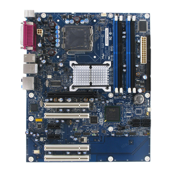
Intel Desktop Board D945PWM Technical Product Specification 1.1.2 Board Layout Figure 1 shows the location of the major components. OM18271 Figure 1. Board Components Table 2 lists the components identified in Figure 1. -
Page 13: Board Components Shown In Figure 1
Auxiliary front panel power LED connector Front panel connector Front panel USB connectors [2] Chassis intrusion connector Intel 82801G I/O Controller Hub (ICH7) SPI flash device IEEE-1394a controller Front panel IEEE-1394a connectors [2] PCI Conventional bus add-in card connectors [2]... -
Page 14: Block Diagram
Intel Desktop Board D945PWM Technical Product Specification 1.1.3 Block Diagram Figure 2 is a block diagram of the major functional areas. PCI Express x1 Interface PCI Express x1 Slot 1 Back Panel/Front Panel USB Ports PCI Express x1 Slot 2... -
Page 15: Online Support
1.3 Processor The board is designed to support Intel Pentium 4 processors in an LGA775 processor socket with a 1066, 800, or 533 MHz system bus. See the Intel web site listed below for the most up-to-date list of supported processors. -
Page 16: System Memory
Intel Desktop Board D945PWM Technical Product Specification 1.4 System Memory The board has four DIMM sockets and support the following memory features: • 1.8 V (only) DDR2 SDRAM DIMMs with gold-plated contacts • Unbuffered, single-sided or double-sided DIMMs with the following restriction: Double-sided DIMMS with x16 organization are not supported. -
Page 17: Memory Configurations
Product Description 1.4.1 Memory Configurations The Intel 82945P MCH supports two types of memory organization: • Dual channel (Interleaved) mode. This mode offers the highest throughput for real world applications. Dual channel mode is enabled when the installed memory capacities of both DIMM channels are equal. -
Page 18: Dual Channel (Interleaved) Mode Configuration With Two Dimms
Intel Desktop Board D945PWM Technical Product Specification 1.4.1.1 Dual Channel (Interleaved) Mode Configurations Figure 4 shows a dual channel configuration using two DIMMs. In this example, the DIMM0 (blue) sockets of both channels are populated with identical DIMMs. Channel A, DIMM 0... -
Page 19: Dual Channel (Interleaved) Mode Configuration With Four Dimms
Product Description Figure 6 shows a dual channel configuration using four DIMMs. In this example, the combined capacity of the two DIMMs in Channel A equal the combined capacity of the two DIMMs in Channel B. Also, the DIMMs are matched between DIMM0 and DIMM1 of both channels. Channel A, DIMM 0 256 MB 512 MB... -
Page 20: Single Channel (Asymmetric) Mode Configuration With One Dimm
Intel Desktop Board D945PWM Technical Product Specification 1.4.1.2 Single Channel (Asymmetric) Mode Configurations NOTE Dual channel (Interleaved) mode configurations provide the highest memory throughput. Figure 7 shows a single channel configuration using one DIMM. In this example, only the DIMM0 (blue) socket of Channel A is populated. -
Page 21: Intel 945P Chipset
® The Intel 945P chipset consists of the following devices: • Intel 82945P Memory Controller Hub (MCH) with Direct Media Interface (DMI) interconnect • Intel 82801G I/O Controller Hub (ICH7) with DMI interconnect The MCH component provides interfaces to the CPU, memory, PCI Express, and the DMI interconnect. -
Page 22: Ide Support
Intel Desktop Board D945PWM Technical Product Specification 1.5.2 IDE Support The board provides five IDE interface connectors: • One parallel ATA IDE connector that supports two devices • Four serial ATA IDE connectors that support one device per connector 1.5.2.1 Parallel ATE IDE Interface The ICH7’s Parallel ATA IDE controller has one bus-mastering Parallel ATA IDE interface. -
Page 23: Real-Time Clock, Cmos Sram, And Battery
Product Description NOTE Many Serial ATA drives use new low-voltage power connectors and require adaptors or power supplies equipped with low-voltage power connectors. For more information, see: http://www.serialata.org/ For information about Refer to The location of the Serial ATA IDE connectors Figure 16, page 50 1.5.3 Real-Time Clock, CMOS SRAM, and Battery A coin-cell battery (CR2032) powers the real-time clock and CMOS memory. - Page 24 Intel Desktop Board D945PWM Technical Product Specification VARO Räjähdysvaara, jos pariston tyyppi on väärä. Paristot on kierrätettävä, jos se on mahdollista. Käytetyt paristot on hävitettävä paikallisten ympäristömääräysten mukaisesti. VORSICHT Bei falschem Einsetzen einer neuen Batterie besteht Explosionsgefahr. Die Batterie darf nur durch denselben oder einen entsprechenden, vom Hersteller empfohlenen Batterietyp ersetzt werden.
- Page 25 Product Description VIGYAZAT Ha a telepet nem a megfelelő típusú telepre cseréli, az felrobbanhat. A telepeket lehetőség szerint újra kell hasznosítani. A használt telepeket a helyi környezetvédelmi előírásoknak megfelelően kell kiselejtezni. AWAS Risiko letupan wujud jika bateri digantikan dengan jenis yang tidak betul. Bateri sepatutnya dikitar semula jika boleh.
- Page 26 Intel Desktop Board D945PWM Technical Product Specification UYARI Yanlış türde pil takıldığında patlama riski vardır. Piller mümkün olduğunda geri dönüştürülmelidir. Kullanılmış piller, yerel çevre yasalarına uygun olarak atılmalıdır. OСТОРОГА Використовуйте батареї правильного типу, інакше існуватиме ризик вибуху. Якщо можливо, використані батареї слід утилізувати. Утилізація використаних батарей...
-
Page 27: Pci Express* Connectors
Product Description 1.6 PCI Express* Connectors The board provides the following PCI Express connectors: • One PCI Express x16 connector supporting simultaneous transfer speeds up to 4 GBytes/sec of peak bandwidth per direction and up to 8 GBytes/sec concurrent bandwidth •... -
Page 28: Legacy I/O Controller
Intel Desktop Board D945PWM Technical Product Specification 1.8 Legacy I/O Controller The legacy I/O controller provides the following features: • One serial port • One parallel port with Extended Capabilities Port (ECP) and Enhanced Parallel Port (EPP) support • Serial IRQ interface compatible with serialized IRQ support for PCI Conventional bus systems •... -
Page 29: Audio Subsystem
Line out and Mic in functions for front panel audio jacks • A signal-to-noise (S/N) ratio of 95 dB 1.9.1 Audio Subsystem Software Audio software and drivers are available from Intel’s World Wide Web site. For information about Refer to Obtaining audio software and drivers Section 1.2, page 15... -
Page 30: Front/Back Panel Audio Connector Options
Intel Desktop Board D945PWM Technical Product Specification Front Panel Audio Connectors Mic In Line Out Surround Left and Right/Retasking Jack [Black] Side Surround Left and Right/ Center channel and LFE (Subwoofer)/ Line In/Retasking Jack Retasking Jack [Orange] [Blue] S/PDIF Digital Audio Out... -
Page 31: Lan Subsystem
PCI Conventional bus power management ⎯ Supports ACPI technology ⎯ Supports LAN wake capabilities 1.10.1 LAN Subsystem Software LAN software and drivers are available from Intel’s World Wide Web site. For information about Refer to Obtaining LAN software and drivers Section 1.2, page 15... -
Page 32: Hardware Management Subsystem
Intel Desktop Board D945PWM Technical Product Specification Table 4 describes the LED states when the board is powered up and the 10/100 Mbits/sec LAN subsystem is operating. Table 4. LAN Connector LED States LED Color LED State Condition Green LAN link is not established. -
Page 33: Fan Monitoring
Product Description 1.11.3 Fan Monitoring Fan monitoring can be implemented using Intel Desktop Utilities or third-party software. The level of monitoring and control is dependent on the hardware monitoring ASIC used on the board. For information about Refer to The functions of the fan connectors Section 1.12.2.2, page 37... -
Page 34: Power Management
Intel Desktop Board D945PWM Technical Product Specification 1.12 Power Management Power management is implemented at several levels, including: • Software support through Advanced Configuration and Power Interface (ACPI) • Hardware support: ⎯ Power connector ⎯ Fan connectors ⎯ LAN wake capabilities ⎯... -
Page 35: Power States And Targeted System Power
Product Description 1.12.1.1 System States and Power States Under ACPI, the operating system directs all system and device power state transitions. The operating system puts devices in and out of low-power states based on user preferences and knowledge of how devices are being used by applications. Devices that are not being used can be turned off. -
Page 36: Hardware Support
Intel Desktop Board D945PWM Technical Product Specification 1.12.1.3 Wake-up Devices and Events Table 7 lists the devices or specific events that can wake the computer from specific states. Table 7. Wake-up Devices and Events These devices/events can wake up the computer…... -
Page 37: Power Connector
Product Description Resume on Ring enables telephony devices to access the computer when it is in a power-managed state. The method used depends on the type of telephony device (external or internal). NOTE The use of Resume on Ring and Wake from USB technologies from an ACPI state requires an operating system that provides full ACPI support. -
Page 38: Lan Wake Capabilities
Intel Desktop Board D945PWM Technical Product Specification 1.12.2.3 LAN Wake Capabilities CAUTION For LAN wake capabilities, the +5 V standby line for the power supply must be capable of providing adequate +5 V standby current. Failure to provide adequate standby current when implementing LAN wake capabilities can damage the power supply. -
Page 39: Location Of The Standby Power Indicator Led
Product Description 1.12.2.7 Wake from PS/2 Devices PS/2 device activity wakes the computer from an ACPI S1 or S3 state. 1.12.2.8 PME# Signal Wake-up Support When the PME# signal on the PCI Conventional bus is asserted, the computer wakes from an ACPI S1, S3, S4, or S5 state (with Wake on PME enabled in BIOS). - Page 40 Intel Desktop Board D945PWM Technical Product Specification...
-
Page 41: Technical Reference
2 Technical Reference What This Chapter Contains Introduction ........................41 Memory Resources ...................... 41 DMA Channels ......................43 Fixed I/O Map....................... 44 PCI Configuration Space Map..................45 Interrupts ........................46 PCI Conventional Interrupt Routing Map ..............47 Connectors........................48 Jumper Block ....................... 59 2.10 Mechanical Considerations .................. -
Page 42: Detailed System Memory Address Map
Intel Desktop Board D945PWM Technical Product Specification • MCH base address registers, internal graphics ranges, PCI Express ports (up to 512 MB) • Memory-mapped I/O that is dynamically allocated for PCI Conventional and PCI Express add-in cards The amount of installed memory that can be used will vary based on add-in cards and BIOS settings. -
Page 43: Memory Map
Technical Reference 2.2.2 Memory Map Table 8 lists the system memory map. Table 8. System Memory Map Address Range (decimal) Address Range (hex) Size Description 1024 K - 4194304 K 100000 - FFFFFFFF 4095 MB Extended memory 960 K - 1024 K F0000 - FFFFF 64 KB Runtime BIOS... -
Page 44: Fixed I/O Map
Address (hex) Size Description 0000 - 00FF 256 bytes Used by the Desktop Board D945PWM. Refer to the ICH7 data sheet for dynamic addressing information. 0170 - 0177 8 bytes Secondary Parallel ATA IDE channel command block 01F0 - 01F7... -
Page 45: Pci Configuration Space Map
PCI Configuration Space Map Device Function Number (hex) Number (hex) Number (hex) Description Memory controller of Intel 82945P component (Note 1) PCI Express x16 graphics port Intel High Definition Audio Controller PCI Express port 1 PCI Express port 2 PCI Express port 3... -
Page 46: Interrupts
Intel Desktop Board D945PWM Technical Product Specification 2.6 Interrupts The interrupts can be routed through either the Programmable Interrupt Controller (PIC) or the Advanced Programmable Interrupt Controller (APIC) portion of the ICH7 component. The PIC is supported in Windows 98 SE and Windows ME and uses the first 16 interrupts. The APIC is supported in Windows 2000 and Windows XP and supports a total of 24 interrupts. -
Page 47: Pci Conventional Interrupt Routing Map
Technical Reference 2.7 PCI Conventional Interrupt Routing Map This section describes interrupt sharing and how the interrupt signals are connected between the PCI Conventional bus connectors and onboard PCI Conventional devices. The PCI Conventional specification describes how interrupts can be shared between devices attached to the PCI Conventional bus. -
Page 48: Connectors
Intel Desktop Board D945PWM Technical Product Specification Table 13. PCI Interrupt Routing Map ICH7 PIRQ Signal Name PCI Interrupt Source PIRQA PIRQB PIRQC PIRQD PIRQE PIRQF PIRQG PIRQH ICH7 LAN INTA PCI bus connector 1 INTD INTA INTB INTC PCI bus connector 2... -
Page 49: Back Panel Connectors
Technical Reference 2.8.1 Back Panel Connectors Figure 15 shows the location of the back panel connectors. The back panel connectors are color-coded. The figure legend (Table 14) lists the colors used (when applicable). OM17828 Figure 15. Back Panel Connectors Table 14 lists the back panel connectors identified in Figure 15. NOTE The back panel audio line out connector is designed to power headphones or amplified speakers only. -
Page 50: Component-Side Connectors
Intel Desktop Board D945PWM Technical Product Specification 2.8.2 Component-side Connectors Figure 16 shows the locations of the component-side connectors. OM18272 Figure 16. Component-side Connectors... -
Page 51: Front Panel Audio Connector
Technical Reference Table 15 lists the component-side connectors identified in Figure 16. Table 15. Component-side Connectors Shown in Figure 16 Item/callout from Figure 16 Description PCI Conventional bus add-in card connector 4 Auxiliary fan connector PCI Conventional bus add-in card connector 3 PCI Express x1 bus add-in card connector 2 PCI Express x1 bus add-in card connector 1 Front panel audio connector... -
Page 52: Serial Ata Connectors
Intel Desktop Board D945PWM Technical Product Specification Table 16. Front Panel Audio Connector Signal Name Signal Name Port E [Port 1] Left Channel Ground Port E [Port 1] Right Channel Presence# (dongle present) Port F [Port 2] Right Channel Port E [Port 1] Sense return... -
Page 53: Processor Fan Connector
Technical Reference Table 19. Processor Fan Connector Signal Name Ground +12 V FAN_TACH FAN_CONTROL 2.8.2.1 Chassis Fan Connectors The board has three chassis fan connectors: • Front chassis fan • Rear chassis fan • Auxiliary fan connector Table 20 lists the signal names for the front and rear chassis fan connectors. Table 22 lists the signal names for the auxiliary fan connector. -
Page 54: Main Power Connector
Main power – a 2 x 12 connector. This connector is compatible with 2 x 10 connectors previously used on Intel Desktop boards. The board supports the use of ATX12V power supplies with either 2 x 10 or 2 x 12 main power cables. When using a power supply with a 2 x 10 main power cable, attach that cable on the rightmost pins of the main power connector, leaving pins 11, 12, 23, and 24 unconnected. -
Page 55: Auxiliary Front Panel Power/Sleep Led Connector
⎯ The SMBus clock line is connected to pin A40. ⎯ The SMBus data line is connected to pin A41. NOTE The PCI Express x16 connector is configured to support only a PCI Express x1 link when the Intel GMA950 graphics controller is enabled. ® 2.8.2.4 Auxiliary Front Panel Power/Sleep LED Connector Pins 1 and 3 of this connector duplicate the signals on pins 2 and 4 of the front panel connector. -
Page 56: Connection Diagram For Front Panel Connector
Intel Desktop Board D945PWM Technical Product Specification 2.8.2.5 Front Panel Connector This section describes the functions of the front panel connector. Table 25 lists the signal names of the front panel connector. Figure 17 is a connection diagram for the front panel connector. -
Page 57: States For A One-Color Power Led
Technical Reference 2.8.2.5.2 Reset Switch Connector [Purple] Pins 5 and 7 [Purple] can be connected to a momentary single pole, single throw (SPST) type switch that is normally open. When the switch is closed, the board resets and runs the POST. 2.8.2.5.3 Power/Sleep LED Connector [Green] Pins 2 and 4 [Green] can be connected to a one- or two-color LED. -
Page 58: Connection Diagram For Front Panel Usb Connectors
Intel Desktop Board D945PWM Technical Product Specification 2.8.2.6 Front Panel USB Connectors Figure 18 is a connection diagram for the front panel USB connectors. INTEGRATOR’S NOTES • The +5 V DC power on the USB connector is fused. • Pins 1, 3, 5, and 7 comprise one USB port. -
Page 59: Jumper Block
Technical Reference 2.9 Jumper Block CAUTION Do not move the jumper with the power on. Always turn off the power and unplug the power cord from the computer before changing a jumper setting. Otherwise, the board could be damaged. Figure 20 shows the location of the jumper block. The jumper block determines the BIOS Setup program’s mode. -
Page 60: Mechanical Considerations
Intel Desktop Board D945PWM Technical Product Specification 2.10 Mechanical Considerations 2.10.1 Form Factor The board is designed to fit into an ATX-form-factor chassis. Figure 21 illustrates the mechanical form factor of the board. Dimensions are given in inches [millimeters]. The outer dimensions are 12.00 inches by 9.60 inches [304.80 millimeters by 243.84 millimeters]. -
Page 61: I/O Shield
Additional design considerations for I/O shields relative to chassis requirements are described in the ATX specification. NOTE The I/O shield drawings in this document are for reference only. I/O shields compliant with the ATX chassis specification 2.03 are available from Intel. 162.3 REF [6.390] 1.6 ± 0.12 [0.063 ±... -
Page 62: Electrical Considerations
The boards are designed to provide 2 A (average) of +5 V current for each add-in board. The total +5 V current draw for both boards is as follows: a fully loaded D945PWM board (all six expansion slots and the PCI Express x16 slot filled) must not exceed 14 A. -
Page 63: Fan Connector Current Capability
Technical Reference 2.11.3 Fan Connector Current Capability CAUTION The processor fan must be connected to the processor fan connector, not to a chassis fan connector. Connecting the processor fan to a chassis fan connector may result in onboard component damage that will halt fan operation. Table 30 lists the current capability of the fan connectors. -
Page 64: Thermal Considerations
All responsibility for determining the adequacy of any thermal or system design remains solely with the reader. Intel makes no warranties or representations that merely following the instructions presented in this document will result in a system with adequate thermal performance. -
Page 65: Localized High Temperature Zones
(item A in Figure 24) can reach a temperature of up to 85 C in an open chassis. Figure 24 shows the locations of the localized high temperature zones. OM17961 Item Description Processor voltage regulator area Processor Intel 82945P MCH Intel 82801G ICH7 Figure 24. Localized High Temperature Zones... -
Page 66: Reliability
The calculation is based on the Bellcore Reliability Prediction Procedure, TR-NWT-000332, Issue 4, September 1991. The MTBF prediction is used to estimate repair rates and spare parts requirements. The MTBF data is calculated from predicted data at 55 ºC. The MTBF for the D945PWM board is 108,165 hours. -
Page 67: Environmental
Technical Reference 2.14 Environmental Table 32 lists the environmental specifications for the board. Table 32. Environmental Specifications Parameter Specification Temperature -40 °C to +70 °C Non-Operating 0 °C to +55 °C Operating Shock Unpackaged 50 g trapezoidal waveform Velocity change of 170 inches/second² Packaged Half sine 2 millisecond Product weight (pounds) -
Page 68: Regulatory Compliance
Product Ecology statements • Electromagnetic Compatibility (EMC) regulations • Product certification markings 2.15.1 Safety Regulations Desktop Board D945PWM complies with the safety regulations stated in Table 33 when correctly installed in a compatible host system. Table 33. Safety Regulations Regulation Title UL 60950-1:2003/ Information Technology Equipment –... - Page 69 Technical Reference Čeština Tento výrobek odpovídá požadavkům evropských směrnic 89/336/EEC a 73/23/EEC. Dansk Dette produkt er i overensstemmelse med det europæiske direktiv 89/336/EEC & 73/23/EEC. Dutch Dit product is in navolging van de bepalingen van Europees Directief 89/336/EEC & 73/23/EEC. Eesti Antud toode vastab Euroopa direktiivides 89/336/EEC ja 73/23/EEC kehtestatud nõuetele.
-
Page 70: Product Ecology Statements
Como parte de su compromiso de responsabilidad medioambiental, Intel ha implantado el programa de reciclaje de productos Intel, que permite que los consumidores al detalle de los productos Intel devuelvan los productos usados en los lugares seleccionados para su correspondiente reciclado. - Page 71 Technical Reference Français Dans le cadre de son engagement pour la protection de l'environnement, Intel a mis en œuvre le programme Intel Product Recycling Program (Programme de recyclage des produits Intel) pour permettre aux consommateurs de produits Intel de recycler les produits usés en les retournant à des adresses spécifiées.
-
Page 72: Lead Free Desktop Board
Intel Desktop Board D945PWM Technical Product Specification Türkçe Intel, çevre sorumluluğuna bağımlılığının bir parçası olarak, perakende tüketicilerin Intel markalı kullanılmış ürünlerini belirlenmiş merkezlere iade edip uygun şekilde geri dönüştürmesini amaçlayan Intel Ürünleri Geri Dönüşüm Programı’nı uygulamaya koymuştur. Bu programın ürün kapsamı, ürün iade merkezleri, nakliye talimatları, kayıtlar ve şartlar v.s dahil bütün ayrıntılarını... -
Page 73: Emc Regulations
Technical Reference 2.15.4 EMC Regulations Desktop Board D945PWM complies with the EMC regulations stated in Table 35 when correctly installed in a compatible host system. Table 35. EMC Regulations Regulation Title FCC Class B Title 47 of the Code of Federal Regulations, Parts 2 and 15, Subpart B, Radio Frequency Devices. -
Page 74: Product Certification Markings (Board Level)
Intel Desktop Board D945PWM Technical Product Specification 2.15.5 Product Certification Markings (Board Level) Desktop Board D945PWM has the product certification markings shown in Table 36: Table 36. Product Certification Markings Description Mark UL joint US/Canada Recognized Component mark. Includes adjacent UL file number for Intel desktop boards: E210882. -
Page 75: Overview Of Bios Features
BIOS Security Features ....................81 3.1 Introduction The boards use an Intel BIOS that is stored in the Serial Peripheral Interface Flash Memory (SPI Flash) and can be updated using a disk-based program. The SPI Flash contains the BIOS Setup program, POST, the PCI auto-configuration utility, and Plug and Play support. -
Page 76: Bios Flash Memory Organization
Intel Desktop Board D945PWM Technical Product Specification Table 37 lists the BIOS Setup program menu features. Table 37. BIOS Setup Program Menu Bar Maintenance Main Advanced Security Power Boot Exit Clears Displays Configures Sets Configures Selects boot Saves or passwords and... -
Page 77: System Management Bios (Smbios)
Overview of BIOS Features performance. To take advantage of the high capacities typically available today, hard drives are automatically configured for Logical Block Addressing (LBA) and to PIO Mode 3 or 4, depending on the capability of the drive. You can override the auto-configuration options by specifying manual configuration in the BIOS Setup program. -
Page 78: Bios Updates
To install an operating system that supports USB, follow the operating system’s installation instructions. 3.6 BIOS Updates The BIOS can be updated using either of the following utilities, which are available on the Intel World Wide Web site: • Intel Express BIOS Update utility, which enables automated updating while in the Windows ®... -
Page 79: Boot Options
Overview of BIOS Features 3.7 Boot Options In the BIOS Setup program, the user can choose to boot from a diskette drive, hard drives, CD-ROM, or the network. The default setting is for the diskette drive to be the first boot device, the hard drive second, and the ATAPI CD-ROM third. -
Page 80: Adjusting Boot Speed
It is possible to optimize the boot process to the point where the system boots so quickly that the Intel logo screen (or a custom logo splash screen) will not be seen. Monitors and hard disk drives with minimum initialization times can also contribute to a boot time that might be so fast that necessary logo screens and POST messages cannot be seen. -
Page 81: Bios Security Features
Overview of BIOS Features 3.9 BIOS Security Features The BIOS includes security features that restrict access to the BIOS Setup program and who can boot the computer. A supervisor password and a user password can be set for the BIOS Setup program and for booting the computer, with the following restrictions: •... - Page 82 Intel Desktop Board D945PWM Technical Product Specification...
-
Page 83: Error Messages And Beep Codes
4 Error Messages and Beep Codes What This Chapter Contains Speaker ........................83 BIOS Beep Codes......................83 BIOS Error Messages ....................83 Port 80h POST Codes ....................84 4.1 Speaker The board-mounted speaker provides audible error code (beep code) information during POST. For information about Refer to The location of the onboard speaker... -
Page 84: Port 80H Post Codes
Intel Desktop Board D945PWM Technical Product Specification 4.4 Port 80h POST Codes During the POST, the BIOS generates diagnostic progress codes (POST-codes) to I/O port 80h. If the POST fails, execution stops and the last POST code generated is left at port 80h. This code is useful for determining the point where an error occurred. -
Page 85: Port 80H Post Codes
Error Messages and Beep Codes Table 44. Port 80h POST Codes POST Code Description of POST Operation Host Processor Power-on initialization of the host processor (Boot Strap Processor) Host processor Cache initialization (including APs) Starting Application processor initialization SMM initialization Chipset Initializing a chipset component Memory... - Page 86 Intel Desktop Board D945PWM Technical Product Specification Table 44. Port 80h POST Codes (continued) POST Code Description of POST Operation Keyboard (PS2 or USB) Resetting keyboard Disabling keyboard Detecting presence of keyboard Enabling keyboard Clearing keyboard input buffer Instructing keyboard controller to run Self Test (PS2 only)
- Page 87 Error Messages and Beep Codes Table 44. Port 80h POST Codes (continued) POST Code Description of POST Operation DXE Drivers Waiting for user input Checking password Entering BIOS setup TBD – Flash Update Calling Legacy Option ROMs TBD – Calling INT 19. One beep unless silent boot is enabled. TBD –...
-
Page 88: Typical Port 80H Post Sequence
Intel Desktop Board D945PWM Technical Product Specification Table 45. Typical Port 80h POST Sequence POST Code Description Initializing a chipset component Reading SPD from memory DIMMs Detecting presence of memory DIMMs Configuring memory Testing memory Loading recovery capsule Entered DXE phase...
Need help?
Do you have a question about the D945PWM and is the answer not in the manual?
Questions and answers