Table of Contents
Advertisement
Advertisement
Table of Contents

Related Manuals for Asus P8Q67-M DO


Summary of Contents for Asus P8Q67-M DO
- Page 1 P8Q67-M DO/TPM P8Q67-M DO/USB3/TPM...
- Page 2 Product warranty or service will not be extended if: (1) the product is repaired, modified or altered, unless such repair, modification of alteration is authorized in writing by ASUS; or (2) the serial number of the product is defaced or missing.
-
Page 3: Table Of Contents
Contents Notices ......................vi Safety information ..................vii About this guide ..................viii P8Q67-M DO Series specifications summary .......... ix Chapter 1: Product introduction Before you proceed ..............1-1 Motherboard overview ..............1-2 1.2.1 Motherboard layout ............1-2 1.2.2 Layout contents ............... 1-3 Central Processing Unit (CPU) ........... - Page 4 Contents Main menu .................. 2-10 2.3.1 System Language [English] ...........2-11 2.3.2 System Date [Day xx/xx/xxxx] ........2-11 2.3.3 System Time [xx:xx:xx] ..........2-11 2.3.4 Security ................2-11 Ai Tweaker menu ................ 2-12 2.4.1 Memory Frequency [Auto] ..........2-13 2.4.2 iGPU Max. Frequency [Auto] ........2-13 2.4.3 EPU Power Saving Mode [Disabled] ......
- Page 5 Setup Mode [EZ Mode] ..........2-28 2.7.5 Boot Option Priorities ............ 2-28 2.7.6 Boot Override ..............2-28 Tools menu ................. 2-29 2.8.1 ASUS EZ Flash Utility ........... 2-29 2.8.2 ASUS SPD Information ..........2-29 2.8.3 ASUS O.C. Profile ............2-29 Exit menu ..................2-30...
-
Page 6: Notices
This class B digital apparatus complies with Canadian ICES-003. ASUS Recycling/Takeback Services ASUS recycling and takeback programs come from our commitment to the highest standards for protecting our environment. We believe in providing solutions for you to be able to responsibly recycle our products, batteries, other components as well as the packaging materials. -
Page 7: Safety Information
Complying with the REACH (Registration, Evaluation, Authorisation, and Restriction of Chemicals) regulatory framework, we published the chemical substances in our products at ASUS REACH website at http://csr.asus.com/english/REACH.htm. DO NOT throw the motherboard in municipal waste. This product has been designed to enable proper reuse of parts and recycling. -
Page 8: About This Guide
Refer to the following sources for additional information and for product and software updates. ASUS websites The ASUS website provides updated information on ASUS hardware and software products. Refer to the ASUS contact information. Optional documentation Your product package may include optional documentation, such as warranty flyers, that may have been added by your dealer. -
Page 9: P8Q67-M Do Series Specifications Summary
Dual-channel memory architecture The maximum 32GB memory capacity can be supported with 8GB or above DIMMs. ASUS will update the memory QVL once the DIMMs are available in the market. ** Refer to www.asus.com for the latest Memory QVL (Qualified Vendors List). - Page 10 1 x DVI-D port 1 x VGA port 1 x LAN (RJ-45) port 6 x USB 2.0/1.1 ports (P8Q67-M DO/TPM only) 4 x USB 2.0/1.1 ports; 2 x USB 3.0 ports (P8Q67-M DO/ USB3/TPM only) 3 x Audio jacks Internal connectors / 4 x USB 2.0/1.1 connectors support additional 8 USB 2.0/1.1...
-
Page 11: Chapter 1: Product Introduction
Refer to page x for the list of accessories. If any of the items is damaged or missing, contact your retailer. ASUS P8Q67-M DO Series motherboards include P8Q67-M DO/TPM and P8Q67-M DO/USB3/TPM two models. The layout varies with models. The layout illustrations in this user guide are for P8Q67-M DO/USB3/TPM only. -
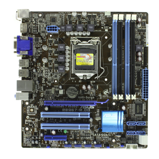
Page 12: Motherboard Overview
DIS_ME F_PANEL CHASSIS • 2 x USB 3.0 ports (blue) on P8Q67-M DO/USB3/TPM, OR: • 2 x USB 2.0/1.1 ports (black) on P8Q67-M DO/TPM Place six screws into the holes indicated by circles to secure the motherboard to the chassis. DO NOT overtighten the screws! Doing so can damage the motherboard. -
Page 13: Layout Contents
Contact your retailer immediately if the PnP cap is missing, or if you see any damage to the PnP cap/socket contacts/motherboard components. ASUS will shoulder the cost of repair only if the damage is shipment/transit-related. • Keep the cap after installing the motherboard. ASUS will process Return Merchandise Authorization (RMA) requests only if the motherboard comes with the cap on the LGA1155 socket. -
Page 14: System Memory
• The maximum 32GB memory capacity can be supported with 8GB or above DIMMs. ASUS will update the memory QVL once the DIMMs are available in the market. • Due to the memory address limitation on 32-bit Windows OS, when you install 4GB ®... - Page 15 2.4 Ai Tweaker menu for manual memory frequency adjustment. • For system stability, use a more efficient memory cooling system to support a full memory load (4 DIMMs) or overclocking condition. P8Q67-M DO Series Motherboard Qualified Vendors Lists (QVL) DDR3-1333 MHz capability DIMM socket Chip...
- Page 16 • • POWER SILICON SP002GBLTU133S02 elixir N2CB1680AN-C6 • • • POWER TAKEMS TMS1GB364D081-107EY 7-7-7-20 1.5V • • TAKEMS TMS2GB364D082-138EW 8-8-8-24 1.5V • • UMAX E41302GP0-73BDB UMAX U2S24D30TP-13 • • WINTEC 3WVS31333-2G-CNR AMPO AM3420803-13H • • • ASUS P8Q67-M DO Series...
- Page 17 • C*: Supports two pairs of modules inserted into both the blue slots and the black slots as two pairs of dual-channel memory configuration. Visit the ASUS website at www.asus.com for the latest QVL. Chapter 1: Product introduction...
-
Page 18: Expansion Slots
This motherboard supports PCI Express x4 network cards, SCSI cards, and other cards that comply with the PCI Express specifications. 1.5.5 PCI Express x16 slot This motherboard has a PCI Express 2.0 x16 slot that supports PCI Express x16 2.0 graphic cards complying with the PCI Express specifications. ASUS P8Q67-M DO Series... -
Page 19: Jumpers
Normal Clear RTC (Default) P8Q67-M DO/USB3/TPM Clear RTC RAM To erase the RTC RAM: 1. Turn OFF the computer and unplug the power cord. 2. Move the jumper cap from pins 1-2 (default) to pins 2-3. Keep the cap on pins 2-3 for about 5-10 seconds, then move the cap back to pins 1-2. -
Page 20: Connectors
LAN port LED indications Speed Activity Link ACT/LINK LED SPEED LED Status Description Status Description No link 10 Mbps connection ORANGE Linked ORANGE 100 Mbps connection BLINKING Data activity GREEN 1 Gbps connection LAN port 1-10 ASUS P8Q67-M DO Series... - Page 21 • We strongly recommend that you connect USB 3.0 devices to USB 3.0 ports for faster and better performance for your USB 3.0 devices. USB 2.0 ports 3 and 4 ( black, on P8Q67-M DO/TPM) . These two 4-pin Universal Serial Bus (USB) ports are available for connecting USB 2.0/1.1 devices.
-
Page 22: Internal Connectors
Legacy AC’97 pin definition compliant definition P8Q67-M DO/USB3/TPM Front panel audio connector • We recommend that you connect a high-definition front panel audio module to this connector to avail of the motherboard’s high-definition audio capability. • If you want to connect a high-definition front panel audio module to this connector, set the Front Panel Type item in the BIOS setup to [HD]. - Page 23 By default, the pin labeled “Chassis Signal” and “Ground” are shorted with a jumper cap. Remove the jumper caps only when you intend to use the chassis intrusion detection feature. CHASSIS P8Q67-M DO/USB3/TPM P8Q67-M DO/USB3/TPM Chassis intrusion connector Chapter 1: Product introduction 1-13...
- Page 24 • If you are uncertain about the minimum power supply requirement for your system, refer to the Recommended Power Supply Wattage Calculator at http://support.asus. com/PowerSupplyCalculator/PSCalculator.aspx?SLanguage=en-us for details. Digital audio connector (4-1 pin SPDIF_OUT) This connector is for an additional Sony/Philips Digital Interface (S/PDIF) port.
- Page 25 Gb/s signal cables. SATA6G_1 SATA6G_2 P8Q67-M DO/USB3/TPM P8Q67-M DO/USB3/TPM Intel SATA 6.0Gb/s connectors ® • These connectors are set to [IDE Mode] by default. In IDE mode, you can connect Serial ATA boot/data hard disk drives to these connectors. If you intend to create a Serial ATA RAID set using these connectors, set the SATA Mode item in the BIOS to [RAID Mode].
- Page 26 The Serial ATA RAID feature (RAID 0, 1, 5, and 10) is available only if you are using Windows XP SP3 or later version. ® • When using hot-plug and NCQ, set the SATA Mode item in the BIOS to [AHCI Mode]. See section 2.5.5 SATA Configuration for details. 1-16 ASUS P8Q67-M DO Series...
-
Page 27: System Panel Connector
PIN 1 P8Q67-M DO/USB3/TPM +HDLED RESET P8Q67-M DO/USB3/TPM System panel connector • System power LED (2-pin PLED) This 2-pin connector is for the system power LED. Connect the chassis power LED cable to this connector. The system power LED lights up when you turn on the system power, and blinks when the system is in sleep mode. - Page 28 PIN 1 PIN 1 PIN 1 P8Q67-M DO/USB3/TPM P8Q67-M DO/USB3/TPM USB2.0 connectors Never connect a 1394 cable to the USB connectors. Doing so will damage the motherboard! The USB module cable is purchased separately. Speaker connector (4-pin SPEAKER) The 4-pin connector is for the chassis-mounted system warning speaker. The speaker allows you to hear system beeps and warnings.
-
Page 29: Software Support
The contents of the Support DVD are subject to change at any time without notice. Visit the ASUS website at www.asus.com for updates. To run the Support DVD Place the Support DVD to the optical drive. -
Page 30: Chapter 2: Bios Information
BIOS in the future. Copy the original motherboard BIOS using the ASUS Update utility. 2.1.1 ASUS Update utility The ASUS Update is a utility that allows you to manage, save, and update the motherboard BIOS in Windows environment. ®... -
Page 31: Asus Ez Flash 2
Follow the onscreen instructions to complete the updating process. 2.1.2 ASUS EZ Flash 2 The ASUS EZ Flash 2 feature allows you to update the BIOS without using an OS-based utility. Before you start using this utility, download the latest BIOS file from the ASUS website at www.asus.com. -
Page 32: Asus Crashfree Bios 3 Utility
2.1.3 ASUS CrashFree BIOS 3 utility The ASUS CrashFree BIOS 3 is an auto recovery tool that allows you to restore the BIOS file when it fails or gets corrupted during the updating process. You can restore a corrupted BIOS file using the motherboard support DVD or a USB flash drive that contains the updated BIOS file. -
Page 33: Asus Bios Updater
2.1.4 ASUS BIOS Updater The ASUS BIOS Updater allows you to update BIOS in DOS environment. This utility also allows you to copy the current BIOS file that you can use as a backup when the BIOS fails or gets corrupted during the updating process. - Page 34 The BIOS Updater backup screen appears indicating the BIOS backup process. When BIOS backup is done, press any key to return to the DOS prompt. ASUSTek BIOS Updater for DOS V1.18 Current ROM Update ROM BOARD: P8Q67-M DO/TPM BOARD: Unknown VER: 0302 VER:...
-
Page 35: Updating The Bios File
Select the Load Optimized Defaults item under the Exit menu. Refer to section 2.9 Exit menu for details. • Ensure to connect all SATA hard disk drives after updating the BIOS file if you have disconnected them. ASUS P8Q67-M DO Series... -
Page 36: Bios Setup Program
• The BIOS setup screens shown in this section are for reference purposes only, and may not exactly match what you see on your screen. • Visit the ASUS website at www.asus.com to download the latest BIOS file for this motherboard. -
Page 37: Bios Menu Screen
Selects the boot device priority • The boot device options vary depending on the devices you installed to the system. • The Boot Menu(F8) button is available only when the boot device is installed to the system. ASUS P8Q67-M DO Series... -
Page 38: Advanced Mode
The Advanced Mode provides advanced options for experienced end-users to configure the BIOS settings. The figure below shows an example of the Advanced Mode. Refer to the following sections for the detailed configurations. To access the EZ Mode, click Exit, then select ASUS EZ Mode. Back button Menu items... -
Page 39: Main Menu
CPU Information Intel(R) Core(TM) i5-2400 CPU @ 3.10GHz Speed 3100 MHz Memory Information Total Memory 1024 MB Speed 1333 MHz System Language English System Date [Mon 12/27/2010] System Time [16:46:15] Access Level Administrator > Security ASUS P8Q67-M DO Series 2-10... -
Page 40: System Language [English]
2.3.1 System Language [English] Allows you to choose the BIOS language version from the options. Configuration options: [English] 2.3.2 System Date [Day xx/xx/xxxx] Allows you to set the system date. 2.3.3 System Time [xx:xx:xx] Allows you to set the system time. 2.3.4 Security The Security menu items allow you to change the system security settings. -
Page 41: Ai Tweaker Menu
F1: General Help DRAM Voltage 1.500V Auto F2: Previous Values F5: Optimized Defaults VCCIO Voltage 1.050V Auto F10: Save ESC: Exit PCH Voltage 1.050V Auto Load-Line Calibration Auto Version 2.00.1201. Copyright (C) 2010 American Megatrends, Inc. ASUS P8Q67-M DO Series 2-12... -
Page 42: Memory Frequency [Auto]
Target DRAM Speed : xxxxMHz Displays the current DRAM speed. 2.4.1 Memory Frequency [Auto] Allows you to set the memory operating frequency. Configuration options: [DDR3-800MHz] [DDR3-1066MHz] [DDR3-1333MHz] Selecting a very high memory frequency may cause the system to become unstable! If this happens, revert to the default setting. -
Page 43: Offset Mode Sign [+]
Allows you to set the CPU voltage. The values range from -0.635V to +0.635V with a 0.005V interval. Refer to the CPU documentation before setting the CPU voltage. Setting a high voltage may damage the CPU permanently, and setting a low voltage may make the system unstable. ASUS P8Q67-M DO Series 2-14... -
Page 44: Igpu Offset Mode Sign [+]
2.4.8 iGPU Offset Mode Sign [+] To offset the voltage by a positive value. [–] To offset the voltage by a negative value. iGPU Voltage [Auto] Allows you to set the iGPU voltage. The values range from -0.635V to +0.635V with a 0.005V interval. -
Page 45: Advanced Menu
Allows you to enable or disable the TPM support. Configuration options: [Disabled] [Enabled] 2.5.2 CPU Configuration The items in this menu show the CPU-related information that the BIOS automatically detects. The items shown in submenu may be different due to the CPU you installed. ASUS P8Q67-M DO Series 2-16... - Page 46 CPU Ratio [Auto] Allows you to set the ratio between the CPU Core Clock and the BCLK Frequency. Use <+> and <-> keys or the numeric keypad to adjust the ratio. The valid value ranges vary according to your CPU model. Intel Adaptive Thermal Monitor [Enabled] [Enabled] Enables the overheated CPU to throttle its clock speed to cool down.
-
Page 47: System Agent Configuration
[RAID Mode] Set to [RAID Mode] when you want to create a RAID configuration from the SATA hard disk drives. ASUS P8Q67-M DO Series 2-18... -
Page 48: Intel Txt(Lt) Configuration
Serial-ATA Controller 0 [Enhanced] This item appears only when you set the SATA Mode item to [IDE Mode]. [Disabled] Disables the SATA function. [Enhanced] Set to [Enhanced] to support more than four SATA devices. [Compatible] Set to [Compatible] when using Windows 98/NT/2000/MS-DOS. Up to four SATA devices are supported under these operating systems. -
Page 49: Usb Configuration
USB controller legacy mode is enabled. If no USB device is detected, the legacy USB support is disabled. Legacy USB3.0 Support [Enabled] This item appears only on P8Q67-M DO/USB3/TPM. [Enabled] Enables the support for USB 3.0 devices on legacy operating systems (OS). -
Page 50: Onboard Devices Configuration
[Enabled] Enables the onboard USB 3.0 controller. [Disabled] Disables the controller. Asmedia USB 3.0 Battery Charging Support [Disabled] (P8Q67-M DO/USB3/ TPM only) This item appears only when the ASMedia USB 3.0 Controller item is set to [Enabled]. [Enabled] Enables ASMedia USB 3.0 fast battery charging support for USB 3.0 devices complying with the BC 1.1 regulation. -
Page 51: Apm
The system goes into on state after an AC power loss. [Power Off] The system goes into off state after an AC power loss. [Last State] The system goes into either off or on state, whatever the system state was before the AC power loss. ASUS P8Q67-M DO Series 2-22... -
Page 52: Serial Port Console Redirection
Power On By PS/2 Keyboard [Disabled] [Disabled] Disables the Power On by a PS/2 keyboard. [Space Bar] Sets the Space Bar on the PS/2 keyboard to turn on the system. [Ctrl-Esc] Sets the Ctrl+Esc key on the PS/2 keyboard to turn on the system. [Power Key] Sets Power key on the PS/2 keyboard to turn on the system. -
Page 53: Monitor Menu
5V Voltage +5.080 V Version 2.00.1201. Copyright (C) 2010 American Megatrends, Inc. Scroll down to display the following items: 12V Voltage +12.192 V Anti Surge Support Enabled Version 2.00.1201. Copyright (C) 2010 American Megatrends, Inc. ASUS P8Q67-M DO Series 2-24... -
Page 54: Cpu Temperature / Mb Temperature [Xxxºc/Xxxºf]
2.6.1 CPU Temperature / MB Temperature [xxxºC/xxxºF] The onboard hardware monitor automatically detects and displays the CPU and motherboard temperatures. Select Ignore if you do not wish to display the detected temperatures. 2.6.2 CPU / Chassis Fan Speed [xxxx RPM] or [Ignore] / [N/A] The onboard hardware monitor automatically detects and displays the CPU and chassis fan speeds in rotations per minute (RPM). -
Page 55: Chassis Q-Fan Control [Enabled]
The onboard hardware monitor automatically detects the voltage output through the onboard voltage regulators. Select Ignore if you do not want to detect this item. 2.6.6 Anti Surge Support [Enabled] This item allows you to enable or disable the Anti Surge function. Configuration options: [Disabled] [Enabled] ASUS P8Q67-M DO Series 2-26... -
Page 56: Boot Menu
[Disabled] Disables the full screen logo display feature. Set this item to [Enabled] to use the ASUS MyLogo 2™ feature. Post Report [5 sec] This item appears only when the Full Screen Logo item is set to [Disabled] and allows you to set the waiting time for the system to display the post report. -
Page 57: Setup Mode [Ez Mode]
• To select the boot device during system startup, press <F8> when ASUS Logo appears. • To access Windows OS in Safe Mode, press <F8> after POST. -
Page 58: Tools Menu
> ASUS O.C. Profile 2.8.1 ASUS EZ Flash Utility Allows you to run ASUS EZ Flash 2. Press [Enter] to launch the ASUS EZ Flash 2 screen. For more details, see section 2.1.2 ASUS EZ Flash 2. 2.8.2 ASUS SPD Information... -
Page 59: Exit Menu
This option allows you to enter the EZ Mode screen. Launch EFI Shell from filesystem device This option allows you to attempt to launch the EFI Shell application (shellx64.efi) from one of the available devices that have a filesystem. ASUS P8Q67-M DO Series 2-30... -
Page 60: Asus Contact Information
+1-510-739-3777 +1-510-608-4555 Web site usa.asus.com Technical Support Telephone +1-812-282-2787 Support fax +1-812-284-0883 Online support support.asus.com ASUS COMPUTER GmbH (Germany and Austria) Address Harkort Str. 21-23, D-40880 Ratingen, Germany +49-2102-959911 Web site www.asus.de Online contact www.asus.de/sales Technical Support Telephone (Component) +49-1805-010923*...
Need help?
Do you have a question about the P8Q67-M DO and is the answer not in the manual?
Questions and answers