Table of Contents
Advertisement
Advertisement
Table of Contents

Related Manuals for Asus P8H61-M PLUS2


Summary of Contents for Asus P8H61-M PLUS2
- Page 1 P8H61-M PLUS 2...
- Page 2 Product warranty or service will not be extended if: (1) the product is repaired, modified or altered, unless such repair, modification of alteration is authorized in writing by ASUS; or (2) the serial number of the product is defaced or missing.
-
Page 3: Table Of Contents
Contents Notices ......................vi Safety information ..................vii About this guide ..................viii P8H61-M PLUS2 specifications summary ..........ix Chapter 1: Product introduction Before you proceed ..............1-1 Motherboard overview ..............1-2 1.2.1 Placement direction ............1-2 1.2.2 Screw holes ..............1-2 1.2.3... - Page 4 Managing and updating your BIOS ..........2-1 2.1.1 ASUS Update utility ............2-1 2.1.2 ASUS EZ Flash 2 ............2-2 2.1.3 ASUS CrashFree BIOS 3 utility ........2-3 2.1.4 ASUS BIOS Updater ............2-4 BIOS setup program ..............2-7 Main menu .................. 2-11 2.3.1 System Language ............2-11...
- Page 5 Setup Mode ..............2-23 2.7.6 Boot Option Priorities ............ 2-23 2.7.7 Boot Override ..............2-23 Tools menu ................. 2-24 2.8.1 ASUS EZ Flash 2 Utility ..........2-24 2.8.2 ASUS SPD Information ..........2-24 2.8.3 ASUS O.C. Profile ............2-24 Exit menu ..................2-25...
-
Page 6: Notices
This class B digital apparatus complies with Canadian ICES-003. ASUS Recycling/Takeback Services ASUS recycling and takeback programs come from our commitment to the highest standards for protecting our environment. We believe in providing solutions for you to be able to responsibly recycle our products, batteries, other components as well as the packaging materials. -
Page 7: Safety Information
Complying with the REACH (Registration, Evaluation, Authorisation, and Restriction of Chemicals) regulatory framework, we published the chemical substances in our products at ASUS REACH website at http://csr.asus.com/english/REACH.htm. DO NOT throw the motherboard in municipal waste. This product has been designed to enable proper reuse of parts and recycling. -
Page 8: About This Guide
Refer to the following sources for additional information and for product and software updates. ASUS websites The ASUS website provides updated information on ASUS hardware and software products. Refer to the ASUS contact information. Optional documentation Your product package may include optional documentation, such as warranty flyers, that may have been added by your dealer. -
Page 9: P8H61-M Plus2 Specifications Summary
Extreme Memory Profile (XMP) ® * The maximum 16GB memory capacity can be supported with 8GB or above DIMMs. ASUS will update the memory QVL once the DIMMs are available in the market. ** Refer to www.asus.com for the latest Memory QVL (Qualified Vendors List). - Page 10 P8H61-M PLUS2 specifications summary Rear panel ports 1 x PS/2 keyboard / mouse combo port 1 x DVI-D port 1 x D-Sub port 1 x LAN (RJ-45) port 6 x USB 2.0/1.1 ports 3 x Audio jacks Internal connectors/ 2 x USB 2.0/1.1 connectors support additional 4 USB 2.0/1.1...
-
Page 11: Chapter 1: Product Introduction
Chapter 1 Product introduction Thank you for buying an ASUS P8H61-M PLUS2 motherboard! ® Before you start installing the motherboard, and hardware devices on it, check the items in your motherboard package. Refer to page x for the list of accessories. -
Page 12: Motherboard Overview
Place six screws into the holes indicated by circles to secure the motherboard to the chassis. Do not overtighten the screws! Doing so can damage the motherboard. Place this side towards the rear of the chassis P8H61-M PLUS2 ASUS P8H61-M PLUS2... -
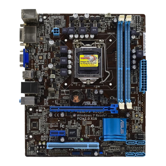
Page 13: Motherboard Layout
1.2.3 Motherboard layout 20.3cm(8.0in) KB_USB56 CPU_FAN ATX12V USB34 CHA_FAN LAN1_USB12 Lithium Cell 8111E CMOS Power AUDIO PCIEX16 P8H61-M PLUS2 Super Intel ® PCIEX1_1 32Mb BIOS SB_PWR PCI1 SATA3G_2 SATA3G_1 USB78 USB910 F_PANEL SATA3G_4 SATA3G_3 SPEAKER AAFP 1.2.4 Layout contents Connectors/Jumpers/Slots/LED... -
Page 14: Central Processing Unit (Cpu)
Contact your retailer immediately if the PnP cap is missing, or if you see any damage to the PnP cap/socket contacts/motherboard components. ASUS will shoulder the cost of repair only if the damage is shipment/transit-related. • Keep the cap after installing the motherboard. ASUS will process Return Merchandise Authorization (RMA) requests only if the motherboard comes with the cap on the LGA1155 socket. - Page 15 Lift the load lever in the direction of the arrow until the load plate is completely lifted. Load plate Remove the PnP cap from the CPU socket by lifting the tab only. PnP cap Position the CPU over the socket, ensuring that the gold triangle is on the bottom-left corner of the socket, and CPU notches...
- Page 16 Close the load plate (A), and then push down the load lever (B), ensuring that the front edge of the load plate slides under the retention knob (C). Insert the load lever under the retention tab. ASUS P8H61-M PLUS2...
-
Page 17: Installing The Cpu Heatsink And Fan
1.3.2 Installing the CPU heatsink and fan The Intel LGA1155 processor requires a specially designed heatsink and fan assembly to ® ensure optimum thermal condition and performance. • When you buy a boxed Intel processor, the package includes the CPU fan and ®... -
Page 18: Uninstalling The Cpu Heatsink And Fan
Connect the CPU fan cable to the connector on the motherboard labeled CPU_FAN. CPU_FAN P8H61-M PLUS2 P8H61-M PLUS2 CPU fan connector Do not forget to connect the CPU fan connector! Hardware monitoring errors can occur if you fail to plug this connector. -
Page 19: System Memory
DDR2 DIMM socket. DDR3 modules are developed for better performance with less power consumption. The figure illustrates the location of the DDR3 DIMM sockets: Channel Sockets Channel A DIMM_A1 Channel B DIMM_B1 P8H61-M PLUS2 P8H61-M PLUS2 240-pin DDR3 DIMM sockets Chapter 1: Product introduction... -
Page 20: Memory Configurations
• The maximum 16GB memory capacity can be supported with 8GB or above DIMMs. ASUS will update the memory QVL once the DIMMs are available in the market. • The default memory operation frequency is dependent on its Serial Presence Detect (SPD), which is the standard way of accessing information from a memory module. - Page 21 DDR3-1333 MHz capability DIMM socket support Chip Vendors Part No. Size Chip NO. Timing Voltage (Optional) Brand 1 DIMM 2 DIMMs A-Data AD31333001GOU SS A-Data AD30908C8D-151C E0906 - • • A-Data AD31333G001GOU 3GB(3 x 1GB) SS - 8-8-8-24 1.65-1.85V • •...
-
Page 22: Channel Memory Configuration
• A*: Supports one module inserted into either slot as single-channel memory configuration. • B*: Supports one pair of modules inserted into both the blue slots as one pair of dual- channel memory configuration. Visit the ASUS website at www.asus.com for the latest QVL. 1-12 ASUS P8H61-M PLUS2... -
Page 23: Installing A Dimm
1.4.3 Installing a DIMM Unplug the power supply before adding or removing DIMMs or other system components. Failure to do so can cause severe damage to both the motherboard and the components. Press the retaining clips outward to DIMM notch unlock a DIMM socket. -
Page 24: Expansion Slots
This motherboard supports PCI Express x1 network cards, SCSI cards, and other cards that comply with the PCI Express specifications. 1.5.5 PCI Express x16 slot This motherboard has a PCI Express 2.0 x16 slot that supports PCI Express x16 2.0 graphic cards complying with the PCI Express specifications. 1-14 ASUS P8H61-M PLUS2... -
Page 25: Jumpers
Normal Clear RTC (Default) P8H61-M PLUS2 Clear RTC RAM To erase the RTC RAM: 1. Turn OFF the computer and unplug the power cord. 2. Move the jumper cap from pins 1-2 (default) to pins 2-3. Keep the cap on pins 2-3 for about 5-10 seconds, then move the cap back to pins 1-2. -
Page 26: Connectors
Mic In Mic In Bass/Center Bass/Center Lime (Front panel) – – – Side Speaker Out To configure an 8-channel audio output: Use a chassis with HD audio module in the front panel to support 8-channel audio output. 1-16 ASUS P8H61-M PLUS2... -
Page 27: Internal Connectors
Legacy AC’97 pin definition compliant definition P8H61-M PLUS2 Front panel audio connector • We recommend that you connect a high-definition front panel audio module to this connector to avail of the motherboard’s high-definition audio capability. • If you want to connect a high-definition front panel audio module to this connector, set the Front Panel Type item in the BIOS setup to [HD]. - Page 28 The system may become unstable or may not boot up if the power is inadequate. • If you are uncertain about the minimum power supply requirement for your system, refer to the Recommended Power Supply Wattage Calculator at http://support.asus. com/PowerSupplyCalculator/PSCalculator.aspx?SLanguage=en-us for details. Intel H61 Serial ATA 3.0Gb/s connectors (7-pin SATA3G_1~4)
-
Page 29: Cpu/Chassis Fan Connectors 4-Pin Cpu_Fan/4-Pin Cha_Fan
CPU_FAN CHA_FAN P8H61-M PLUS2 P8H61-M PLUS2 Fan connectors Do not forget to connect the fan cables to the fan connectors. Insufficient air flow inside the system may damage the motherboard components. These are not jumpers! Do not place jumper caps on the fan connectors! The CPU_FAN connector supports a CPU fan of maximum 2A (24 W) fan power. - Page 30 PIN 1 P8H61-M PLUS2 +HDLED RESET P8H61-M PLUS2 System panel connector • System power LED (2-pin PLED) This 2-pin connector is for the system power LED. Connect the chassis power LED cable to this connector. The system power LED lights up when you turn on the system power, and blinks when the system is in sleep mode.
-
Page 31: Software Support
The contents of the Support DVD are subject to change at any time without notice. Visit the ASUS website at www.asus.com for updates. To run the Support DVD Place the Support DVD into the optical drive. - Page 32 1-22 ASUS P8H61-M PLUS2...
-
Page 33: Chapter 2: Bios Information
BIOS in the future. Copy the original motherboard BIOS using the ASUS Update utility. 2.1.1 ASUS Update utility The ASUS Update is a utility that allows you to manage, save, and update the motherboard BIOS in Windows environment. ®... -
Page 34: Asus Ez Flash 2
Follow the onscreen instructions to complete the updating process. 2.1.2 ASUS EZ Flash 2 The ASUS EZ Flash 2 feature allows you to update the BIOS without using an OS-based utility. Before you start using this utility, download the latest BIOS file from the ASUS website at www.asus.com. -
Page 35: Asus Crashfree Bios 3 Utility
2.1.3 ASUS CrashFree BIOS 3 utility The ASUS CrashFree BIOS 3 is an auto recovery tool that allows you to restore the BIOS file when it fails or gets corrupted during the updating process. You can restore a corrupted BIOS file using the motherboard support DVD or a USB flash drive that contains the updated BIOS file. -
Page 36: Asus Bios Updater
2.1.4 ASUS BIOS Updater The ASUS BIOS Updater allows you to update BIOS in DOS environment. This utility also allows you to copy the current BIOS file that you can use as a backup when the BIOS fails or gets corrupted during the updating process. - Page 37 The BIOS Updater backup screen appears indicating the BIOS backup process. When BIOS backup is done, press any key to return to the DOS prompt. ASUSTek BIOS Updater for DOS V1.18 Current ROM Update ROM BOARD: P8H61-M PLUS2 BOARD: Unknown VER: 0302 VER:...
-
Page 38: Updating The Bios File
Select the Load Optimized Defaults item under the Exit menu. Refer to section 2.9 Exit menu for details. • Ensure to connect all SATA hard disk drives after updating the BIOS file if you have disconnected them. ASUS P8H61-M PLUS2... -
Page 39: Bios Setup Program
• The BIOS setup screens shown in this section are for reference purposes only, and may not exactly match what you see on your screen. • Visit the ASUS website at www.asus.com to download the latest BIOS file for this motherboard. -
Page 40: Bios Menu Screen
Selects the boot device priority • The boot device options vary depending on the devices you installed to the system. • The Boot Menu(F8) button is available only when the boot device is installed to the system. ASUS P8H61-M PLUS2... -
Page 41: Advanced Mode
The Advanced Mode provides advanced options for experienced end-users to configure the BIOS settings. The figure below shows an example of the Advanced Mode. Refer to the following sections for the detailed configurations. To access the EZ Mode, click Exit, then select ASUS EZ Mode. Back button Menu items... -
Page 42: Menu Items
You cannot select an item that is not user-configurable. A configurable field is highlighted when selected. To change the value of a field, select it and press <Enter> to display a list of options. 2-10 ASUS P8H61-M PLUS2... -
Page 43: Main Menu
Main menu The Main menu screen appears when you enter the Advanced Mode of the BIOS Setup program. The Main menu provides you an overview of the basic system information, and allows you to set the system date, time, language, and security settings. EFI BIOS Utility - Advanced Mode Exit Main... -
Page 44: Administrator Password
To clear the user password, follow the same steps as in changing a user password, but press <Enter> when prompted to create/confirm the password. After you clear the password, the User Password item on top of the screen shows Not Installed. 2-12 ASUS P8H61-M PLUS2... -
Page 45: Ai Tweaker Menu
Ai Tweaker menu The Ai Tweaker menu items allow you to configure overclocking-related items. Be cautious when changing the settings of the Ai Tweaker menu items. Incorrect field values can cause the system to malfunction. The configuration options for this section vary depending on the CPU and DIMM model you installed on the motherboard. -
Page 46: Igpu Max. Frequency
<-> keys to adjust the value. To restore the default setting, type [auto] using the keyboard and press <Enter>. Changing the values in this menu may cause the system to become unstable! If this happens, revert to the default settings. 2-14 ASUS P8H61-M PLUS2... -
Page 47: Advanced Menu
Advanced menu The Advanced menu items allow you to change the settings for the CPU and other system devices. Be cautious when changing the settings of the Advanced menu items. Incorrect field values can cause the system to malfunction. EFI BIOS Utility - Advanced Mode Exit Ai Tweaker Main... - Page 48 Allows you to disable or enable the CPU C3 report to the operating system. Configuration options: [Disabled] [Enabled] CPU C6 Report [Enabled] Allows you to disable or enable the CPU C6 report to the operating system. Configuration options: [Enabled] [Disabled] 2-16 ASUS P8H61-M PLUS2...
-
Page 49: System Agent Configuration
2.5.2 System Agent Configuration Initiate Graphic Adapter [PEG/iGPU] Allows you to decide which graphics controller to use as the primary boot device. Configuration options: [iGPU] [PCI/iGPU] [PCI/PEG] [PEG/iGPU] [PEG/PCI] iGPU Memory [64M] Allows you to set the iGPU memory size. Configuration options: [32M] [64M] [96M] [128M] Render Standby [Enabled] Allows you to enable or disable Render Standby by internal graphics devices. -
Page 50: Usb Configuration
[HD] Sets the front panel audio connector (AAFP) mode to high definition audio. [AC97] Sets the front panel audio connector (AAFP) mode to legacy AC’97 2-18 ASUS P8H61-M PLUS2... -
Page 51: Apm
Realtek LAN Controller [Enabled] [Enabled] Enables the Realtek LAN controller. [Disabled] Disables the controller. Realtek PXE OPROM [Disabled] This item appears only when you set the previous item to [Enabled] and allows you to enable or disable the PXE OptionRom of the Realtek LAN controller. Configuration options: [Enabled] [Disabled] 2.5.7 Restore AC Power Loss [Power Off]... -
Page 52: Monitor Menu
This item appears only when you enable the CPU Q-Fan Control feature and allows you to disable or set the CPU fan warning speed. Configuration options: [Ignore] [200 RPM] [300 RPM] [400 RPM] [500 RPM] [600 RPM] 2-20 ASUS P8H61-M PLUS2... -
Page 53: Chassis Q-Fan Control
CPU Fan Profile [Standard] This item appears only when you enable the CPU Q-Fan Control feature and allows you to set the appropriate performance level of the CPU fan. [Standard] Sets to [Standard] to make the CPU fan automatically adjust depending on the CPU temperature. -
Page 54: Boot Menu
[Disabled] Disables the full screen logo display feature. Set this item to [Enabled] to use the ASUS MyLogo 2™ feature. Post Report [5 sec] This item appears only when the Full Screen Logo item is set to [Disabled] and allows you to set the waiting time for the system to display the post report. -
Page 55: Option Rom Messages
• To select the boot device during system startup, press <F8> when ASUS Logo appears. • To access Windows OS in Safe Mode, press <F8> after POST. -
Page 56: Tools Menu
> ASUS O.C. Profile 2.8.1 ASUS EZ Flash 2 Utility Allows you to run ASUS EZ Flash 2. Press [Enter] to launch the ASUS EZ Flash 2 screen. For more details, see section 2.1.2 ASUS EZ Flash 2. 2.8.2 ASUS SPD Information... -
Page 57: Exit Menu
Load Optimized Defaults Save Changes & Reset Discard Changes & Exit ASUS EZ Mode Launch EFI Shell from filesystem device Load Optimized Defaults This option allows you to load the default values for each of the parameters on the Setup menus. - Page 58 2-26 ASUS P8H61-M PLUS2...
-
Page 59: Asus Contact Information
+1-510-739-3777 +1-510-608-4555 Web site usa.asus.com Technical Support Telephone +1-812-282-2787 Support fax +1-812-284-0883 Online support support.asus.com ASUS COMPUTER GmbH (Germany and Austria) Address Harkort Str. 21-23, D-40880 Ratingen, Germany +49-2102-959911 Web site www.asus.de Online contact www.asus.de/sales Technical Support Telephone (Component) +49-1805-010923*...
Need help?
Do you have a question about the P8H61-M PLUS2 and is the answer not in the manual?
Questions and answers